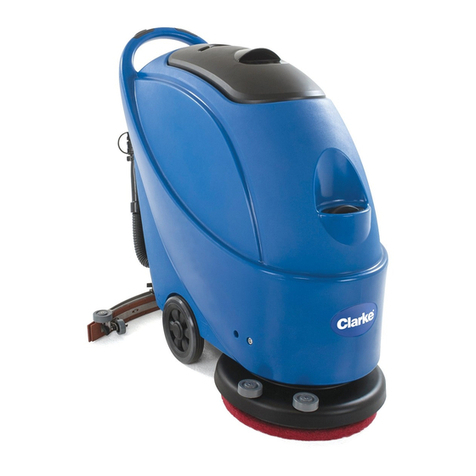
Tennant 550 User manual

550
*MM149*
www.tennantco.com
MM149
Rev. 28 (10-2010)
TennantTruetParts and Supplies
Rider Scrubber
Manual
(Electric)

This manual is furnished with each new model. It provides
necessary operation and maintenance instructions.
Read this manual completely and understand the ma-
chine before operating or servicing it.
This machine will provide excellent service. However, the
best results will be obtained at minimum costs if:
SThe machine is operated with reasonable care.
SThe machine is maintained regularly - per the ma-
chine maintenance instructions provided.
SThe machine is maintained with manufacturer sup-
plied or equivalent parts.
PROTECT THE ENVIRONMENT
Please dispose of packaging materials,
old machine components such as
batteries, hazardous fluids such as
antifreeze and oil, in a safe
environmentally way according to your
local waste disposal regulations.
Always remember to recycle.
MACHINE DATA
Please fill out at time of installation for future reference.
Model No.- 550E
Serial No.-
Machine Options --
Sales Rep. --
Sales Rep. phone no. --
Customer Number --
Installation Date --
Tennant Company
PO Box 1452
Minneapolis, MN 55440
Phone: (800) 553--8033 or (763) 523--2850
www.tennantco.com
SRS is a United States registered trademark of the Tennant Company.
Specifications and parts are subject to change without notice.
Copyright E1986--1989, 1991--2002, 2005, 2006, 2010 TENNANT, Printed in U.S.A.

GENERAL INFORMATION
i
550E MM149 (8--02)
SAFETY PRECAUTIONS
The following symbols are used throughout this
manual as indicated in their descriptions:
WARNING: To warn of hazards or
unsafe practices which could result in
severe personal injury or death.
FOR SAFETY: To identify actions which
must be followed for safe operation of
equipment.
The following information signals potentially
dangerous conditions to the operator or
equipment. Read this manual carefully. Know
when these conditions can exist. Locate all safety
devices on the machine. Then, take necessary
steps to train machine operating personnel.
Report machine damage or faulty operation
immediately. Do not use the machine if it is not in
proper operating condition.
WARNING: Batteries Emit Hydrogen
Gas. Explosion Or Fire Can Result.
Keep Sparks And Open Flame Away.
Keep Covers Open When Charging.
WARNING: Flammable Materials Can
Cause An Explosion Or Fire. Do Not Use
Flammable Materials In Solution Tank.
WARNING: Flammable materials or
reactive metals can cause explosion or
fire. Do not pick up.
WARNING: Moving Belt. Keep Away.
WARNING: Falling Scrub Head. Block
Scrub Head Up Before Working Under It.
WARNING: Crush Hazard Between Front
And Rear Halves Of Machine. Put
Locking Pin In Pivot Lock Before Going
Between Machine Halves.
WARNING: Hazardous Voltage. Shock
Or Electrocution Can Result.
Disconnect Batteries Before Working
On Machine. Only Qualified Personnel
Should Work Inside Panel.
WARNING: Strong Vacuum. Keep Away
From Fan Inlet When Fan Is Running.
FOR SAFETY:
1. Do Not Operate Machine:
-- Unless Trained And Authorized.
-- Unless Operation Manual Is Read And
Understood.
-- In Flammable Or Explosive Areas
Unless Modified For Use In Those
Areas.
-- In Areas With Possible Falling Objects
Unless Equipped With Overhead
Guard.
2. Before Starting Machine:
-- Make Sure All Safety Devices Are In
Place And Operate Properly.
-- Check Brakes And Steering For Proper
Operation.
3. When Starting Machine:
-- Keep Foot On Brake And Directional
Pedal In Neutral.
4. When Using Machine:
-- Use Brakes To Stop Machine.
-- Go Slow On Grades And Slippery
Surfaces.
-- Use Care When Reversing Machine.
-- Do Not Carry Riders On Machine.
-- Always Follow Safety And Traffic
Rules.
-- Report Machine Damage or Faulty
Operation Immediately.
-- Follow mixing and handling
instructions on chemical containers.
5. Before Leaving Or Servicing Machine:
-- Stop On Level Surface.
-- Set Parking Brake.
-- Turn Off Machine And Remove Key.

GENERAL INFORMATION
550E MM149 (8--02)
ii
6. When Servicing Machine:
-- AvoidMovingParts.DoNotWear
Loose Jackets, Shirts, Or Sleeves.
-- Block Machine Tires Before Jacking
Machine Up.
-- Jack Machine Up At Designated
Locations Only. Block Machine Up
With Jack Stands.
-- Use A Hoist Or Jack That Will Support
The Weight Of The Machine
-- Disconnect Battery Connections
Before Working On Machine.
-- Wear Eye And Ear Protection When
Using Pressurized Air Or Water.
-- Avoid Contact With Battery Acid.
-- Use Cardboard To Locate Leaking
Hydraulic Fluid Under Pressure.
-- Use TENNANT Supplied Or Approved
Replacement Parts.
7. When loading/unloading machine
onto/off truck or trailer:
-- Turn off machine.
-- Use truck or trailer that will support
the weight of the machine.
-- Use winch. Do not drive the machine
onto/off the truck or trailer unless the
load height is 380 mm (15 in) or less
from the ground.
-- Set parking brake after machine is
loaded.
-- Block machine tires.
-- Tie machine down to truck or trailer.
The following safety decals are mounted on the
machine in the locations indicated. If these, or any
decal becomes damaged or illegible, install a new
decal in its place.
04336
TRAVEL SPEED CAUTION LABEL --
LOCATED ON THE SIDE OPERATOR
PANEL
03785
BATTERY CHARGING CAUTION LABEL
-- LOCATED ON REAR OF BATTERY
COMPARTMENT.

GENERAL INFORMATION
iii
550E MM149 (8--02)
03788
PINCH SPACE DANGER LABEL --
LOCATED ON THE SOLUTION TANK
04336
03787
SCRUB HEAD LOCK WARNING LABEL
-- LOCATED ON THE SCRUB HEAD
HIGH VOLTAGE WARNING LABEL --
LOCATED ON CONTROL PANEL AND
UNDER THE INSTRUMENT PANEL
04335
FAN SUCTION DANGER LABEL --
LOCATED ON THE SOLUTION TANK
AND VACUUM FAN HOUSING
03786

GENERAL INFORMATION
550E MM149 (12--05)
iv
CONTENTS
Page
GENERAL INFORMATION i..................
SAFETY PRECAUTIONS i................
SPECIFICATIONS 1-1.....................
MACHINE SPECIFICATIONS 1-3.........
POWER TYPE 1-3...................
POWER TRAIN 1-3..................
STEERING 1-3......................
HYDRAULIC SYSTEM 1-3............
BRAKING SYSTEM 1-4..............
SUSPENSION SYSTEM 1-4..........
SYSTEM FLUID CAPACITIES 1-4.....
GENERAL MACHINE
DIMENSIONS/CAPACITIES 1-4....
MACHINE WEIGHTS 1-4.............
GENERAL MACHINE
PERFORMANCE 1-4..............
UL BATTERY REQUIREMENTS 1-5......
UL BATTERY REQUIREMENT FOR
THE TYPE “E” MACHINE 1-5.......
BATTERY ENCLOSURE 1-5.......
BATTERY 1-5....................
MACHINE DIMENSIONS 1-6.............
OPERATION 2-1............................
PREPARATION FOR OPERATION 2-3......
AFTER UNLOADING AND BEFORE
OPERATING THE MACHINE: 2-3.....
OPERATION OF CONTROLS 2-4..........
MACHINE COMPONENTS 2-4..........
INSTRUMENTS AND CONTROLS 2-5...
BRAKE PEDAL 2-6....................
DIRECTIONAL PEDAL 2-6..............
PARKING BRAKE LEVERS 2-6..........
SCRUB HEAD LOCK LEVER 2-6........
PIVOT LOCK PIN 2-7..................
OPERATOR SEAT 2-7..................
HAZARD LIGHT SWITCH (OPTION) 2-7..
ROTATING LIGHT SWITCH
(OPTION) 2-7......................
OPERATING LIGHTS SWITCH
(OPTION) 2-7......................
MASTER POWER SWITCH 2-7.........
MOTOR START PUSH BUTTON 2-7.....
CLIMB PUSH BUTTON 2-7.............
Page
LEVEL PUSH BUTTON 2-7.............
DRAIN TANK LAMP (OPTION) 2-8.......
SQUEEGEE POSITION LAMP 2-8.......
HOUR METER 2-8.....................
SCRUB BRUSH PRESSURE GAUGE 2-8
BATTERY CONDITION GAUGE 2-8......
PANEL LAMP (OPTION) 2-8............
SCRUB BRUSH SWITCH 2-8...........
SQUEEGEE SWITCH 2-8...............
SCRUB HEAD POSITION CONTROL
LEVER 2-8.........................
SOLUTION CONTROL LEVER 2-9.......
STEERING WHEEL 2-9................
SRS LIQUID LOW LEVEL LAMPS
(OPTION) 2-9......................
SRS CLEANING SOLUTION FLOW
CONTROL KNOB (OPTION) 2-9......
FUSES AND CIRCUIT BREAKERS 2-9...
MACHINE OPERATION 2-10...............
NORMAL SCRUBBING OPERATION 2-10
PRE-START CHECKLIST 2-10........
TO START MACHINE 2-10...........
TO FILL SOLUTION TANK 2-10.......
TO SCRUB 2-11....................
TO DRAIN AND CLEAN RECOVERY
TANK AND EMPTY
HOPPER 2-12................
POST OPERATION CHECKLIST --
MOTOR OPERATING 2-13.....
TO STOP MACHINE 2-13............
POST OPERATION CHECKLIST --
MOTOR STOPPED 2-13.......
DOUBLE SCRUBBING OPERATION 2-13
OPERATION ON GRADES 2-13.........
MACHINE TROUBLESHOOTING 2-14...
OPTION OPERATION 2-15................
VACUUM WAND 2-15..................
TO OPERATE VACUUM WAND: 2-15.
TOWING AND TRANSPORTING THE
MACHINE 2-16........................
TOWING THE MACHINE 2-16...........
TRANSPORTING THE MACHINE 2-16...
MACHINE JACKING LOCATIONS 2-18...
MACHINE STORAGE 2-19.................
STORING MACHINE 2-19..............

GENERAL INFORMATION
v
550E MM149 (12--05)
Page
MAINTENANCE 3-1.......................
RECOMMENDED FIRST 50-HOUR
MACHINE INSPECTION 3-3............
MAINTENANCE CHART 3-4...............
LUBRICATION 3-6........................
VACUUM FAN SHAFT 3-6..............
MACHINE PIVOT 3-6..................
SCRUB HEAD PIVOT 3-7...............
SCRUB HEAD HINGES 3-7.............
REAR SQUEEGEE CASTERS 3-7.......
SCRUB BRUSH IDLER PLUGS 3-8......
REAR WHEELS 3-8....................
SCRUB BRUSH DRIVE CHAINS 3-8.....
POWER WHEEL 3-8...................
HYDRAULICS 3-9........................
HYDRAULIC FLUID 3-9................
HYDRAULIC FLUID RESERVOIR 3-9....
HYDRAULIC FLUID FILTER 3-10........
TO REPLACE HYDRAULIC FLUID
FILTER ELEMENT 3-10...........
HYDRAULIC FLUID LEAKS 3-10........
ELECTRICAL SYSTEM 3-11...............
BATTERIES 3-11......................
BATTERY REPLACEMENT 3-12.........
BATTERY CHARGING 3-12.............
TO CHARGE BATTERIES 3-13..........
ELECTRIC MOTORS 3-13..............
CONTROL PANEL 3-13.................
DIRECTIONAL PEDAL 3-14.............
BELTS AND CHAINS 3-15.................
VACUUM FAN DRIVE BELT 3-15........
PUMP DRIVE BELT 3-15...............
STATIC DRAG CHAIN 3-15.............
SCRUB BRUSH DRIVE CHAINS 3-15....
SCRUB HEAD 3-16.......................
SCRUB HEAD 3-16....................
TO ADJUST SCRUB HEAD
HEIGHT 3-16....................
TO ADJUST SCRUB
BRUSH PATTERN 3-17...........
SCRUB BRUSHES 3-19................
TO REPLACE SCRUB BRUSHES 3-19
Page
SOLUTION SYSTEM 3-20.................
RECOVERY TANK 3-20................
WATER SPRAY DEFLECTOR 3-20......
SRS WATER SPRAY DEFLECTOR 3-21..
SRS SOLUTION TANK 3-22.............
SOLUTION DISPENSING TUBE 3-23....
SRS CLEANING SOLUTION
FILTER 3-23........................
SRS METERING SOLUTION PUMP 3-23.
TROUBLESHOOTING 3-23.............
SQUEEGEES 3-24
........................
SIDE SQUEEGEES 3-24...............
REAR SQUEEGEE 3-24................
TO REPLACE REAR
SQUEEGEE BLADES 3-25...........
TO FACTORY ADJUST
REAR SQUEEGEE 3-25.............
TO ADJUST REAR SQUEEGEE 3-28....
BRAKES AND TIRES 3-30.................
SERVICE BRAKES 3-30................
PARKING BRAKES 3-30................
TIRES 3-31...........................
POWER WHEEL 3-31..................
APPENDIX 4-1............................
HARDWARE INFORMATION 4-3.........
STANDARD BOLT TORQUE CHART 4-3
METRIC BOLT TORQUE CHART 4-3..
BOLT IDENTIFICATION 4-3...........
THREAD SEALANT AND LOCKING
COMPOUNDS 4-3................
HYDRAULIC FITTING INFORMATION 4-4.
HYDRAULIC TAPERED PIPE FITTING
(NPT) TORQUE CHART 4-4........
HYDRAULIC TAPERED SEAT FITTING
(JIC) TORQUE CHART 4-4.........
HYDRAULIC O--RING FITTING
TORQUE CHART 4-4..............

GENERAL INFORMATION
550E MM149 (12--05)
vi
Page
HOW TO USE THIS MANUAL 5-1...........
IMPORTANT INFORMATION 5-1........
FINDING A TENNANT PART NUMBER 5-2
PLACING AN ORDER 5-3..............
Fig. 1 -- Recommended General Maintenance
Items 6-2...................
Fig. 2 -- Replacement Brushes 6-4........
Fig. 3 -- Main Frame Group 6-6...........
Fig. 4 -- Seat Group 6-8..................
Fig. 5 -- Main Frame Noise Insulation
Group 6-9..................
Fig. 6 -- Speed And Directional Pedal
Group 6-10..................
Fig. 7 -- Scrub Head Hopper Group 6-11....
Fig. 8 -- Scrub Head Right SideSqueegee
Assembly 6-12...............
Fig. 9 -- Scrub Head Left Side Squeegee
Assembly 6-13...............
Fig. 10 -- Scrub Head Lift Group 6-14.......
Fig. 11 -- Scrub Head Solution Supply
and Control Group 6-16.......
Fig. 12 -- Scrub Head Front Brush Drive
Components Group 6-18......
Fig. 13 -- Scrub Head Front Brush Idler
Assembly 6-20...............
Fig. 14 -- Scrub Head Rear Brush Idler
Assembly 6-21...............
Fig. 15 -- Scrub Head Rear Brush Drive
Components Group 6-22......
Fig. 16 -- Vacuum Fan Assembly 6-24......
Fig. 17 -- Electric Motor Group 6-26.........
Fig. 18 -- Steering Column Group 6-28......
Fig. 19 -- Instrument Panel Group 6-30......
Fig. 20 -- Instrument Panel Components
Group 6-31..................
Fig. 21 -- Control Panel Components
Group 6-32..................
Fig. 22 -- MFR Control Assembly 6-34......
Fig. 23 -- Electrical Schematic 6-35.........
Fig. 24 -- Power Wheel Group 6-38.........
Fig. 25 -- Electrical Wire Harness Group 6-40
Fig. 26 -- Front Wheel Assembly 6-42.......
Fig. 27 -- Front Wheel Brakes Group 6-43...
Fig. 28 -- Front Wheel Parking Brake
Group 6-44..................
Fig. 29 -- Hydraulic Pump Group 6-45.......
Fig. 30 -- Hydraulic Control Valve
Group 6-46..................
Fig. 31 -- Hydraulic Schematic
(001330--005607) 6-47........
Fig. 32 -- Hydraulic Schematic
(005608-- ) 6-48.........
Fig. 33 -- Hydraulic Filter Group 6-49.......
Fig. 34 -- Hydraulic Hoses Group
(001330--005607) 6-50........
Fig. 35 -- Hydraulic Hoses Group
(005608-- ) 6-52........
Fig. 36 -- Trunnion Group 6-54.............
Page
Fig. 37 -- Solution and Recovery Tanks
Group, Front Side 6-56........
Fig. 38 -- Solution and Recovery Tanks
Group, Rear Side 6-58........
Fig. 39 -- Rear Wheel Group 6-60..........
Fig. 40 -- Rear Wheel Parking Brake
Handle Group 6-61...........
Fig. 41 -- Rear Wheel Parking Brake
Group 6-62..................
Fig. 42 -- Rear Bumper Group 6-63.........
Fig. 43 -- Rear Squeegee Assembly 6-64....
SRS PARTS 7-1..
Fig. 1 -- SRS Solution Supply and Control
Group 7-2
Fig. 2 -- SRS Control Panel Assembly 7-5..
Fig. 3 -- SRS Front Side of Solution Tank
Group, (001330--004933) 7-6....
Fig. 4 -- SRS Front Side of Solution Tank
Group, (004934-- ) 7-8.....
Fig. 5 -- SRS Rear Side of Solution Tank
Group, (001330--004933) 7-10.
Fig. 6 -- SRS Rear Side of Solution Tank
Group, (004934-- ) 7-12..
Fig. 7 -- SRS Wire Harnesses 7-14.........
OPTIONS 8-1.............................
Fig. 1 -- Overhead Guard Kit 8-2..........
Fig. 2 -- Revolving Light Kit 8-3...........
Fig. 3 -- Heavy Duty Bumper Kit 8-4.......
Fig. 4 -- SRS Heavy Duty Bumper Kit 8-5...
Fig. 5 -- SRS Sludge Removal Tool 8-6.....
Fig. 6 -- Solution Tank Drain Kit 8-7........
Fig. 7 -- Fire Extinguisher Kit 8-7..........
Fig. 8 -- Operating Light Kit 8-8...........
Fig. 9 -- SRS Operating Light Kit
(001330--004933) 8-8........
Fig. 10 -- SRS Operating Light Kit
(004934-- ) 8-9............
Fig. 11 -- Squeegee Wand Kit 8-10.........
Fig. 12 -- SRS Squeegee Wand Kit 8-12.....
Fig. 13 -- Mirror Kit 8-14...................
Fig. 14 -- Tire and Wheel Kit, Foam Filled 8-14
Fig. 15 -- Dust Shield Kit 8-15..............
Fig. 16 -- Battery Chargers 8-15............
Fig. 17 -- Batteries 8-15...................
Fig. 18 -- Batteries (International) 8-15......
Fig. 19 -- Side Squeegee Extension Kit 8-16.
Fig. 20 -- Documentation Group 8-17.......
BREAKDOWNS 9-1..........................
Fig. 1 -- SRS Metering Solution Pump
Breakdown, 16485 9-2.......
Fig. 2 -- SRS Solution Pump Breakdown,
79326--1 9-3..................
Fig. 3 -- Power Wheel Breakdown, 75274 9-4
Fig. 4 -- Pump Breakdown, 76043 9-5......
Fig. 5 -- Hydraulic Steering Valve
Breakdown, 57982 9-6.......

GENERAL INFORMATION
vii
550E MM149 (12--05)
Page
Fig. 6 -- Hydraulic Steering Valve
Breakdown, 74176 9-7.......
Fig. 7 -- Hydraulic Steering Valve
Breakdown, 65242 9-8.......
Fig. 8 -- Solenoid Control Valve
Breakdown, 31574 9-9.......
Fig. 9 -- Steering Cylinder Breakdown,
04431 9-10..................
Fig. 10 -- Control Valve Breakdown,
48108A 9-11.................
Fig. 11 -- Front Brush Drive Motor
Breakdown, 76213 9-12.......
Fig. 12 -- Rear Brush Drive Motor
Breakdown, 76214 9-12.......
Fig. 13 -- Electric Motor Breakdown,
16450 9-12..................
Fig. 14 -- Electric Motor Breakdown,
03462 9-12..................
Fig. 15 -- Propelling Motor Breakdown,
76017 9-13..................
Fig. 16 -- Electric Relay Breakdown,
76095 9-13..................
Fig. 17 -- Electric Relay Breakdown,
76096 9-13..................
Fig. 18 -- Electric Relay Breakdown,
76092 9-14..................
CROSS REFERENCE 10-1..................
PART NUMBER TO PAGE NUMBER CROSS
REFERENCE LIST 10-2...........
PART DESCRIPTION TO PAGE NUMBER
CROSS REFERENCE LIST 10-8....

GENERAL INFORMATION
550E MM149 (3--94)
viii

OPERATION
2-1
550E MM149 (12--05)
SECTION 2
CONTENTS
Page
PREPARATION FOR OPERATION 2-3.........
AFTER UNLOADING AND BEFORE
OPERATING THE MACHINE: 2-3........
OPERATION OF CONTROLS 2-4.............
MACHINE COMPONENTS 2-4.............
INSTRUMENTS AND CONTROLS 2-5......
BRAKE PEDAL 2-6.......................
DIRECTIONAL PEDAL 2-6.................
PARKING BRAKE LEVERS 2-6.............
SCRUB HEAD LOCK LEVER 2-6...........
PIVOT LOCK PIN 2-7.....................
OPERATOR SEAT 2-7....................
HAZARD LIGHT SWITCH (OPTION) 2-7....
ROTATING LIGHT SWITCH (OPTION) 2-7..
OPERATING LIGHTS SWITCH (OPTION) 2-7
MASTER POWER SWITCH 2-7............
MOTOR START PUSH BUTTON 2-7........
CLIMB PUSH BUTTON 2-7................
LEVEL PUSH BUTTON 2-7................
DRAIN TANK LAMP (OPTION) 2-8..........
SQUEEGEE POSITION LAMP 2-8..........
HOUR METER 2-8........................
SCRUB BRUSH PRESSURE GAUGE 2-8...
BATTERY CONDITION GAUGE 2-8........
PANEL LAMP (OPTION) 2-8...............
SCRUB BRUSH SWITCH 2-8..............
SQUEEGEE SWITCH 2-8.................
SCRUB HEAD POSITION CONTROL
LEVER 2-8............................
SOLUTION CONTROL LEVER 2-9.........
STEERING WHEEL 2-9...................
SRS LIQUID LOW LEVEL
LAMPS (OPTION) 2-9..................
SRS CLEANING SOLUTION FLOW
CONTROL KNOB (OPTION) 2-9.........
FUSES AND CIRCUIT BREAKERS 2-9......
Page
MACHINE OPERATION 2-10..................
NORMAL SCRUBBING OPERATION 2-10...
PRE-START CHECKLIST 2-10..........
TO START MACHINE 2-10..............
TO FILL SOLUTION TANK 2-10.........
TO SCRUB 2-11.......................
TO DRAIN AND CLEAN RECOVERY
TANK AND EMPTY HOPPER 2-12....
POST OPERATION CHECKLIST --
MOTOR OPERATING 2-13...........
TO STOP MACHINE 2-13...............
POST OPERATION CHECKLIST --
MOTOR STOPPED 2-13.............
DOUBLE SCRUBBING OPERATION 2-13...
OPERATION ON GRADES 2-13............
MACHINE TROUBLESHOOTING 2-14......
OPTION OPERATION 2-15...................
VACUUM WAND 2-15
.....................
TO OPERATE VACUUM WAND: 2-15....
TOWING AND TRANSPORTING THE
MACHINE 2-16...........................
TOWING THE MACHINE 2-16..............
TRANSPORTING THE MACHINE 2-16......
MACHINE JACKING LOCATIONS 2-18......
MACHINE STORAGE 2-19...................
STORING MACHINE 2-19.................

OPERATION
550E MM149 (3--91)
2-2

OPERATION
2-3
550E MM149 (3--91)
PREPARATION FOR OPERATION
AFTER UNLOADING AND BEFORE
OPERATING THE MACHINE:
1. Check the machine for shipping damage.
2. Read this manual carefully before operating
or servicing the machine.
FOR SAFETY: Do Not Operate Machine
Unless Operation Manual Is Read And
Understood.
3. Check the hydraulic fluid level in the
hydraulic fluid reservoir. TENNANT hydraulic
fluid is recommended. If TENNANT
hydraulic fluid is not available, use only new,
approved hydraulic oil. See HYDRAULICS in
the MAINTENANCE section.
4. Check the battery charge. Charge if needed.
See BATTERIES in the MAINTENANCE
section.
5. Check the brush adjustment, as described in
BRUSHES in the MAINTENANCE section.
6. Check the air pressure of the tires. See
BRAKES AND TIRES in the
MAINTENANCE section.

OPERATION
550E MM149 (3--91)
2-4
OPERATION OF CONTROLS
A
B
CD
E
F
G
H
I
J
K
L
M
N
OP
01145
MACHINE COMPONENTS
A. Steering Wheel I. Power Wheel
B. Instrument Panel J. Rear Scrub Brush
C. Batteries K. Side Squeegee
D. Solution Tank L. Scrub Brush Adjustment Knobs
E. Rear Squeegee M. Front Scrub Brush
F. Recovery Tank N. Front Scrub Brush Drive Motor
G. Clean-Out Door O. Debris Trough Release Lever
H. Articulated Joint P. Rear Scrub Brush Drive Motor

OPERATION
2-5
550E MM149 (12--05)
A
B
C
D
E
F
GH
I
JK
LM
N
O
P
Q
R
S
T
U
V
W
X
Y
02360
INSTRUMENTS AND CONTROLS
A. Brake Pedal O. Panel Lamp (Option)
B. Directional Pedal P. Hour Meter
C. Parking Brake Levers Q. Scrub Brush Pressure Gauge
D. Operator Seat R. Battery Condition Gauge
E. Instrument Panel S. Scrub Brush Switch
F. Hazard Light Switch (Option) T. Squeegee Switch
G. Rotating Light Switch (Option) U. Scrub Head Position Control Lever
H. Operating Lights Switch (Option) V. SRS Control Panel (Option)
I. Master Power Switch W. Solution Control Lever
J. Motor Start Push Button X. Steering Wheel
K. ClimbPushButton Y. HornButton
L. Level Push Button
M. Drain Tank Lamp
N. Squeegee Position Lamp

OPERATION
550E MM149 (3--91)
2-6
BRAKE PEDAL
The foot brake pedal operates the hydraulic disc
brakes on the two front wheels.
To stop the machine, return the directional pedal
to neutral; then apply pressure to the brake pedal.
DIRECTIONAL PEDAL
The machine is propelled by two electric motors
which drive the two front wheels. Traveling speed
of the machine is varied by means of a foot pedal
whichisalsousedtoselectthedirectionoftravel.
A
B
C
E
D
00116
DIRECTIONAL PEDAL
A. “Reverse” Position
B. “Neutral” Position
C. “Forward” Position
D. “Toe” Portion
E. “Heel” Portion
Gently press the “toe” portion of the pedal for
forward travel. Press the “heel” portion for reverse
travel. Regulate machine speed by varying the
pressure on the pedal.
There are six forward speeds; three level or
normal speeds and three climb speeds. There are
also three reverse speeds. As the directional
control pedal is pressed, the faster speed ranges
will engage--much like an automatic transmission.
There will be a three-second delay between the
time the speed switches are engaged and the
time the motor speeds up. This delay is present to
insure a smooth acceleration.
NOTE: For normal stopping, return the directional
pedal to neutral and use the foot brake to stop the
machine.
PARKING BRAKE LEVERS
The parking brake levers control brakes on all four
wheels. Pulling the brake handles up sets the
parking brakes. Pushing the brake handles down
releases the parking brakes. Always set the
parking brakes before leaving the machine
unattended and before working on the machine.
The parking brakes must be released in order to
start the machine motors.
FOR SAFETY: Before Leaving Or
Servicing Machine; Stop On Level
Surface, Set Parking Brake, Turn Off
Machine And Remove Key.
SCRUB HEAD LOCK LEVER
The scrub head lock lever controls the scrub head
lock mechanism. This locks the scrub head,
preventing it from lowering.
To set the scrub head lock, fully raise the scrub
head. Then push the scrub head lock lever into
the “LOCK” position.
To release the scrub head lock, fully raise the
scrub head. Then pull the scrub head lock lever
into the “UNLOCK” position.
Always set the scrub head lock before working
under the scrub head. The scrub head lock must
also be set whenever the machine will not be
used for an extended period of time, overnight for
example. Flat spots on the brushes will appear if
the scrub head is left down for an extended period
of time.
WARNING: Falling Scrub Head. Block
Scrub Head Up Before Working Under It.
B
A
01816
SCRUB HEAD LOCK LEVER
A. Operator Seat
B. Scrub Head Lock Lever

OPERATION
2-7
550E MM149 (8--02)
PIVOT LOCK PIN
A pivot lock pin is provided to lock the pivot joint
located between the front and rear machine
sections. The pin is hung on the front section of
the machine adjacent to the machine pivot. To
lock the sections, turn the machine so the pivot
lock holes line up, then insert the pin through the
holes. The pin will prevent the machine from
pivoting and creating a pinch area.
WARNING: Crush Hazard Between Front
And Rear Halves Of Machine. Put
Locking Pin In Pivot Lock Before Going
Between Machine Halves.
B
C
A
00251
PIVOT LOCK PIN IN USE
A. Machine Trailer Section
B. Machine Tractor Section
C. Pivot Lock Pin
OPERATOR SEAT
The operator seat is of a fixed back style with a
forward-backward adjustment. To adjust the seat,
loosen the seat mounting bolts, slide the seat to
the position desired, and tighten the bolts.
HAZARD LIGHT SWITCH (OPTION)
The hazard light switch is present on machines
with the hazard light option. Flip the switch toggle
up to turn the light on. Flip the switch toggle down
to turn the light off.
ROTATING LIGHT SWITCH (OPTION)
The rotating light switch is present on machines
with the rotating light switch option. Flip the switch
toggle up to turn the light on. Flip the switch
toggle down to turn light off.
OPERATING LIGHTS SWITCH (OPTION)
The operating lights switch is present on
machines with the operating lights option. It
controls the headlights, taillights, and the brush
spot light. Flip the switch toggle up to turn the
lights on. Flip the switch toggle down to turn the
lights off.
MASTER POWER SWITCH
The key-operated master power switch controls
the machine power. Turning the switch key
clockwise to the “on” position allows power to
flow. Turning the switch key counterclockwise to
the “off” position stops all power flow.
Always remove the key from the switch when the
machine is left unattended.
MOTOR START PUSH BUTTON
The motor start push button controls the motor
starting circuit of the main electric motor. Press
the push button switch momentarily to start the
motor.
NOTE: The operator must be on the seat when
starting the motor so that the safety switch,
located under seat, will be closed. The parking
brake must also be released in order to start the
machine.
CLIMB PUSH BUTTON
The red climb push button, when pressed,
energizes a special circuit which allows extra
voltage to be applied to the drive motors, giving
the machine more power to climb ramps. Press
the push button switch to engage the climb circuit.
To disengage the climb circuit, press the level
push button. Pressing the directional pedal into
the “reverse” position will also disengage the
climb circuit.
LEVEL PUSH BUTTON
The level push button, when pressed, stops the
climb circuit operation. The push button is used
when the machine is still moving and when the
climb circuit is no longer needed. The level or
normal speed range is recommended for optimum
scrubbing performance.

OPERATION
550E MM149 (8--02)
2-8
DRAIN TANK LAMP (OPTION)
The drain tank lamp is present on machines
equipped with the drain tank option. The lamp
lights when the recovery tank is nearly full. The
machine operator can then plan to return to a
dumping station.
SQUEEGEE POSITION LAMP
The squeegee position lamp lights when the rear
squeegee is either fully raised or lowered. This
can be helpful to the operator when the squeegee
is not visible.
HOUR METER
The hour meter is located on the control panel.
The meter records the number of hours the
machine is operated and is useful in determining
when to perform periodic maintenance procedures
which are listed in the maintenance chart.
SCRUB BRUSH PRESSURE GAUGE
The scrub brush pressure gauge indicates the
electrical current flow to the rear scrub brush
motor. The gauge needle should be in the green
zone when scrubbing. If the needle stays in the
red zone continuously, the scrub brush pattern or
floor contact area is excessive and should be
decreased.
BATTERY CONDITION GAUGE
The battery condition gauge indicates the battery
state of charge. When the gauge needle is in the
red zone, the batteries should be recharged.
NOTE: If machine stalls due to low battery
charge, disconnect the vacuum fan belt and wait
approximately 5 to 10 minutes. The batteries
should then have recovered enough to be able to
power the machine to a charger station.
PANEL LAMP (OPTION)
The panel lamp is present on machines with the
operating lights option. The lamp lights whenever
the operating lights switch toggle is flipped up to
turn on the operating lights.
SCRUB BRUSH SWITCH
The scrub brush switch controls the power to the
scrub brush motors. Place the scrub brush switch
in the “on” position to start the scrub brushes
rotating. Place the switch in the “off” position to
stop scrub brush rotation.
The switch also provides the circuit electrical
overload protection with a 30 A circuit breaker.
In the event of a circuit overload, the switch will
return to the “off” position. The switch must then
be returned to the “on” position to restart the
scrub brush rotation. If the overload which caused
the switch to trip is still present, the switch circuit
breaker will continue to stop electrical current flow
until the overload is corrected.
NOTE: To prolong the life of the scrub brush
motors and chains, always raise the scrub head
before turning on brush drive motors.
SQUEEGEE SWITCH
The squeegee switch, in conjunction with a
hydraulic flow sensing device, controls the
position of the rear squeegee.
Flipping the switch toggle up places the rear
squeegee in the “Squeegee Up” position. This
position cannot be overridden by the hydraulic
flow sensing device.
Flipping the switch toggle down places the rear
squeegee in the “Down” position when traveling in
the forward direction. When traveling in the
reverse direction, the hydraulic flow sensing
device overrides the squeegee switch and raises
the rear squeegee. This prevents the rear
squeegees from being damaged when traveling in
reverse. The squeegee switch should always be
in the “Down” position when scrubbing.
SCRUB HEAD POSITION CONTROL LEVER
The scrub head position control lever controls the
position of the scrub head lift cylinder. Pulling the
control lever into the “RAISE” position raises the
scrub head. The middle “HOLD” position stops
scrub head movement. Pushing the control lever
into the “LOWER” position lowers the scrub head.

OPERATION
2-9
550E MM149 (12--05)
SOLUTION CONTROL LEVER
The solution control lever controls the solution
flow. Pushing the lever into the “CLOSED”
position stops solution flow to the floor. Pulling the
lever into the “OPEN” position allows solution to
flow.
STEERING WHEEL
The steering wheel controls a steering cylinder
which is mounted between the two halves of the
machine.
Do not turn the steering wheel excessively when
the motor is not running. An articulated trunnion
connects the front and rear sections of the
machine so that the rear section always follows
the path of the front section.
A horn button is located in the center of the
steering wheel.
SRS LIQUID LOW LEVEL LAMPS (OPTION)
The SRS liquid low level lamps option includes
two indicating lamps. The cleaning solution lamp
lights when the cleaning solution is low. The
recycling solution lamp lights when the recycling
solution is low.
AB
C
00351
SRS CONTROL PANEL
A. Liquid Low Level Indicator Lamps
B. Cleaning Solution Flow Control
Knob
C. SRS Pump System Fuse
SRS CLEANING SOLUTION FLOW CONTROL
KNOB (OPTION)
The SRS cleaning solution flow control knob
controls the cleaning solution pump which pumps
cleaning solution into the solution flow to the floor.
The “LOW,” “MED,” and “HI” levels indicate the
rate of cleaning solution flow. The “LOW” level
causes the pump to deliver one-fourth capacity,
“MED” level one-half capacity, and “HI” level full
pump capacity of cleaning solution into the
solution flow to the floor.
The “OFF” position shuts off the cleaning solution
flow.
FUSES AND CIRCUIT BREAKERS
Fuses are a one-time circuit protection device
designed to stop the flow of current in the event of
a circuit overload. Never substitute higher value
fuses than those specified in this manual. The
fuses are located in the control panel.
Circuit breakers are resetable circuit protection
devices designed to stop the flow of current in the
event of a circuit overload. Once tripped, circuit
breakers must be manually reset. The scrub
brush drive circuit is located in the instrument
panel.
If the overload which caused the circuit breaker to
trip is still present in the circuit, the circuit breaker
will continue to stop current flow until the overload
is corrected. The chart below shows the various
fuses and circuit breakers and the electrical
components they protect.
PROTECTIVE
DEVICE
PROTECTED
RATING CIRCUIT
Fuse 200 A Complete machine
Fuse 15 A Horn
Fuse 15 A Operating lights
Fuse 15 A Hazard light
Fuse 15 A Auto--squeegee
Fuse 1A Level sensing
Fuse 50 A MFR control, drive
F
u
s
e
5
0
A
M
F
R
c
o
n
t
r
o
l
,
d
r
i
v
e
motors
Fuse 120 A Motor
Fuse 5A SRS pumps
Circuit 30 A Scrub brush drive
CB--6 15 A Lights

OPERATION
550E MM149 (9--00)
2-10
MACHINE OPERATION
NORMAL SCRUBBING OPERATION
A normal scrubbing operation consists of eight
typical operations: pre-start checklist, starting
machine, filling solution tank, scrubbing, draining
recovery tank and emptying hopper, post
operation checklist -- motor operating, stopping
machine, and post operation checklist -- motor
stopped.
PRE-START CHECKLIST lists things to check
before starting the machine.
TO START MACHINE lists the steps required to
start the machine.
TO FILL SOLUTION TANK lists the steps
required to fill the solution tank.
TO SCRUB lists things to keep in mind before and
during the scrubbing operation.
TO DRAIN AND CLEAN RECOVERY TANK AND
EMPTY HOPPER lists the steps required to
empty the debris hopper and the recovery tank.
POST OPERATION CHECKLIST -- MOTOR
OPERATING lists things to check before stopping
the machine motor.
TO STOP MACHINE lists the steps required to
stop the machine.
POST OPERATION CHECKLIST -- MOTOR
STOPPED lists things to check after stopping the
machine motor.
PRE-START CHECKLIST
Check under the machine for leak spots.
Check the brakes and controls for proper
operation.
Check the service records to determine service
requirements.
TO START MACHINE
NOTE: Before starting machine, perform the
pre-start checks.
1. The machine operator must be in the
operator’s seat with the directional pedal in
the “neutral” position and with a foot on the
brake pedal.
FOR SAFETY: Before Starting Machine,
Make Sure All Safety Devices Are In
Place And Operate Properly.
2. Release the parking brake..
3. Turn the master power key switch to the
“ON” position.
4. Press the start push button to start the
motor.
5. Drive the machine to the solution filling site.
TO FILL SOLUTION TANK
1. Stop the motor and set the parking brake.
FOR SAFETY: Before Leaving Or
Servicing Machine; Stop On Level
Surface, Set Parking Brake, Turn Off
Machine And Remove Key.
2. Open the solution tank fill door or cap.
3. Pour the required amount of detergent into
the tank. Fill the tank with water to 1 in
(25 mm) below the tank opening. The water
must not be hotter than 130_F(54_C) or
tank damage may occur.
FOR SAFETY: When using machine,
follow mixing and handling instructions
on chemical containers.
Other manuals for 550
4
Table of contents
Other Tennant Scrubber manuals

Tennant
Tennant T581 User manual

Tennant
Tennant T591 User manual

Tennant
Tennant 5680 User manual

Tennant
Tennant 385DLH User manual

Tennant
Tennant 7300 Training manual

Tennant
Tennant M17 Series Training manual

Tennant
Tennant 7100 User manual

Tennant
Tennant T1 User manual

Tennant
Tennant T191 User manual

Tennant
Tennant 265XP User manual

Tennant
Tennant CS5 User manual

Tennant
Tennant 7200 Training manual

Tennant
Tennant LPTB03175 User manual

Tennant
Tennant T600e Operating and installation instructions

Tennant
Tennant T7 User manual

Tennant
Tennant T7 User manual

Tennant
Tennant T2 User manual

Tennant
Tennant T3 User manual

Tennant
Tennant 800D User manual

Tennant
Tennant 300000PAC Product manual