2000SPe160713.docx
©Copyright by GEDORE Automotive GmbH, Germany 9
1
Instruction Manual EN
4. Removing and Installing a Spring
The following instructions describe the procedure of removing/installing
a right-hand wound coil spring from/to a suspension-/damper strut.
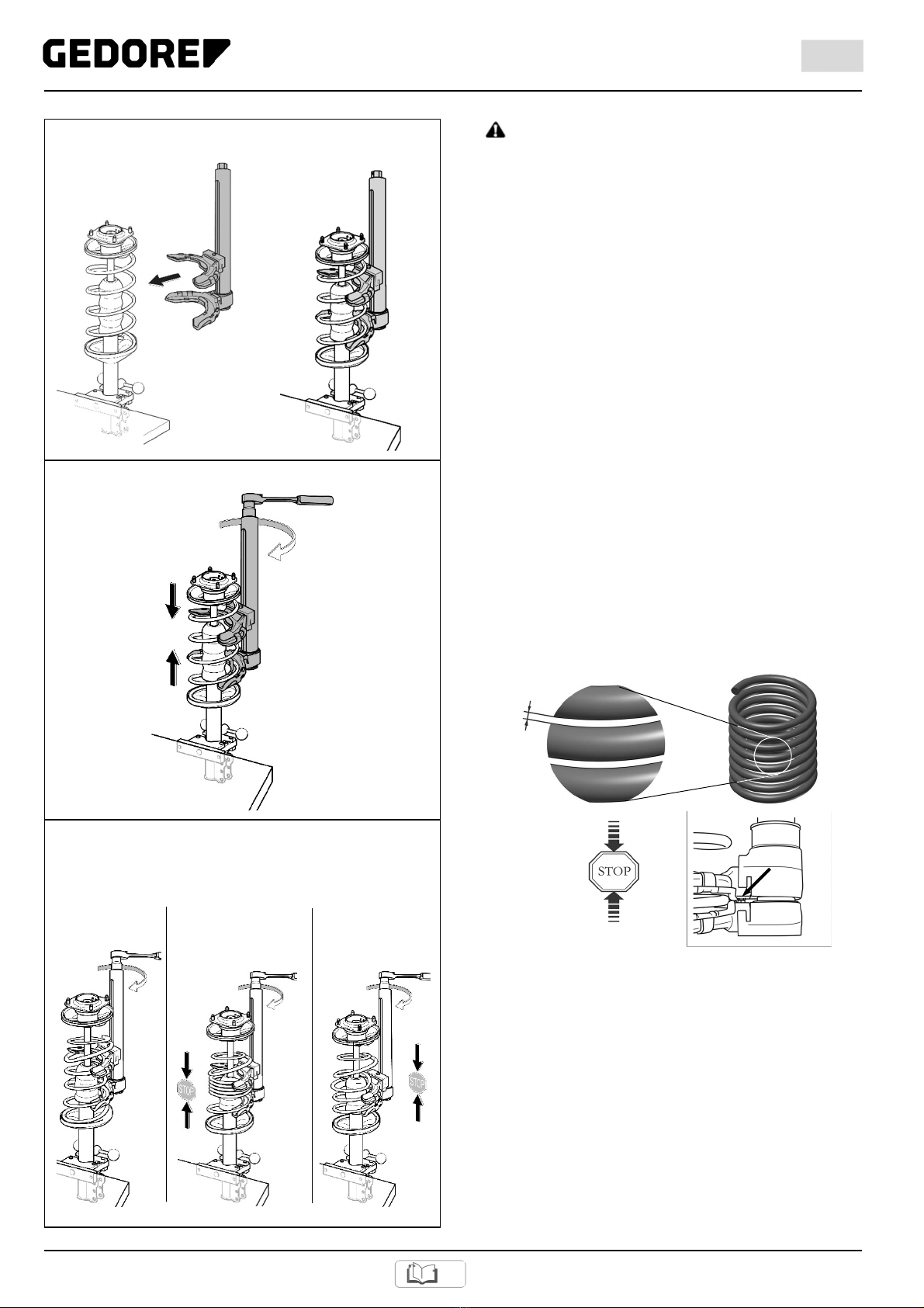
The examples show two different techniques which are to be applied
depending on the type of jaws used. (Fig. 7)
Technique 1: Removing and installing a spring using the jaws that
engage the spring coils.
Technique 2: Removing and installing a spring using the special jaw
that encompasses the upper spring plate.
Note: Compressing a rear axle spring on the vehicle can be carried out
according to the same principle as described in technique 1. The
procedure is similar, however, with the difference that
dismantling/reassembling the suspension/damper strut is not necessary.
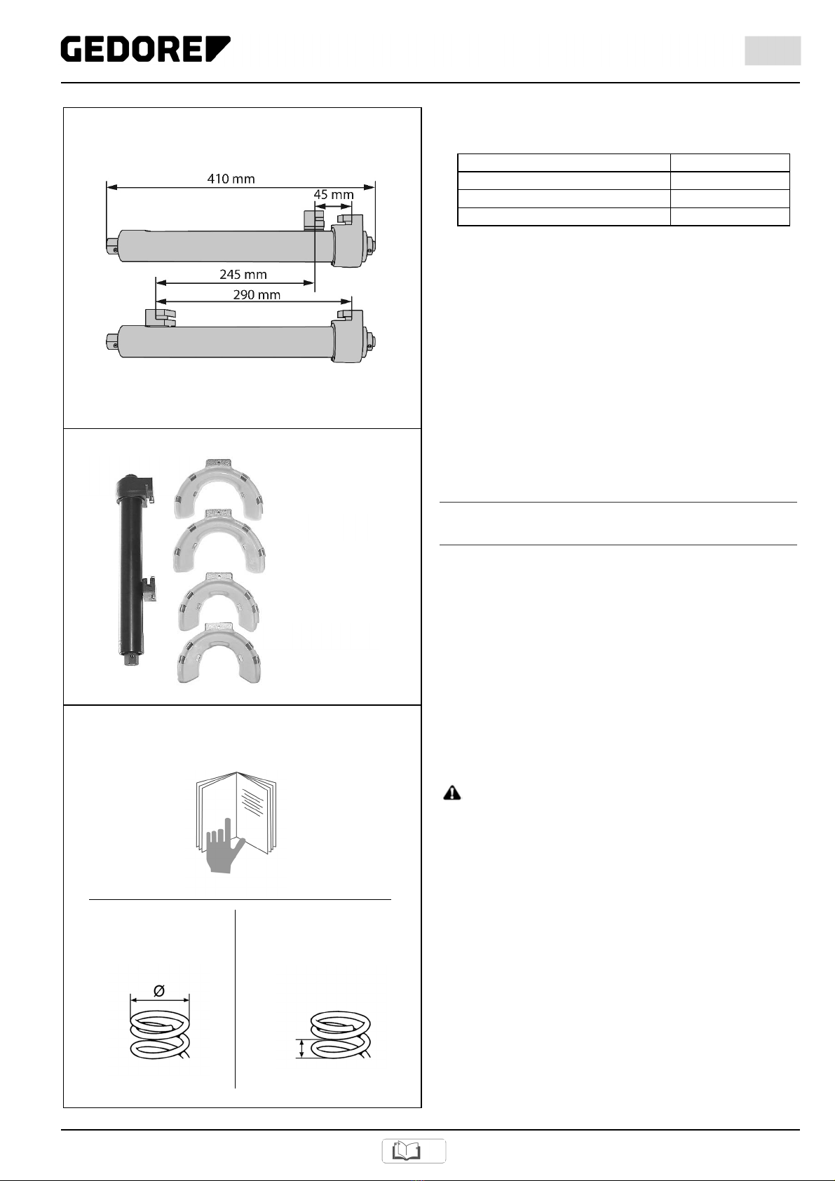
During the whole compression and decompression processes, pay
attention to the space available. Make sure that the base body and the
jaws do not touch the vehicle/car body parts, and that they are not
pushed against these.
DANGER
Considerable forces are exerted when springs are being compressed.
Strictly adhere to the following instructions. Non-observance can lead to
hazardous situations such as breakage of the spring compressor
resulting in debris/parts or the spring becoming projectiles.
Never use the spring compressor if it is damaged or defective.
Never use a hammer on the tool.
Lubricate the spindle with molybdenum disulphide paste, for example
KL-0014-0030.
Only use molybdenum disulphide paste, for example KL-0014-0030,
as lubricant.
Only use Original GEDORE Automotive spare parts.
ATTENTION
Stop turning the drive nut once the spring compressor has reached its
limit stop (that is when the mobile jaw mount has been slid against the
fixed one until limit stop). Failure to do so will result in damage to the
spring compressor.
Once the spring compressor has reached its limit stop, that is when
the mobile jaw mount has been slid against the fixed one until limit
stop, make sure that the drive nut is rotated only in the opposite
direction.
Note: Always perform all work on the vehicle/vehicle components in
strict compliance with the directions, provisions, and safety regulations
specified by the vehicle manufacturer.
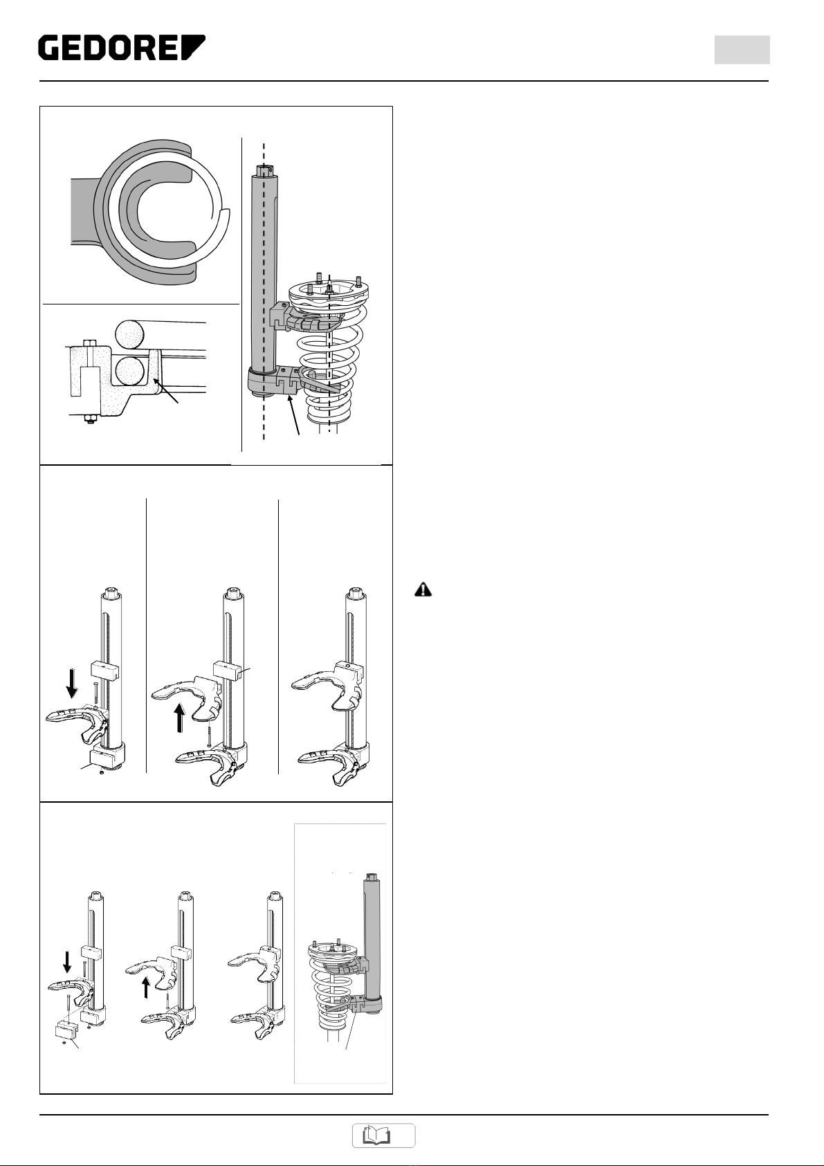
4.1 Clamping a Suspension-/Damper Strut
into the holding fixture.
DANGER
Suspension-/damper struts that are not properly fixed can come
loose and fall off the spring compressor while the spring is being
compressed.
Do not clamp neither the suspension-/damper strut nor the spring
compressor into a vice.
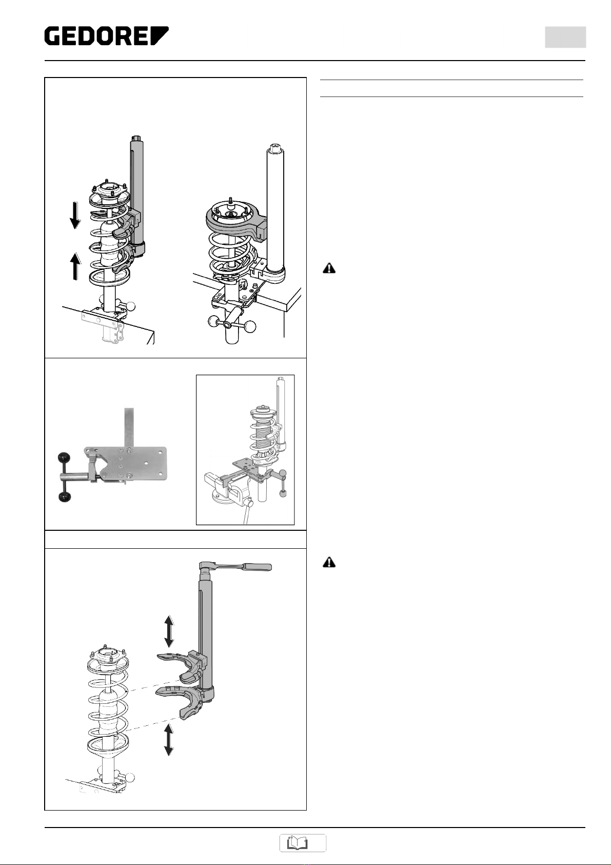
Clamp the removed suspension-/damper strut into holding fixture
KL-0055-60 (accessory). (See Fig. 8)
4.2 Removing a Spring
Technique 1: Removing a spring using the jaws that
engage the spring coils.
1.
ATTENTION
When opening the jaws, there is a risk of damage to the base body.
When opening the jaws on the base body, make sure that there is
no pressure being exerted on the limit stop once the maximum
opening distance has been reached.
(Stop turning the drive nut counter-clockwise.)
Using a 1/2" reversible ratchet with a 24mm (waf) socket, turn the
drive nut and adjust the spring compressor so as to enable it to grasp
and compress as many coils as possible. (Fig. 9)
Fig. 7: Compressing a spring.
Technique 1: Technique 2:
Compressing a spring Compressing a spring via
via the spring coils. the upper spring plate.
Fig. 8: Clamping the suspension-/damper strut into
holding fixture.
Removing a Spring (Technique 1)
Fig. 9: Preadjusting the spring compressor.
(see Fig. 16)
KL-0055-60
Holding Fixture (Accessory)