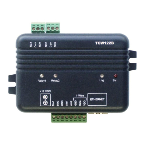
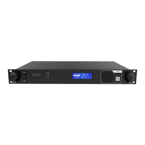
Teracom TCW180B User manual

Ethernet controller TCW180B
Users manual
1. Short description
TCW180B is 8-channel Ethernet relay board, which is designed to work in IP-based networks
and managed by WEB interface or SNMP rograms. This device can be used as standalone or as a
art of control and monitoring systems. Its I/O interface - 8 relay out uts and 1 digital in ut, is
suitable for solving s ecific roblems in various fields such as remote control, rocess automation,
home automation and others.
2. Features
•10 Mb Ethernet connectivity;
•Password rotected web based configuration and control;
•1 digital in ut with "logic level" and "dry contact" modes;
•8 relays with NO and NC contacts;
•SNMP v.1, ICMP and VLAN su ort;
•Sending SNMP Tra s messages under certain conditions;
•Sending E-mail messages under certain conditions;
•SMTP with authorization (SSL is not su orted);
•MAC Address filtering;
•Remote FTP firmware u date.

3. Technical parameters
Supply voltage, VDC
12 ± 2
Maximum current ( with all relays ON), mA 70
Weight, g 205
Dimensions, mm 115 x 90 x 40
Operating temperature, °C 0 ÷ 40
Minimum high level input voltage for digital input, VDC 2.5
Maximum low level input voltage for digital input, VDC 0.8
Maximum input voltage for digital input, VDC 5.5
Maximum switchable current (at 220 VAC) , А 1
Maximum switchable voltage, VAC/VDC 250/110
4. Connectors
In uts and out uts locations are shown below:
•J1 – digital in ut mode selection jum er – dry contact (close) and logic level (o en);
• ETHERNET – RJ45 connector;
• POWER – ø 2mm ower connector, central ositive;
• I/O – screw ty e terminals.
5. LED indicators
The following indicators show the status of the controller:
•Relay 1 to 8 status (green) – the LED illuminates whenever the corres onding relay is
activated;

•Power (red) – this flashes when the ower su ly is turned on;
•Busy (yellow) – this LED indicates that someone is connected to the controller through
web interface;
• Link (green) – this LED is located on the Ethernet connector. It indicates that the device is
connected to the network ;
•ct (yellow) – this LED is located on the Ethernet connector. It flashes when activity is
detected on the network.
6. Example pplication
6.1 Remote control
The controlled device is connected in series with the relay contacts. User can o erate
TCW180B using a web browser or SNMP a lication. The relays can be managed inde endently of
each other.
7. Installation
Please follow the ste s below for ro er installation :
1. Mount the controller in a dry and ventilated lace.
2. Connect the Ethernet ort to a 10/100MB Ethernet network. For direct connection to a PC
use a “crossover” cable.
3. Connect the I/O ins of the controller according to the required a lication.
4. Connect the ower su ly.
If the red LED blinks, the ower su ly is OK. By default TCW180B comes with the following
network settings:
IP address: 192.168.1.2, Subnet Mask: 255.255.255.0, Default Gateway: 192.168.1.1
Communication with TCW180B can be established by assigning a tem orary IP address to the
com uter. This address should be in the same network (for exam le 192.168.1.3). To get access to the
web interface, you should ty e htt ://192.168.1.2 into the browser.

If the network settings are correct, the “Login” age will a ear.
8. Web-based setup.
The web based interface allows configuration, monitoring and control. Recommended browser is
Internet Ex lorer at 1024x768 resolutions.
8.1 Login page
After o ening the “Login” age, authorization data must be entered (by default username=admin
, assword=admin). It is recommended to change the username and assword to revent unauthorized
access to the controller.
The controller su orts only one active session – only one user can o erate the device. If another
user tries to login, the following message a ears: “Someone’s logged in”:
The active session will be terminated automatically, if the current user stays inactive for 2 minutes.
8.2 Monitoring page
After successful authorization, the “Monitoring” age a ears:

The “Monitoring” age rovides information about the state of the relays and digital in ut.
The state of the relay can be changed by a ro riate “ON/OFF” button. To change the state of
relay for a while, “Pulse” button should be ressed. Duration of the ulse is s ecified in “Pulse Duration”
field of “I/O Setu ” age.
Three buttons are located on the bottom of the age:
•“All ON” – click on this button will turn all relays ON
•“All OFF” – click on this button will turn all relays OFF
•“Pulse All” – click on this button will change the states of all relay out uts for a time,
s ecified in “Pulse Duration” field of “I/O Setu ” age.
8.3 ccount page
In this age authentication details for WEB access to TCW180B can be set. Only one user is
su orted.
8.4 Network Setup page
The Network arameters are set on this age.
For “IP configuration” and “MAC address” section, following arameters can be changed:
•IP configuration – IP Address can be static or dynamic (DHCP server should be resent in
the network);

•IP address, Subnet mask , Default gateway – these fields are active if IP address is static;
•Host Name – u to 16 symbols, it a ears as a “Subject” in sent e-mails;
•M C – device MAC address.
The good ractice is to change the default IP address of controller immediately after first ower-
on. This will avoid collisions if many devices are used in the same network. It may be necessary to clear
the ar cache, each time you connect a new device to the network. This is done by ty ing arp -d in the
command rom t window of com uter.
VLAN and MAC address filtering are su orted. U to 3 MAC addresses (including Default
Gateway) can be active in MAC filtering.
ttention! If you are not familiar with VLAN and MAC filtering leave these sections by default.
To set u the SMTP server details, the following fields should be com leted:
•Mail server [IP:port] – domain or IP address + ort of SMTP mail server. To use domain
name, IP address in field DNS must be correct;
•E-mail – sender e-mail;
•Username and Password – authentication details for mail server.
Mail server is considered server for sending mails. Secure Socket Layer is not su orted.

8.5 SNMP Setup page
TCW180B su orts SNMP v.1 that enables tra delivery to an SNMP management a lication.
This enables the device to be art of large monitoring and control networks. The ossible settings for
“SNMP” section are:
•SNMP Configuration – enable/disable SNMP;
•Read-Write community – erforms client authentication;
•Read-Only community – erforms client authentication;
•SNMP Traps – enable/disable SNMP tra messages;
•IP address – IP address of the receiving host
•Community string – erforms client authentication
•Trap Interval - time interval in seconds for SNMP tra messages;
•Max. Traps number – maximum number of SNMP tra messages sent, if tra condition is
resent
SNMP tra s are sent if:
•event occurs (status change) on Digital In ut;
•restart condition.
8.6 I/O Setup page
The following arameters can be set for the relays:
•Descri tion – brief descri tion of the out ut, maximum 10 characters can be used;
•Pulse Duration – time for relay activation when "Pulse" button on "Monitoring" age is
ressed. This setting a lies to all 8 relays.

Every change of state for Digital In ut can mange e-mail sending. Following arameters must be
set: •Mail to – e-mail address of reci ient;
•Subject – e-mail subject;
•Message – e-mail body.
Important! It is necessary to set SMTP server settings on "Network Setu " age, to successfully
send e-mail messages.
In the exam le above, if an event occurs (closing contact) the controller will send e-mail message
9.
SNMP setup
TCW180B can be configured and monitored through SNMP (Sim le Network Management
Protocol). This could be done using every SNMPv.1 com atible rogram.Parameters that can be
changed, are grou ed according to their functions in the tables below. To obtain a valid OID number
it is necessary to re lace the “x” symbol with the ”1.3.6.1.4.1.38783”. To save the changes
configurationSaved (OID x.8.0) should be set to "1".
9.1 Product
OID Name Access Description Syntax
x.1.1.0 name read-only Device name String
x.1.2.0 version read-only Software version String
x.1.3.0 date read-only Release date String
9.2 SNMP Setup
OID Name Access Description Syntax
x.2.1.0 trapEnabled read-write RAP messages enable/disable IN EGER { Yes(1), No(0) }
x.2.2.0 trapReceiverIPAddress read-write RAP messages receiver address IpAddress
x.2.3.0 trapCommunity read-write RAP community String (SIZE (0..13))
x.2.4.0 trapInterval read-write RAP messages interval IN EGER (0..255)
x.2.5.0 maxNumberOf raps read-write Maximum number SNMP messages IN EGER (0..255)
9.3 Monitor and control
OID Name Access Description Syntax
x.3.1.0 digitalInput read-only Digital input state IN EGER { High(1), Low(0) }
x.3.2.0 Relay1 read-write Relay 1 state IN EGER { ON(1), OFF(0) }
x.3.3.0 Relay2 read-write Relay 2 state IN EGER { ON(1), OFF(0) }
x.3.4.0 Relay3 read-write Relay 3 state IN EGER { ON(1), OFF(0) }
x.3.5.0 Relay4 read-write Relay 4 state IN EGER { ON(1), OFF(0) }
x.3.6.0 Relay5 read-write Relay 5 state IN EGER { ON(1), OFF(0) }
x.3.7.0 Relay6 read-write Relay 6 state IN EGER { ON(1), OFF(0) }
x.3.8.0 Relay7 read-write Relay 7 state IN EGER { ON(1), OFF(0) }
x.3.9.0 Relay8 read-write Relay state IN EGER { ON(1), OFF(0) }
x.3.10.0 Pulse1 read-write Relay 1 pulse state SYN AX IN EGER (0..255)

x.3.11.0 Pulse2 read-write Relay 2 pulse state SYN AX IN EGER (0..255)
x.3.12.0 Pulse3 read-write Relay 3 pulse state SYN AX IN EGER (0..255)
x.3.13.0 Pulse4 read-write Relay 4 pulse state SYN AX IN EGER (0..255)
x.3.14.0 Pulse5 read-write Relay 5 pulse state SYN AX IN EGER (0..255)
x.3.15.0 Pulse6 read-write Relay 6 pulse state SYN AX IN EGER (0..255)
x.3.16.0 Pulse7 read-write Relay 7 pulse state SYN AX IN EGER (0..255)
x.3.17.0 Pulse8 read-write Relay pulse state SYN AX IN EGER (0..255)
x.3.18.0 allOn read-write Set all relays On SYN AX IN EGER (0..255)
x.3.19.0 allOff read-write Set all relays Off SYN AX IN EGER (0..255)
x.3.20.0 allPulse read-write Pulse all relays SYN AX IN EGER (0..255)
9.4 Network
OID Name Access Description Syntax
x.4.1.0 deviceIPAddress read-write Device IP address IpAddress
x.4.2.0 subnetMask read-write Subnet Mask IpAddress
x.4.3.0 gateway read-write Gateway IpAddress
x.4.4.0 deviceMACAddress read-write Device MAC Address OC E S RING (SIZE(6))
x.4.5.0 dhcpConfig read-write DHCP ON/OFF IN EGER { ON(1), OFF(0) }
x.4.6.1.1.0 filterMACAddress1 read-only MAC Filter 1 (Gateway) OC E S RING (SIZE(6))
x.4.6.1.2.0 filterMACEnable1 read-write MAC Filter 1 ON/OFF IN EGER { ENABLED(1), DISABLED(0) }
x.4.6.2.1.0 filterMACAddress2 read-write MAC Filter 2 OC E S RING (SIZE(6))
x.4.6.2.2.0 filterMACEnable2 read-write MAC Filter 2 ON/OFF IN EGER { ENABLED(1), DISABLED(0) }
x.4.6.3.1.0 filterMACAddress3 read-write MAC Filter 3 OC E S RING (SIZE(6))
x.4.6.3.2.0 filterMACEnable3 read-write MAC Filter 3 ON/OFF IN EGER { ENABLED(1), DISABLED(0) }
x.4.7.1.0 VLANStatus read-write VLAN status IN EGER { ENABLED(1), DISABLED(0) }
x.4.7.2.0 VlanId read-write VLAN ID IN EGER (0..4095)
x.4.8.1.0 smtpServer read-write SM P Server IP address IpAddress
x.4.8.2.0 smtpPort read-write SM P Server Port IN EGER (0..65535)
x.4.8.3.0 smtpSenderEmail read-write SM P Sender e-mail address String (SIZE (0..39))
9.5 I/O Setup
OID Name Access Description Syntax
x.5.1.0 relayPulseDuration read-write Global Pulse duration IN EGER (0..255)
x.5.2.0 Relay1description read-write Relay 1 description String (SIZE (0..10))
x.5.3.0 Relay2description read-write Relay 2 description String (SIZE (0..10))
x.5.4.0 Relay3description read-write Relay 3 description String (SIZE (0..10))
x.5.5.0 Relay4description read-write Relay 4 description String (SIZE (0..10))
x.5.6.0 Relay5description read-write Relay 5 description String (SIZE (0..10))
x.5.7.0 Relay6description read-write Relay 6 description String (SIZE (0..10))
x.5.8.0 Relay7description read-write Relay 7 description String (SIZE (0..10))
x.5.9.0 Relay8description read-write Relay 8 description String (SIZE (0..10))
x.5.10.0 digitalInputAction read-write Digital Input Action condition
IN EGER { FALLING(2),RISING(1),
DISABLED(0) }
x.5.11.0 digitalInput o read-write
Digital Input event receiver's e
-
mail
address String (SIZE (0..38))
x.5.12.0 digitalInputSubject read-write Digital Input event e-mail's subject String (SIZE (0..11))
x.5.13.0 digitalInputBody read-write Digital Input event e-mail's body String (SIZE (0..22))
x.6.0 configurationSaved read-write
Configuration save status
SAVED/UNSAVED IN EGER { SAVED(1), UNSAVED(0) }
x.7.0 restartDevice read-write Restart Device IN EGER { RES AR (1), CANCEL(0) }

10.Restoring Factory Default Settings
If the IP address or assword is forgotten, TCW180B can be restored to its original factory default
settings. To do this, lease follow the ste s below:
• Turn off the ower su ly from the unit;
• Press and hold the RESET button then turn on the ower su ly;
•The LED’s Power and Busy will flash 14 times, after that they will turn on. In this moment the
RESET button should be released.
The factory default settings are:
User Name (Admin) admin
Password (Admin) admin
IP Address 192.168.1.2
Subnet Mask 255.255.255.0
Default Gateway 192.168.1.1
SNMPConfiguration disabled
readCommunity ublic
writeCommunity rivate
11.Firmware update
TCW180B su orts remote firmware u date. To u date the device follow the ste s below:
-Download the TCW1XX_Update_Tool rogram from www.teracom.cc;
-Download the latest firmware version file (*.cod) from www.teracom.cc;
-Start the rogram and u date the firmware.
ttention! Don’t turn off the power supply during the update. Turning off the power supply will
damage the device.
Rev. 2 – October 2011
Table of contents
Other Teracom Controllers manuals
Popular Controllers manuals by other brands
Santerno
Santerno SINUS PENTA Series Guide
Baelz Automatic
Baelz Automatic 373-E66 Series operating instructions

Digital Monitoring Products
Digital Monitoring Products X1 Series quick start guide

Evco
Evco Vcolor 679 Installer manual
Athena
Athena 16C series user guide
SmartLine
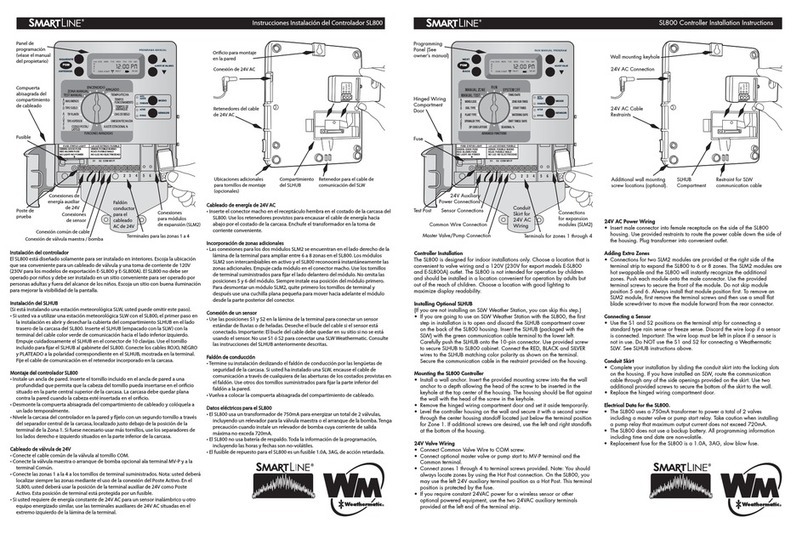
SmartLine SL800 installation instructions

