Terra Universal Product Manual
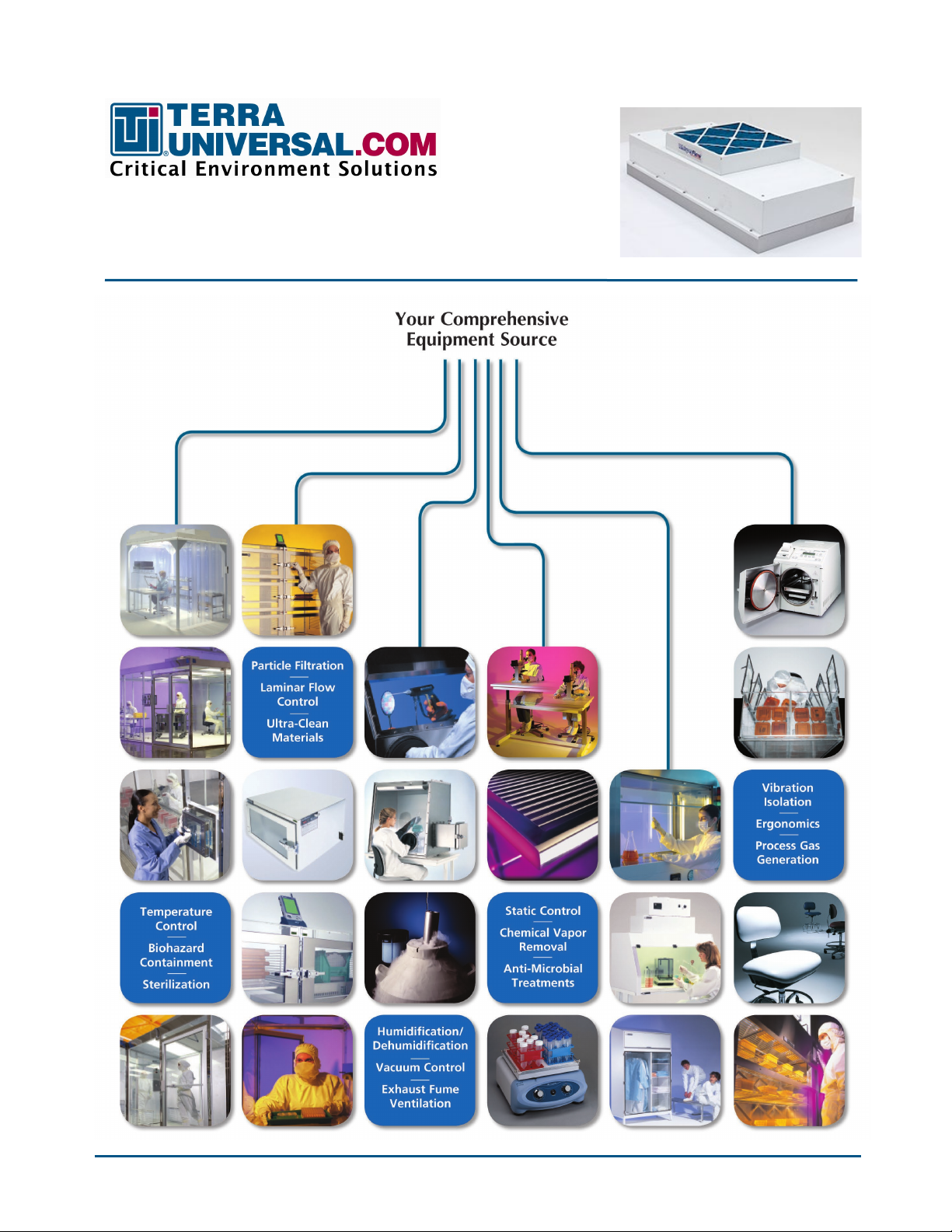
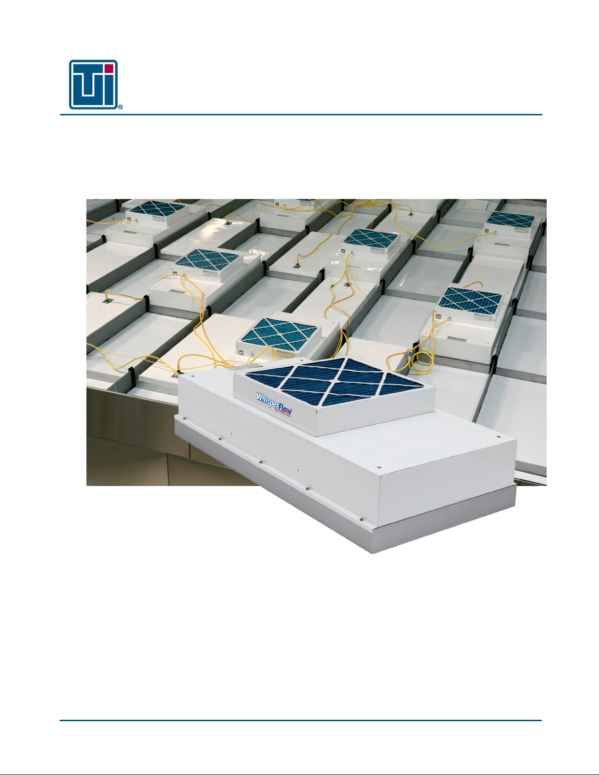
WhisperFlow® Fan Filter Units
© Copyright 2021 Terra Universal Inc. All rights reserved.
Terra Universal, Inc. • TerraUniversal.com • 800 S. Raymond Ave. • Fullerton, CA 92831 • TEL: (714) 578-6000 • FAX: (714) 578-6020 5
2. Safety
To reduce the risk of fire, electric shock, or injury to persons, observe the following:
•Do not use this unit for anything other than the intended manner of the manufacturer. Contact the manufacturer for
additional clarification.
•Before servicing the unit, or replacing a filter, switch power to OFF at the service panel and lock it to prevent
accidental power activation. When the panel cannot be locked, securely fasten a prominent warning device, such as a
tag, to the service panel.
•When the removal/disconnection of either filter is required due to service or component replacement, the
replacements are to be remounted as previously installed.
•Qualified person(s) must install the unit and configure the electrical wiring adhering to all applicable codes and
standards, which includes fire-rated construction. All metal components must be properly grounded.
•Do not damage or interfere with electrical wiring and other hidden utilities when cutting or drilling into the wall or
ceiling.
•Check the ECM unit’s supply cord for damage, if it is damaged it must be replaced by the manufacturer, its service
agent, or similarly qualified persons to avoid a hazard.
Critical Operation Conditions
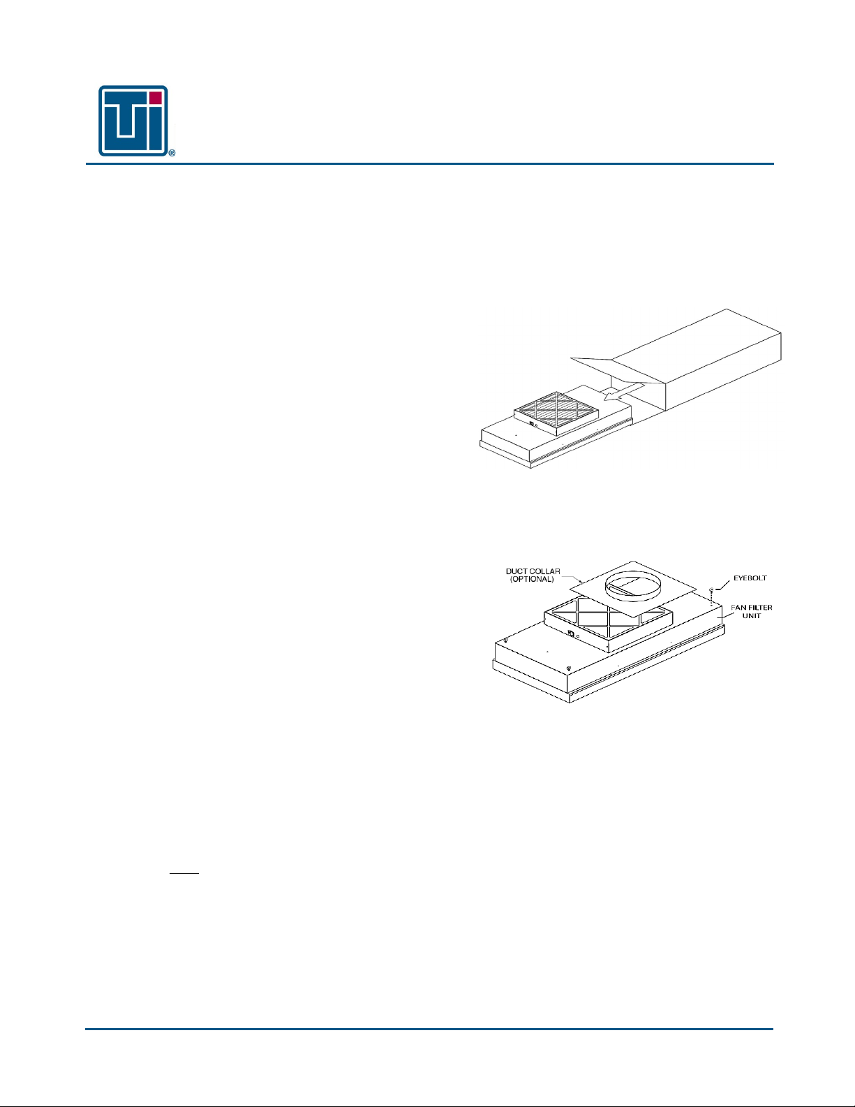
•The filter media is extremely sensitive and can damage easily. The screen only protects against an accidental ‘touch’
of the filter media. Avoid touching and damaging the HEPA filter because the warranty will void.
•Never place anything on the filter. Always place filter on its side to avoid damage.
This manual pertains to proprietary devices manufactured by
Terra Universal, Inc. Neither this document nor any portion of
it may be reproduced in any way without prior written
permission from Terra Universal.
A thorough familiarity with all operating guidelines is essential to safe operation of
the product. Failure to observe safety precautions could result in poor
performance, damage to the system or other property, or serious bodily injury or
death. The following symbols are intended to call your attention to two levels of
hazard involved in operation.
Terra Universal makes no warranties applying to information
contained in this manual or its suitability for any implied or
inferred purpose. Terra Universal shall not be held liable for
any errors this manual contains or for any damages that
result from its use.
Cautions are used when failure to observe instructions could result in
significant damage to equipment.
Warnings are used when failure to observe instructions or precautions
could result in injury or death.
The information presented here is subject to change without notice.