TERRAIN VANROVE 04620V User manual

1
READ THIS MANUAL IN ITS ENTIRETY BEFORE ASSEMBLING OR USING THIS PRODUCT.
RANGE BLIND ASSEMBLY INSTRUCTIONS
Part Number: 04620V
www.terrainoutdoor.com
(989) 575-3122

ATTENTION! DO NOT RETURN TO RETAILER. IF THERE ARE ANY MISSING OR BROKEN COMPONENTS
PLEASE CONTACT THE MANUFACTURER AT (989) 575-3122. REFERENCE BLIND MODEL: RANGE 04620V AND THE
SPECIFIC COMPONENTS NAME FROM THE PARTS LIST.
2
READ THIS MANUAL IN ITS ENTIRETY BEFORE ASSEMBLING OR USING THIS PRODUCT.
RANGE BLIND USAGE INSTRUCTIONS AND WARNINGS
Thank you for your purchase of this Terrain Outdoor® Hunting Blind
product. To ensure your personal safety, please take a moment to
carefully read this Instruction Manual in its entirety before
attempting to set-up, install, remove and/or otherwise use this
Terrain Outdoor® Hunting Blind product(s). Failure to follow these
instructions may result in serious injury or death!
If you have any questions about the installation, removal, and/or
use of this product, or any other Terrain Outdoor® product(s) do
not hesitate to call one of our customer service representatives at
(989) 575-3122 or feel free to visit us online at
www.terrainoutdoor.com. Our customer service representatives
will answer any questions you may have about any of the complete
line of Terrain Outdoor® products.
If you find damaged or missing parts in a newly purchased product,
please contact the manufacturer at (989) 575-3122 for
replacements.
Please note that WARNING! Statements have been placed
throughout this Instruction Manual. These statements point out
important safety information and instructions, which, if not
followed could endanger the personal safety and/or property of
the operator(s). It is imperative that the operator(s) of this product,
or any other Terrain Outdoor® product(s) read and follow all the
instructions and warnings contained in this Instruction Manual
prior to attempting to use this Terrain Outdoor® product(s), or any
other Terrain Outdoor® product(s). Failure to comply with these
instructions and/or warnings may result in serious personal injury
or death!
WARNING! Failure to read and strictly comply with the instructions
contained in this Instruction Manual may result in serious injury or
death!
WARNING! Prior to each hunt, you must inform someone of your
hunting location, including the specific location of your blind and
the expected duration of your hunt. Failure to follow these
instructions may result in serious injury or death!
WARNING! The safe use and operation of this product(s) is the sole
responsibility of the user. It is also the sole responsibility of the
owner to provide any person(s) who borrow or purchase this
product(s) with these instructions. Failure to follow these
instructions may result in serious injury or death!
WARNING! Prior to each hunt, make sure that you have a signaling
device (e.g., mobile phone, radio, whistle, signal flare or Personal
Locator Device (PLD) in your possession and in an operable
condition. This device must be within easy access shall you
experience the need to contact emergency assistance. Failure to
follow these instructions may result in serious injury or death!
WARNING! This product(s) is designed for adult use only. No one
under the age of 16 shall attempt to use this or any other product(s)
without direct adult supervision. Failure to follow these
instructions may result in serious injury or death!
WARNING! DO NOT modify, fix/repair, alter, bend, cut, weld, drill,
or heat the blind in any way without explicit authorized and written
instructions from the manufacturer. Additionally, do not attach
anything to your blind without explicit authorized and written
instructions from the manufacturer. Failure to follow these
instructions may result in voided warranty, serious injury, or death!
WARNING! Never use any kind of fuel-burning products (heaters,
lanterns, etc.) inside this enclosure. Use of fuel burning products
can result in dangerous concentrations of carbon monoxide, a
colorless and odorless gas. Breathing carbon monoxide will cause
serious injury or death.
WARNING! Always use hearing protection when discharging
firearms, especially within an enclosed space.
WARNING! This product is not fireproof. The plastic will burn if it
comes into contact with an open flame or fuel source. Keep
product away from direct flame. Failure to follow these instructions
may result in serious injury or death!
WARNING! This product is for hunting purposes only! It is not to be
used as a camping tent or for any other function. Failure to follow
this warning may result in serious injury or death!
WARNING! Practice safe and proper firearms handling while using
this product. Keep firearm or weapon unloaded until seated in the
blind and no further movement is expected. Unload the firearm or
weapon prior to exiting the blind. Failure to follow this warning
may result in serious injury or death!
WARNING! Practice safe and proper firearms handling while using
this product. Keep firearm pointed in the direction of least
consequence with the safety ON in SAFE position at all times.
Failure to follow this warning may result in serious injury or death!
California Prop 65 Warning: This product may contain a chemical known
to the state of California to cause cancer, birth defects, or other
reproductive harm.
If you have any questions about the assembly, installation or
use of this product, or any other product, please do not
hesitate to call one of our customer service representatives at
(989) 575-3122 and they will answer all questions you may
have about any of the complete line of products. Please have
the product model number (04620V) and component part
number ready before calling to better assist you.

ATTENTION! DO NOT RETURN TO RETAILER. IF THERE ARE ANY MISSING OR BROKEN COMPONENTS
PLEASE CONTACT THE MANUFACTURER AT (989) 575-3122. REFERENCE BLIND MODEL: RANGE 04620V AND THE
SPECIFIC COMPONENTS NAME FROM THE PARTS LIST.
3
READ THIS MANUAL IN ITS ENTIRETY BEFORE ASSEMBLING OR USING THIS PRODUCT.
PARTS LIST
Part # Description Qty
2020 Bolt (¼-20 x 1-¼") 51
2023 Bolt (10-32 X ¾”) 11
6014 Nut (10-32 Lock Nut) 11
3013 Washer (¼ID Rubber) 11
3014 Washer (¼ ID ⅝ OD) 51
6013 Wing Nut (¼-20) 51
INS-TERRAIN-HANDLE Door Handle 1
INS-TERRAIN-TURN-BUTTON Window Latch 10
03864V-A Common Sidewall 4
04627V-A Door/Frame Assembly 1
03866V-C Roof Panel 5
04630V Roof Cap 1
INS-COMMON TAB PLEXIGLASS Windows 5
INS-COMMON LIVING HINGE Window Hinge 5
SPECS
Size: 76”x76”x85” (LxWxH)
Weight: 114 lbs
Maximum Occupancy: One adult with gear
Color: Olive drab exterior, black interior
TOOLS NEEDED
Phillips Screw Driver
⅜” Socket Wrench OR Adjustable Crescent Wrench
STORAGE AND CARE
All Terrain Outdoor® hunting blinds are made with an
industrial grade UV Protected High Density Polyethylene
material. All components and hardware is resistant to sun,
moisture, and normal temperature fluctuation. This product has
a 1 year limited warranty against defects in materials and
workmanship.
To extend the life of this product, keep out of prolonged
exposure to sunlight in a shaded area. Keep in an area away
from high winds. Make sure that all windows and the door are
closed tightly when not in use.
To remove surface blemishes and stains use a wet rag and mild
detergent as needed. Rinse well. Bleach based cleaners may be
used sparingly on the wall, roof, and door panels to remove
stains - AVOID WINDOWS. Use only a non-abrasive cloth and a
cleaner labeled for use with Acrylic or Plexiglass to clean the
windows.

ATTENTION! DO NOT RETURN TO RETAILER. IF THERE ARE ANY MISSING OR BROKEN COMPONENTS
PLEASE CONTACT THE MANUFACTURER AT (989) 575-3122. REFERENCE BLIND MODEL: RANGE 04620V AND THE
SPECIFIC COMPONENTS NAME FROM THE PARTS LIST.
4
READ THIS MANUAL IN ITS ENTIRETY BEFORE ASSEMBLING OR USING THIS PRODUCT.
INCLUDED ITEMS AND
HARDWARE LIST
Check to make sure you have all the required parts and hardware. If
you find damaged or missing parts in a newly purchased product,
please contact the manufacturer at (989) 575-3122 for replacements.
Part # Description Qty
2020 Bolt (¼-20 x 1-¼") 51
2023 Bolt (10-32 X ¾”) 11
6014 Nut (10-32 Lock Nut) 11
3013 Washer (¼ID Rubber) 11
3014 Washer (¼ ID ⅝ OD) 51
6013 Wing Nut (¼-20) 51
INS-TERRAIN-HANDLE Door Handle 1
INS-TERRAIN-TURN-BUTTON Window Latch 10
Part # Description Qty
03864V-A Common Sidewall 4
04627V-A Door/Frame Assembly 1
03866V-C Roof Panel 5
04630V Roof Cap 1
INS-COMMON TAB PLEXIGLASS Windows 5
INS-COMMON LIVING HINGE Window Hinge 5

ATTENTION! DO NOT RETURN TO RETAILER. IF THERE ARE ANY MISSING OR BROKEN COMPONENTS
PLEASE CONTACT THE MANUFACTURER AT (989) 575-3122. REFERENCE BLIND MODEL: RANGE 04620V AND THE
SPECIFIC COMPONENTS NAME FROM THE PARTS LIST.
5
READ THIS MANUAL IN ITS ENTIRETY BEFORE ASSEMBLING OR USING THIS PRODUCT.
FIG 2
FIG 1
03864V
-
A
03864V
-
A
2022
3014,
6013
STEP 1:
Attach (2) common sidewall [
03864V
-
A
] panels
together using (5) Bolt ¼-20 x 1-¼" [2020], (5) Washer ¼
ID ⅝ OD [3014], and (5) Wing Nut ¼-20 [6013].
NOTE: When assembling, be sure that the bolt is inserted
from the exterior and the washer and wingnut are from
the interior. Make sure window openings are all towards
the top of the assembly.
STEP 2: Repeat STEP 1 to attach the 3 other common
sidewall [03864V-A].
(4
x)
03864V
-
A
DETAILED VIEW
(10x) 3014, 6013, 2020
2020

ATTENTION! DO NOT RETURN TO RETAILER. IF THERE ARE ANY MISSING OR BROKEN COMPONENTS
PLEASE CONTACT THE MANUFACTURER AT (989) 575-3122. REFERENCE BLIND MODEL: RANGE 04620V AND THE
SPECIFIC COMPONENTS NAME FROM THE PARTS LIST.
6
READ THIS MANUAL IN ITS ENTIRETY BEFORE ASSEMBLING OR USING THIS PRODUCT.
FIG 4
FIG 3
3014,
6013
2020
DETAILED VIEW
03864V
-
A
03864V
-
A
04627V
-
A
03864V
-
A
STEP
3
:
Attach (1)
Door/Frame Assembly
[
0
04627V
-
A
]
panels to the assembly using (5) Bolt ¼-20 x 1-¼" [2020],
(5) Washer ¼ ID ⅝ OD [3014], and (5) Wing Nut ¼-20
[6013].
STEP
4
:
Finish fastening the
Door/Frame Assembly
[04627V-A] panels to the assembly using (5) Bolt ¼-20
x 1-¼" [2020], (5) Washer ¼ ID ⅝ OD [3014], and (5) Wing
Nut ¼-20 [6013].
NOTE: When assembling, be sure that the bolt is inserted
from the exterior and the washer and wingnut are from
the interior.
(4
x)
03864V
-
A
(10x)
3014, 6013, 2020
04627V
-
A
03864V
-
A

ATTENTION! DO NOT RETURN TO RETAILER. IF THERE ARE ANY MISSING OR BROKEN COMPONENTS
PLEASE CONTACT THE MANUFACTURER AT (989) 575-3122. REFERENCE BLIND MODEL: RANGE 04620V AND THE
SPECIFIC COMPONENTS NAME FROM THE PARTS LIST.
7
READ THIS MANUAL IN ITS ENTIRETY BEFORE ASSEMBLING OR USING THIS PRODUCT.
FIG 5
FIG 6
STEP
5
:
Lay each section of the (5) Range Roof
Panel [03866V-C] so they overlap each other
with the holes lined up, small ribs inside the
large ribs. Fasten the (5) Range Roof Panels to
the assembly using (5) Bolt ¼-20 x 1-¼" [2020],
(5) Washer (¼ID Rubber) [3013], and (5) Wing
Nut ¼-20 [6013]. Fasten only through the
OUTSIDE HOLES on each side. Do not tighten all
the way.
STEP 6: Locate the Range Roof Cap [04630V]
and align the roof cap over the center of the
roof assembly. The roof assembly will be
required to be standing on its side. Then
attach the roof cap with (5) Bolt ¼-20 x 1-¼"
[2020], (5) Washer (¼ID Rubber) [3013], and (5)
Wing Nut ¼-20 [6013]. Once the bolts are in
place, tighten down.
NOTE: When assembling, be sure that the bolt
is inserted from the exterior and the washer and
wingnut (NOT SHOWN IN PICTURES) are from
the interior.
DETAILED VIEW
6013
, 3014
(NOT SHOWN INTERIOR)
2020

ATTENTION! DO NOT RETURN TO RETAILER. IF THERE ARE ANY MISSING OR BROKEN COMPONENTS
PLEASE CONTACT THE MANUFACTURER AT (989) 575-3122. REFERENCE BLIND MODEL: RANGE 04620V AND THE
SPECIFIC COMPONENTS NAME FROM THE PARTS LIST.
8
READ THIS MANUAL IN ITS ENTIRETY BEFORE ASSEMBLING OR USING THIS PRODUCT.
FIG 7
FIG 8
6013, 3014
202
0
STEP
7
:
Align the Range Roof A
ssembly above the wall
and door panels so that the holes overlap each other.
Fasten the Range Roof assembly to the door/wall
assembly with (5) Bolt ¼-20 x 1-¼" [2020], (5) Washer ¼
ID ⅝ OD [3014], and (5) Wing Nut ¼-20 [6013]. Fasten
through the middle hole on each roof panel and the slots
on the wall/door panels.
NOTE: When assembling, be sure that the bolt is inserted
from the exterior and the washer and wingnut (NOT
SHOWN IN PICTURES) are from the interior.
DETAILED VIEW
(2x)
6013
, 3014
(NOT SHOWN)
2020
2020
STEP
8
:
Finish fastening the Range Roof assembly t
o
the assembly with (10) Bolt ¼-20 x 1-¼" [2020], (10)
Washer ¼ ID ⅝ OD [3014], and (10) Wing Nut ¼-20
[6013]. Fasten through the two outer holes on each roof
panel and the slots on the wall/door panels.
NOTE: When assembling, be sure that the bolt is
inserted from the exterior and the washer and wingnut
(NOT SHOWN IN PICTURES) are from the interior.
Roof Support Note (optional): This product is not designed for sustained
snow load. If the product will be unattended for any period of time through
the winter months we recommend a 2x4 support being placed in the center
of the structure. We recommend a 83" length. Cut a 2x4 to this
measurement. Lodge the support between the floor and the roof when
blind is not in use. This will help support the roof under heavy snowfall.
NOTE: If your roof does collapse it can be reset by disconnecting the roof
and placing it on the ground. Once it is on the ground, stand on the roof to
push the dent out and back into shape.

ATTENTION! DO NOT RETURN TO RETAILER. IF THERE ARE ANY MISSING OR BROKEN COMPONENTS
PLEASE CONTACT THE MANUFACTURER AT (989) 575-3122. REFERENCE BLIND MODEL: RANGE 04620V AND THE
SPECIFIC COMPONENTS NAME FROM THE PARTS LIST.
9
READ THIS MANUAL IN ITS ENTIRETY BEFORE ASSEMBLING OR USING THIS PRODUCT.
FIG 9
STEP
9
:
Install the Door Handle [
INS-TERRAIN-HANDLE]
into the Door/Frame Assembly [04627V-A] panel. This
step does not require any additional hardware.
NOTE: When assembling, be sure the handle is in the
correct orientation as shown. The TERRAIN text faces up,
the LATCH faces towards the frame, and the WEATHER
COVER is on the exterior.
Interior Facing
Exterior Facing
LATCH:
Faces Frame

ATTENTION! DO NOT RETURN TO RETAILER. IF THERE ARE ANY MISSING OR BROKEN COMPONENTS
PLEASE CONTACT THE MANUFACTURER AT (989) 575-3122. REFERENCE BLIND MODEL: RANGE 04620V AND THE
SPECIFIC COMPONENTS NAME FROM THE PARTS LIST.
10
READ THIS MANUAL IN ITS ENTIRETY BEFORE ASSEMBLING OR USING THIS PRODUCT.
FIG
9
STEP
10
a
:
Install the Door Handle [
INS-TERRAIN-
HANDLE] into the Door/Frame Assembly [04627V-A]
from the exterior of the panel. Insert the tabs near the
latch on the Door Handle into the slot as shown. Slide
the partially installed handle towards the door frame.
STEP 10b: Push the back set of tabs on the Door Handle
through the slot. This is a tight fit, designed to be a snap fit.
The tabs are angled to assist with installation.
STEP
10
c
:
While applying pressure in on the handle to
keep the tabs in the slot, slide the handle towards the
door frame.
NOTE: While the handle is removable, it is designed to be
installed only once. Refrain from removing and
reinstalling the handle more than needed.
STEP 10a
STEP 10b STEP 10c
DETAILED VIEW
-
INTERIOR

ATTENTION! DO NOT RETURN TO RETAILER. IF THERE ARE ANY MISSING OR BROKEN COMPONENTS
PLEASE CONTACT THE MANUFACTURER AT (989) 575-3122. REFERENCE BLIND MODEL: RANGE 04620V AND THE
SPECIFIC COMPONENTS NAME FROM THE PARTS LIST.
11
READ THIS MANUAL IN ITS ENTIRETY BEFORE ASSEMBLING OR USING THIS PRODUCT.
FIG
10
6014
03864V-A
INS-TERRAIN-TURN-BUTTON
2023
6014
04627V-A
INS-TERRAIN-TURN-BUTTON
2023
STEP
11
:
Install (10
)
Window Latches
[
INS-TERRAIN-
TURN-BUTTON] into the Door/Frame Assembly [04627V-
A] and (4) Common Sidewall Panels [03864V-A]. Use
(10) Bolts (10-32 X ¾”) [2023] and (10) Nuts (10-32 Lock
Nut) [6014].
NOTE: Install using Bolt and Window Latch from the
interior and the Nut from the exterior. Tighten just
enough to keep latches open or closed - DO NOT
OVERTIGHTEN.
Detailed View
Detailed View
ATTENTION! DO NOT RETURN TO RETAILER. IF THERE ARE ANY MISSING OR BROKEN COMPONENTS
PLEASE CONTACT THE MANUFACTURER AT (989) 575-3122. REFERENCE BLIND MODEL: RANGE 04620V AND THE
SPECIFIC COMPONENTS NAME FROM THE PARTS LIST.
12
READ THIS MANUAL IN ITS ENTIRETY BEFORE ASSEMBLING OR USING THIS PRODUCT.
FIG
12
FIG 11
Groove Facing UP
Detailed View
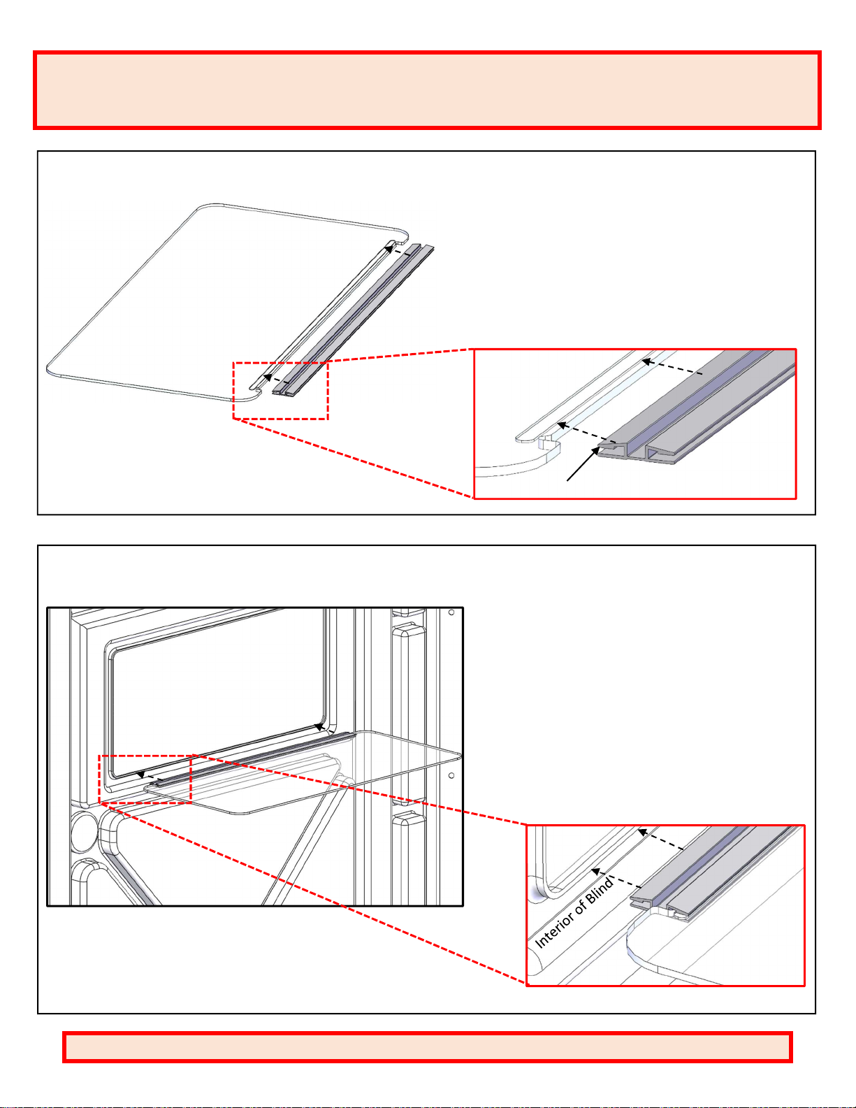
STEP
12
:
Attach (5
)
Windows [INS-COMMON TAB PLEXIGLASS]
to (5) Window Hinges [INS-COMMON LIVING HINGE]. Groove in
Window must snap into place on tab of Window Hinge. If
installed correctly and fully, a small snapping noise can be heard.
Tab o
n Hinge
NOTE
:
Window Hinges may be loose in the box OR
connected to the wall/door panels.
STEP
13
:
Attach (5
)
assembled Window/Hinges to the
Sidewalls and Door panel. Install from the interior of
the blind, and keep the Tab on the Hinge and the
Groove on the Window facing UP. Press fully over
edge of window cut out. If installed correctly and fully,
a small snapping noise can be heard.
NOTE: Window is designed to fold open completely. If
Hinge binds on itself during opening or closing it is
installed incorrectly.
Detailed View
Groove and TAB
facing UP
Table of contents
Other TERRAIN Tent manuals


Popular Tent manuals by other brands

NRS Relief
NRS Relief HuggyPRO 72 m2 Assembly manual

NORTHPOLE
NORTHPOLE 37-91-51 owner's manual

Coleman
Coleman RANGEVIEW 5 9230-110 user manual

BELL TENT VILLAGE
BELL TENT VILLAGE BTV instruction manual

Royal
Royal 302630 quick start guide

Forever Redwood
Forever Redwood ILLUMINATI PORCH PAVILION Assembly instructions


