TERRATEST 5000 BLU User manual

Made in Germany
‘TERRATEST 4000 USB’
‘TERRATEST 5000 BLU’
Instruction
Manual


Instruction Manual
Light Weight Deflectometer
for the dynamic plate load test
‘TERRATEST 4000 USB’
‘TERRATEST 5000 BLU’
with integrated GPS system and Google®Maps interface
Corresponding to
international standard:
‘ASTM E2835-11 Standard Test Method for Measuring
Deflection using a Portable Impulse Plate Load Test Device’
German standard:
‘Technical Test Code for Soil and Rock Mechanics
in Road Constructions TP BF-StB Part B 8.3’
Austrian standard:
‘RVS 08.03.04
Compaction Tests by means of the Dynamic Plate Load Test’
as well as
‘RIL 836 - Deutsche Bahn AG for Track Construction’
TERRATEST GmbH ensures constant improvement and development of its products and hence reserves the right
to make changes to its products at any time, and without prior notice.
This instruction manual is protected by copyright. It is explicitly forbidden to copy, change, publish or translate
this document or extracts thereof without prior written approval by TERRATEST GmbH.
® October 2014 TERRATEST GmbH. All rights reserved.
TERRATEST GmbH
Friedrich-Wolf-Strasse 13 · 16515 Oranienburg
GERMANY
Phone.: +49 3301 700 700 · Fax: + 49 3301 55 44 0

4
1. Documentation . . . . . . . . . . . . . . . . . . . . . . . . . . . . . . . . . . . . . . . . . . . . . . . .6
1.1 Notes on the Documentation . . . . . . . . . . . . . . . . . . . . . . . . . . . . . . .6
1.2 General Safety Information . . . . . . . . . . . . . . . . . . . . . . . . . . . . . . . . .7
1.3 Safety Precautions during Power Supply . . . . . . . . . . . . . . . . . . . . . . . .8
1.3.1 Power Supply . . . . . . . . . . . . . . . . . . . . . . . . . . . . . . . . . . . .8
1.3.2 Mains Power Supply . . . . . . . . . . . . . . . . . . . . . . . . . . . . . . .8
1.3.3 Car Charger Lead . . . . . . . . . . . . . . . . . . . . . . . . . . . . . . . . .8
1.3.4 Measuring Cable . . . . . . . . . . . . . . . . . . . . . . . . . . . . . . . . . .8
1.4 Safety Precautions during Operation . . . . . . . . . . . . . . . . . . . . . . . . . .9
1.5 Packaging . . . . . . . . . . . . . . . . . . . . . . . . . . . . . . . . . . . . . . . . . . . . .10
2. Contents of Delivery . . . . . . . . . . . . . . . . . . . . . . . . . . . . . . . . . . . . . . . . . . .12
2.1 Basic Package ‘TERRATEST 4000 USB’ . . . . . . . . . . . . . . . . . . . . . . . .12
2.2 Optional Equipment ‘TERRATEST 4000 USB’ . . . . . . . . . . . . . . . . . . .12
2.3 Basic Package ‘TERRATEST 5000 BLU’ . . . . . . . . . . . . . . . . . . . . . . . .13
2.4 Optional Equipment ‘TERRATEST 5000 BLU’ . . . . . . . . . . . . . . . . . . .13
2.5 General View – ‘TERRATEST 4000 USB’ . . . . . . . . . . . . . . . . . . . . . . .14
2.6 Top View of Control Panel, Testing Computer – ‘TERRATEST 4000 USB’ .15
2.7 General View – ‘TERRATEST 5000 BLU’ . . . . . . . . . . . . . . . . . . . . . . .16
2.8 Top View of Control Panel, Testing Computer – ‘TERRATEST 5000 BLU’ .17
3. Technical Specifications . . . . . . . . . . . . . . . . . . . . . . . . . . . . . . . . . . . . . . . . .18
3.1 Device Designation . . . . . . . . . . . . . . . . . . . . . . . . . . . . . . . . . . . . .18
3.2 Serial Number . . . . . . . . . . . . . . . . . . . . . . . . . . . . . . . . . . . . . . . . .18
3.3 Load Plate . . . . . . . . . . . . . . . . . . . . . . . . . . . . . . . . . . . . . . . . . . . .19
3.4 Mechanical Loading Device . . . . . . . . . . . . . . . . . . . . . . . . . . . . . . .19
3.5 Testing Computer . . . . . . . . . . . . . . . . . . . . . . . . . . . . . . . . . . . . . . .19
3.6 Environmental Conditions . . . . . . . . . . . . . . . . . . . . . . . . . . . . . . . . .19
3.7 Power Supply . . . . . . . . . . . . . . . . . . . . . . . . . . . . . . . . . . . . . . . . . .20
3.8 Battery Performance . . . . . . . . . . . . . . . . . . . . . . . . . . . . . . . . . . . . .20
3.9 Charging of Testing Computer . . . . . . . . . . . . . . . . . . . . . . . . . . . . . .21
3.10 Charging of Bluetooth®Load Plate (‘TERRATEST 5000 BLU’ ONLY) . . .21
3.11 USB Cable Port . . . . . . . . . . . . . . . . . . . . . . . . . . . . . . . . . . . . . . . . .23
3.12 Measuring Cable . . . . . . . . . . . . . . . . . . . . . . . . . . . . . . . . . . . . . . .24
4. General Overview: Light Weight Deflectometer . . . . . . . . . . . . . . . . . . . . . . .26
4.1 Introduction . . . . . . . . . . . . . . . . . . . . . . . . . . . . . . . . . . . . . . . . . . .26
4.2 Innovations . . . . . . . . . . . . . . . . . . . . . . . . . . . . . . . . . . . . . . . . . . . .26
4.2.1 Mechanical Innovations . . . . . . . . . . . . . . . . . . . . . . . . . . . .26
4.2.2 Electronic Innovations . . . . . . . . . . . . . . . . . . . . . . . . . . . . .26
4.3 Dynamic Plate Load Test . . . . . . . . . . . . . . . . . . . . . . . . . . . . . . . . . .27
4.4 Area of Application . . . . . . . . . . . . . . . . . . . . . . . . . . . . . . . . . . . . . .27
4.5 Calibration . . . . . . . . . . . . . . . . . . . . . . . . . . . . . . . . . . . . . . . . . . . .28
4.6 12 Rules for Proper Use . . . . . . . . . . . . . . . . . . . . . . . . . . . . . . . . . .28
4.7 Proposal for the Correlation of
Static / Dynamic Plate Load Test . . . . . . . . . . . . . . . . . . . . . . . . . . . .29
4.8 Interpreting the Test Results . . . . . . . . . . . . . . . . . . . . . . . . . . . . . . . .29
4.9 Determining the Residual Compaction . . . . . . . . . . . . . . . . . . . . . . . .31
5. Test Execution ‘TERRATEST 4000 USB’ . . . . . . . . . . . . . . . . . . . . . . . . . . . . . .32
5.1 Preparing the Testing Point . . . . . . . . . . . . . . . . . . . . . . . . . . . . . . . .32
5.2 Test Execution / Data Input Function . . . . . . . . . . . . . . . . . . . . . . . . .32
5.3 Printing the Test Protocol . . . . . . . . . . . . . . . . . . . . . . . . . . . . . . . . . .36
5.4 Changing the Paper . . . . . . . . . . . . . . . . . . . . . . . . . . . . . . . . . . . . . .36
6. Test Execution ‘TERRATEST 5000 BLU’ . . . . . . . . . . . . . . . . . . . . . . . . . . . . . .38
6.1 Preparing the Testing Point . . . . . . . . . . . . . . . . . . . . . . . . . . . . . . . .38
6.2 Test Execution / Data Input Function . . . . . . . . . . . . . . . . . . . . . . . . .38
6.3 Connecting Bluetooth®Load Plate to Testing Computer
with the Measuring Cable . . . . . . . . . . . . . . . . . . . . . . . . . . . . . . . . .42
6.4 The ‘Magic Eye’ of the Bluetooth®Sensor Dome . . . . . . . . . . . . . . . . .42
6.5 Continuous Measuring Mode . . . . . . . . . . . . . . . . . . . . . . . . . . . . . .43
6.6 Printing the Test Protocol . . . . . . . . . . . . . . . . . . . . . . . . . . . . . . . . . .44
6.7 Changing the Paper . . . . . . . . . . . . . . . . . . . . . . . . . . . . . . . . . . . . . .44
Table of Contents

5
7. Menu Guidance . . . . . . . . . . . . . . . . . . . . . . . . . . . . . . . . . . . . . . . . . . . . . . .46
7.1 Menu ‘USB STICK’ . . . . . . . . . . . . . . . . . . . . . . . . . . . . . . . . . . . . .46
7.2 Subsequent Printing of Test Data . . . . . . . . . . . . . . . . . . . . . . . . . . . .47
7.3 Language Menu . . . . . . . . . . . . . . . . . . . . . . . . . . . . . . . . . . . . . . . .48
7.4 Menu GPS / TIME . . . . . . . . . . . . . . . . . . . . . . . . . . . . . . . . . . . . . . .49
7.4.1 GPS Reception . . . . . . . . . . . . . . . . . . . . . . . . . . . . . . . . . .49
7.4.2 Accuracy of GPS Reception . . . . . . . . . . . . . . . . . . . . . . . . .49
7.4.3 GPS ON / GPS OFF . . . . . . . . . . . . . . . . . . . . . . . . . . . . . .50
7.4.4 Summer Time Function . . . . . . . . . . . . . . . . . . . . . . . . . . . .50
7.4.5 Date and Time . . . . . . . . . . . . . . . . . . . . . . . . . . . . . . . . . .51
7.4.6 Manual Time . . . . . . . . . . . . . . . . . . . . . . . . . . . . . . . . . . . .51
7.4.7 Time Zones . . . . . . . . . . . . . . . . . . . . . . . . . . . . . . . . . . . . .52
7.4.8 Time Zone Set-up . . . . . . . . . . . . . . . . . . . . . . . . . . . . . . . .52
7.5 Internal Memory . . . . . . . . . . . . . . . . . . . . . . . . . . . . . . . . . . . . . . . .53
7.5.1 Printing from the Internal Memory . . . . . . . . . . . . . . . . . . . .53
7.5.2 Internal Memory to PC . . . . . . . . . . . . . . . . . . . . . . . . . . . .53
7.5.3 Internal Memory to External Media . . . . . . . . . . . . . . . . . . .54
7.54 Clear Internal Memory . . . . . . . . . . . . . . . . . . . . . . . . . . . .54
7.6 Service . . . . . . . . . . . . . . . . . . . . . . . . . . . . . . . . . . . . . . . . . . . . . . .55
7.6.1 Input Test . . . . . . . . . . . . . . . . . . . . . . . . . . . . . . . . . . . . . .55
7.6.2 Version . . . . . . . . . . . . . . . . . . . . . . . . . . . . . . . . . . . . . . . .55
7.6.3 Device Type 10 / 15 kg . . . . . . . . . . . . . . . . . . . . . . . . . . . .56
7.6.4 Display Contrast . . . . . . . . . . . . . . . . . . . . . . . . . . . . . . . . .56
7.6.5 Voice Output: Sound Service (‘TERRATEST 5000 BLU’ ONLY) . . .57
7.6.6 PC-Service and Calibration Mode . . . . . . . . . . . . . . . . . . . .57
7.6.7 BT Sensor Dome (‘TERRATEST 5000 BLU’ ONLY) . . . . . . . . .58
7.6.7.1 Stand-by Time . . . . . . . . . . . . . . . . . . . . . . . . . . . .58
7.6.7.2 Bluetooth Pairing . . . . . . . . . . . . . . . . . . . . . . . . . .58
8. ‘TERRATEST 2.0’ Software . . . . . . . . . . . . . . . . . . . . . . . . . . . . . . . . . . . . . . .59
8.1 Uninstalling the ‘TERRATEST 2.0’ Software . . . . . . . . . . . . . . . . . . . .59
8.2 (Re-) Installing the ‘TERRATEST 2.0’ Software . . . . . . . . . . . . . . . . . . .59
8.3 Using the ‘TERRATEST 2.0’ Software . . . . . . . . . . . . . . . . . . . . . . . . .61
8.3.1 Editing Logo and Company Data . . . . . . . . . . . . . . . . . . . . .62
8.3.2 Prepare USB Stick . . . . . . . . . . . . . . . . . . . . . . . . . . . . . . . .62
8.3.3 Reading the USB Stick . . . . . . . . . . . . . . . . . . . . . . . . . . . . .63
8.3.4 Reading the Chip Card . . . . . . . . . . . . . . . . . . . . . . . . . . . .64
8.3.5 Converting Old Test Data . . . . . . . . . . . . . . . . . . . . . . . . . . .65
8.3.6 Test Protocol of Individual Tests . . . . . . . . . . . . . . . . . . . . . .66
8.3.7 Test Data Loading . . . . . . . . . . . . . . . . . . . . . . . . . . . . . . . .69
8.3.8 Loading Data from Testing Computer . . . . . . . . . . . . . . . . . .70
8.3.9 Driver Installation for Testing Computer . . . . . . . . . . . . . . . .72
8.3.10 Edit / Save Protocol . . . . . . . . . . . . . . . . . . . . . . . . . . . . . . .74
8.3.11 Print Protocol / Export as PDF File . . . . . . . . . . . . . . . . . . . .77
8.3.12 Create Statistical Analysis . . . . . . . . . . . . . . . . . . . . . . . . . .78
8.3.13 Print Statistical Analysis / Export as PDF File . . . . . . . . . . . . .79
8.3.14 Google®Maps Statistics Overview . . . . . . . . . . . . . . . . . . . .79
8.3.15 Select language . . . . . . . . . . . . . . . . . . . . . . . . . . . . . . . . . .82
8.3.16 Search Function for Individual Tests . . . . . . . . . . . . . . . . . . .83
9. Warranty . . . . . . . . . . . . . . . . . . . . . . . . . . . . . . . . . . . . . . . . . . . . . . . . . . . .85
10. EC Declaration of Conformity . . . . . . . . . . . . . . . . . . . . . . . . . . . . . . . . . . . .88
11. Standards . . . . . . . . . . . . . . . . . . . . . . . . . . . . . . . . . . . . . . . . . . . . . . . . . . . .89
11.1 ZTV-E-StB 09 . . . . . . . . . . . . . . . . . . . . . . . . . . . . . . . . . . . . . . . . . .89
11.2 RIL 836 - Deutsche Bahn AG . . . . . . . . . . . . . . . . . . . . . . . . . . . . . . .90
11.3 RVS 08.03.04 . . . . . . . . . . . . . . . . . . . . . . . . . . . . . . . . . . . . . . . . . .91
12. Cable Layout . . . . . . . . . . . . . . . . . . . . . . . . . . . . . . . . . . . . . . . . . . . . . . . . .92

6
1. Documentation
1.1 Notes on the Documentation
Congratulations on your purchase of your Light Weight Deflectometer from the TERRATEST product family.
By selecting this innovative test instrument you have chosen a cutting-edge product featuring the latest
technology. To be able to make full use of all the advantages and possibilities that this high-tech product
offers, and to ensure the proper use of the device according to the manual, please take a little time to read
this documentation carefully before use. The chapters contain everything you need to know about the device
and give valuable tips and recommendations for the proper use of this product. Reading this documentation
carefully will ensure that you will always obtain precise test results, which will give you a clear indication as
to the bearing capacity of the soil.
Read the instruction manual carefully and operate the device in accordance with the instructions.
TERRATEST GmbH will not be liable for damages caused by failure to observe these instructions.
All details contained in this documentation are subject to change without prior notice. TERRATEST GmbH
gives no assurance as to the accuracy of this documentation, and specifically disclaims any implied
warranties of merchantability or fitness for a particular purpose.
TERRATEST GmbH cannot be held liable for errors contained in this documentation, or for accidental or
sequential damage in connection with the delivery, performance, or use of the material.
PLEASE OBSERVE THE INSTRUCTIONS OF THE GERMAN STANDARD
‘Technical Test Code for Soil and Rock Mechanics in Road Construction TP BF-StB Part B 8.3’.
Evaluate the test data strictly in accordance with ZTV-E, ZTV-A, RIL 836 and/or RVS 08.03.04.
We would like to point out explicitly that a reliable evaluation of the test data is only possible if a cor-
relation measurement with the static plate load test is performed for every dynamic test with the Light
Weight Deflectometer. At least three static plate load tests should be performed for a reliable calibration
(see p. 29/30).
7
1.2 General Safety Information
Please read and understand the following safety guidelines, before starting to use ‘TERRATEST 4000 USB’
/ ‘TERRATEST 5000 BLU’.
Useful information and instructions
ATTENTION
Indicates processes where incorrect execution could result in physical injury or material damage.
Please observe these warnings carefully to ensure a safe operation of the device.
ATTENTION
If the Light Weight Deflectometer is used in a manner not specified by these instructions, the protection
provided by this instrument may be impaired.
ATTENTION (Quotation from ZTV E-StB 09)
‘The deformation modulus Ev2 is to be assessed by the static plate load test, in accordance with
DIN 18134, and the dynamic deflection module Evd with the dynamic plate load test, in accordance
with TP BF-StB Part B 8.3.... The specifications of the building contract should state whether the static or
dynamic deflection modulus is to be established. If no such statement is to be found in the contract, the
static deformation modulus will need to be established.’
ATTENTION
The evaluation of the measured Evd value depends on the material and the subsoil being tested. It is
always necessary to determine correlation values of the static plate load test on a trial basis for the
pre-existing ground or the ground intended for backfilling. Homogeneous ground is a prerequisite for
properly correlating the two measuring methods. Accordingly, the water content of the soil must not vary
widely.
ATTENTION
According to German standard TP BF-StB Part B 8.3, Light Weight Deflectometers must be calibrated at
least once a year at a calibration institute accredited by the German Federal Road Research Institute
(Bundesanstalt für Straßenbau). Test results of a device that has not been calibrated or of a device with
an expired calibration date must not be used for evaluating the bearing capacity of soil or rock. Abide
by the mandatory calibration intervals.
CAUTION
Never place the testing computer or load plate of ‘TERRATEST 5000 BLU’ near any inflammable liquids
such as alcohol, thinner etc. There is a risk of fire if such flammable liquids make contact with the electric
components in the interior of the device.
CAUTION
Never place or charge the testing computer or load plate of ‘TERRATEST 5000 BLU’ in areas with excessive
humidity, high temperatures, direct sunlight, or close to open flames. Doing so carries the risk of fire or
electric shock.
CAUTION
Whenever the loading device is not placed on the metal ball of the sensor dome on the load plate, always
store it horizontally or on the magnetic plate, which may be purchased separately. The loading device could
fall over and cause injuries otherwise.
CAUTION
Before operating the Light Weight Deflectometer read the instruction manual carefully to ensure correct
set-up of the device. When no test is performed, keep the drop weight in its ‘rest’ position at the bottom
of the guide rod. The drop weight could fall down and cause injuries or damage otherwise.
8
1.3. Safety Precautions during Power Supply
CAUTION
Never place any heavy objects on the measuring or charging cables. Never twist or pull them, and take
care that they do not become knotted.
CAUTION
Ensure that the charging and measuring cables are fully inserted into their sockets. A poor connection can
lead to equipment damage. Use only the cables provided.
1.3.1. Power Supply
ATTENTION
Only batteries approved by the manufacturer (Panasonic LCR-6V 4.2 P) should be used for the testing
computer. Batteries should only be replaced and disposed of by qualified personnel. The plugs of the
cable, to which the battery will be connected, are colour-coded. The white wire with the red plug should
be connected to the positive (+) pole of the battery (+6 volts). The brown wire with the black plug should
be connected to the negative (-) pole of the battery. The cable contains a 2A/32V fuse.
Only the permanently-installed, long-lasting, rechargeable battery pack approved by the manufacturer
(type 8904 7.4 V/2.4 Ah) should be used in the Bluetooth®sensor dome (‘TERRATEST 5000 BLU’ ONLY).
This battery pack should only be replaced by the manufacturer.
ATTENTION
The assembly may be destroyed if the leads of the battery are interchanged, or a different type of fuse is
inserted.
No tests should be performed while charging the device.
1.3.2. Mains Power Supply
ATTENTION
Only power cables approved by the manufacturer (SA07-15US12R) may be used for the testing computer.
When using the power cable to charge the device, take care to do so only in dry, indoors locations. The
inner pole is the positive (+) pole.
Only power cables with LEMO-plugs approved by the manufacturer (SYS1308-1809-W2E) should be used
for charging the Bluetooth®transmission unit in the Bluetooth®sensor dome (‘TERRATEST 5000 BLU’
ONLY). When using the power cable to charge the device, take care to do so only in dry, indoors locations.
The inner pole is the positive (+) pole.
1.3.3. Car Charger Lead
ATTENTION
Only car chargers approved by the manufacturer may be used. Charging should only be done inside dry
rooms (the interior of the vehicle, for example). The inner pole is the positive (+) pole.
ATTENTION
Always hold the plug when disconnecting the charger cable. Wires may be damaged if the cables are
pulled directly.
1.3.4. Measuring Cable
ATTENTION
Only the original measuring cable / extension cable supplied by the manufacturer should be used. Cables
should not be disassembled or extended. Incorrect test results may occur otherwise.
9
1.4. Safety Precautions during Operation
ATTENTION
TERRATEST GmbH shall not be liable for any damage, consequential damage, or financial loss that occurs
as a result of improper use of the device and / or lack of professional knowledge when evaluating the test
data. It is essential to ensure that the calibration of the device is always up to date and that the device is
always operated in accordance with the instructions of this document as well as your local standard.
CAUTION
Use the Light Weight Deflectometer only outdoors. Never use it inside any enclosed area. Using the
device indoors carries the risk of damage to the building. Never use the device on paving stones, tiles,
cobblestones, floor boards, asphalt, cement, industrial flooring, or any other type of flooring; these may be
damaged by the impact of the dropping weight.
ATTENTION
Never disassemble or alter the Light Weight Deflectometer, the testing computer, or any other equipment
such as the charger cable etc.
ATTENTION
In case of unusual noise, smoke, smell, or excessive heat generation, switch off the device immediately
and contact TERRATEST customer support.
ATTENTION
Do not expose the testing computer or load plate of ‘TERRATEST 5000 BL’’ to direct rainfall.
If it rains, cover and protect testing computer and load plate of ‘TERRATEST 5000 BLU’.
ATTENTION
Protect the testing computer and load plate of ‘TERRATEST 5000 BLU’ from water, liquids, and any
flammable substances. There is a risk of fire if flammable liquids enter the device and make contact with
the electric components.
CAUTION
Clean surfaces with solvent-free cleaning agents only. Gently wipe surfaces with a soft, dry cloth. If dirt
remains, use a cloth moistened with water, well-wrung, and then wipe with a soft, dry cloth to absorb any
remaining moisture. Never use flammable substances such as alcohol, benzine or thinner for cleaning.
There is a risk of fire if flammable liquids enter the device and make contact with the electric components,
or if the cables get damaged. Thus, always take care when connecting or disconnecting the cables.
ATTENTION
Let go of the lid of the testing computer only after it has been fully closed / opened. If the lid falls down it
may cause injury to your hands. No objects should be placed on the inspection window.
CAUTION
When placing the load plate on the test ground, and for removing it, kneel down on one knee and grab
the load plate with both hands on the handles. Do not let the load plate fall down; doing so may injure
your feet, or damage the device.
CAUTION
Always transport the loading device with the drop weight locked; failure to do so carries the risk of
personnel injury or damage to the device. Keep the drop weight locked in its ‘rest’ position at the bottom
of the loading device and unlock it only immediately prior to conducting a test. Failure to observe these
points may cause the device to be damaged, and there may be a high risk of personnel injury. When
latched at the top of the loading device, take care to release the drop weight only immediately prior to
conducting a test. Pull up the drop weight, latch it at the top, and release it immediately afterwards.
CAUTION
The transportation lock should be unlocked only immediately prior to conducting a test. Uncontrolled
movements of the weight may cause injury, or damage to the device or its surroundings. Regularly check
10
that the transportation lock of the Light Weight Deflectometer is functioning properly. If you notice signs of
wear, stop using the device immediately. Send the device back to TERRATEST for the transportation lock to
be repaired or replaced.
Never transport the loading device, or let it stand around, while the drop weight is latched at the top!
ATTENTION
When conducting a test, only the operator should come close to the device. Release the drop weight only
when no one else is beneath or near the Light Weight Deflectometer.
CAUTION
Hearing protectors must be worn when operating the Light Weight Deflectometer, since the noise level
may rise over 85 dB. ATTENTION: Operating the device without hearing protection may result in
permanent hearing impairment.
ATTENTION
If the device will not be used for a longer period of time, ensure that all cables are disconnected.
Before transporting the device, ensure that all cables are disconnected.
Before moving the device around the construction site, ensure that all cables are disconnected.
Damaged cables may cause fire.
No tests should be performed while the apparatus is on charge; this can distort test results!
CAUTION
Never insert the enclosed CD-ROM into a normal CD player; doing so will generate a loud noise.
According to the Waste Electrical and Electronic Equipment Directive (2002/95/EG) the battery,
electronics, and especially the electronics of the load plate may not be disposed of with your domestic
waste. Comply with your local regulations. In some countries you are required by law to dispose of these
products only at the collection points provided. In some countries manufacturers of similar electronic
equipment are obliged by law to take back electronic waste. Due to potentially hazardous substances,
often contained in electronic waste, incorrect handling of such waste may have negative impacts on the
environment and human health. By disposing of electronic parts in an appropriate way you also
contribute to an effective use of natural resources.
For more information about collection points for electronic waste please contact your city council, your
public waste management authorities, or your garbage disposal service.
TERRATEST GmbH will take back electronic waste free of charge, and dispose of it in a safe and
environmentally appropriate manner.
1.5 Packaging
We strongly recommend that you keep the original packaging of the device for transport at a later date
(e.g. when sending the device in for calibration). Upon delivery, inspect the device immediately. Make
sure that the goods are undamaged and complete. Check in particular that there is no visible external
damage to the packaging. If the device or any other item included in the delivery is damaged, immediately
record the type of damage and notify the carrier that you may seek compensation. Please also advise
TERRATEST GmbH of the damage and the name of the carrier, so that we can also get in contact with the
transport company.


12
2. Contents of Delivery
2.1 Basic Package ‘TERRATEST 4000 USB’
Light Weight Deflectometer 10 kg
corresponding to German standard TP BF-StB Part B 8.3
‘TERRATEST 4000 USB’ with integrated GPS system and Google®Maps interface
consisting of:
■10 kg loading device with ergonomic weight-catching grip
■Load plate 300 mm
■Testing computer with GPS system,
internal plausibility check and test data comparison,
internal memory for up to 2000 tests
backlit graphic display for presentation of settlement curves during test,
thermal printer with paper roll, port for USB flash drive,
integrated rechargeable battery, external control button,
large inspection window enabling operation under adverse weather conditions
■Connection cable with jack plug for testing computer / load plate
■User-friendly ‘TERRATEST 2.0’ software with statistical analysis
in accordance with German standard TP BF-StB Part B 8.3
■USB stick for test data storage
■Power cable 100 ... 240 V~ / 12 V 1.25 A
■Car charger lead 12 V/DC
■Detailed instruction manual
■Calibration certificate according to German standard
‘TP BF-StB Part B 8.3 for Soil and Rock Mechanics in Road Constructions’
2.2 Optional Equipment ‘TERRATEST 4000 USB’
■Loading device with 15 kg drop weight and strengthened spring assembly, calibration certificate
■‘CARRELLO’, the mobile testing system, for testing without carrying
■Transport box ‘MILANO’, made of plywood and an aluminium profile,
with integrated handles and wheels
■Transport box ‘ROMA’, made of plywood and an aluminium profile, with integrated handles and
wheels, for combined transport of 10 kg basic package and 15 kg loading device
■Magnetic plate ‘TRETMINE’, for the convenient placement of the loading device on the ground
■Extension cable, load plate / testing computer, for extended range as well as tests in areas that are
difficult to access such as trenches etc.
■Paper rolls for thermal printer

13
2.3 Basic Package ‘TERRATEST 5000 BLU’
Light Weight Deflectometer 10 kg
corresponding to German standard TP BF-StB Part B 8.3
‘TERRATEST 5000 BLU’ with integrated GPS system and Google®Maps interface
consisting of:
■10 kg loading device with ergonomic weight-catching grip
■Load plate 300 mm with Bluetooth®transmission electronics in the sensor dome and integrated
rechargeable battery pack type 8904 7.4V/2.4Ah
■Testing computer with GPS system,
internal plausibility check and test data comparison,
‘continuous measuring mode’, voice output,
internal memory for up to 2000 tests,
backlit graphic display for presentation of settlement curves during test,
thermal printer with paper roll, port for USB flash drive,
integrated rechargeable battery, external control button,
large inspection window enabling operation under adverse weather conditions
■Connection cable with high-quality push-pull connectors from LEMO for testing computer / load plate
■User-friendly software ‘TERRATEST 2.0’ with statistical analysis
in accordance with German standard TP BF-StB Part B 8.3
■USB stick for test data storage
■Power cable 100 ... 240 V~ / 12 V 1.25 A and
power cable 100 ... 240 V~ / 9 V 2 A with plugs from LEMO
■Car charger lead 12 V/DC
■Detailed instruction manual
■Calibration certificate according to German standard
‘TP BF-StB Part B 8.3 for Soil and Rock Mechanics in Road Constructions’
2.4 Optional Equipment ‘TERRATEST 5000 USB’
■Loading device with 15 kg drop weight and strengthened spring assembly, calibration certificate
■‘CARRELLO’, the mobile testing system, for testing without carrying
■Transport box ‘MILANO’, made of plywood and an aluminium profile, with integrated handles and
wheels
■Transport box ‘ROMA’, made of plywood and an aluminium profile, with integrated handles and
wheels, for combined transport of 10 kg basic package and 15 kg loading device
■Magnetic plate ‘TRETMINE’, for convenient placement of the loading device on the ground
■Paper rolls for thermal printer
14
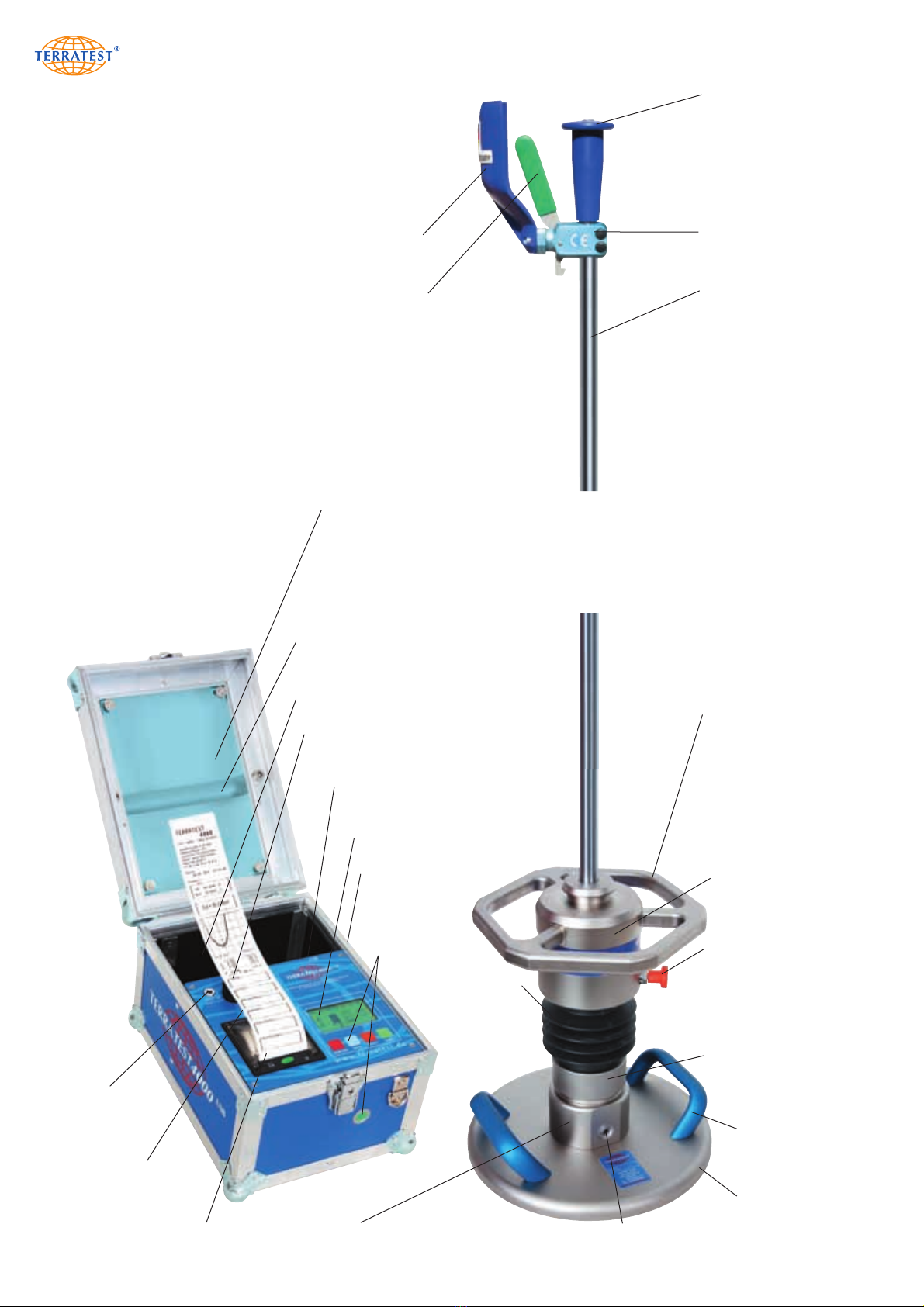
safety grip with
integrated spirit level
release mechanism
guide rod
weight-catching grip
GPS antenna
(not visible)
storage box
handle
transportation
lock
drop weight
bellows
(not visible:
spring element)
anti-tipper
handle
load plate
300 mm
socket
for sensor connection
socket for sensor
connection
(not visible)
sensor dome
(not visible: sensor)
thermal printer
USB stick port
(not visible)
2.5 General View – ‘TERRATEST 4000 USB’
electronic
testing computer
mechanical
loading device
load plate
control panel
graphic display
USB cable port
(not visible)
charging socket
12 V/220 V
inspection window
release lever
impact protector
15
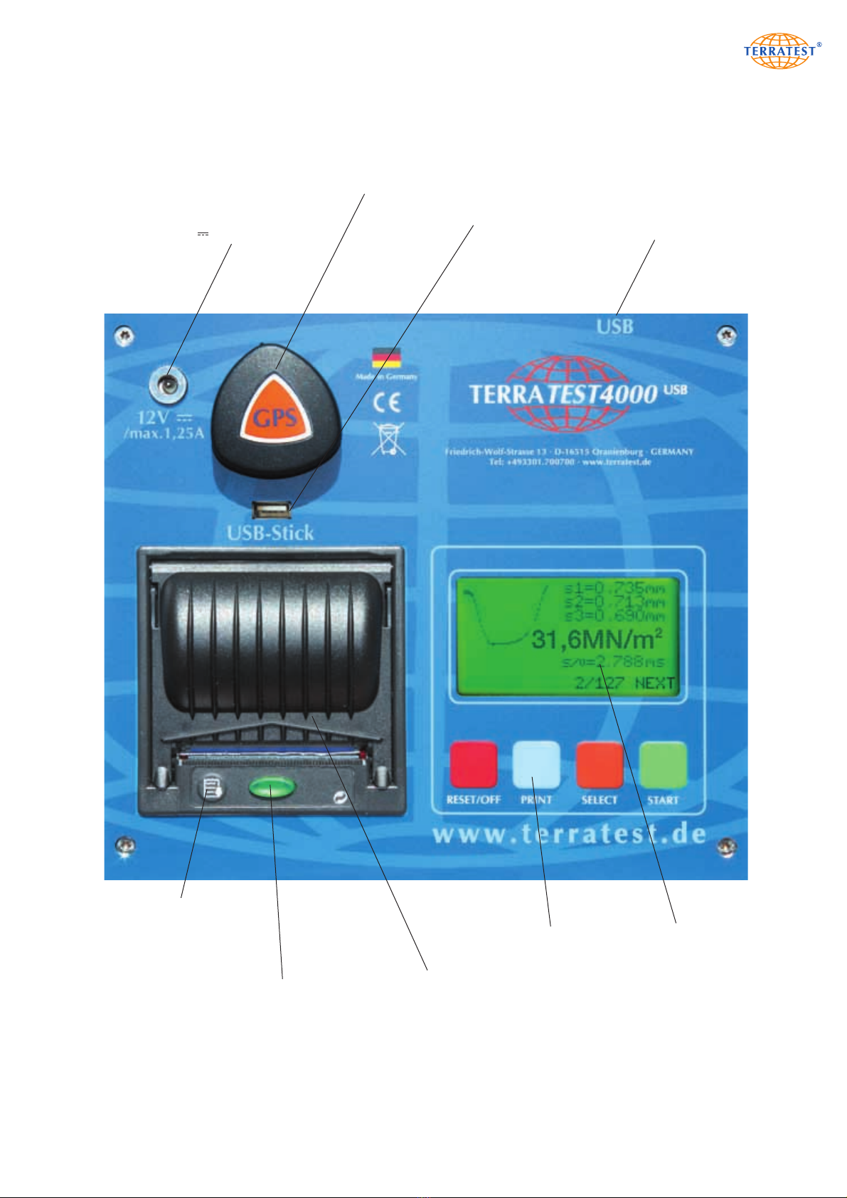
thermal printer
control lamp printer,
button for opening
the paper tray
button for
paper feed
GPS antenna
backlit
graphic display
control buttons
USB stick port USB cable port
(on the back panel)
2.6 Top View of Control Panel, Testing Computer – ‘TERRATEST 4000 USB’
charging socket
12V /max. 1.25A

16
safety grip with
integrated spirit level
release mechanism
guide rod
weight-catching grip
GPS antenna
(not visible)
storage box
handle
transportation
lock
drop weight
bellows
(not visible:
spring element)
anti-tipper
handleload plate
300 mm
sensor dome
(not visible: sensor)
‘the magic eye’
Bluetooth®transmitter
with control lamp
thermal printer
USB-Stick port
(not visible)
2.7 General View – ‘TERRATEST 5000 BLU’
electronic
testing computer
mechanical
loading device
load plate
control button
(not visible)
control panel
graphic display
USB cable port
charging socket
12 V/220 V
inspection window
release lever
impact protector
socket for sensor
connection / socket
for charging the
battery (not visible)
socket for sensor
connection
(not visible)
17
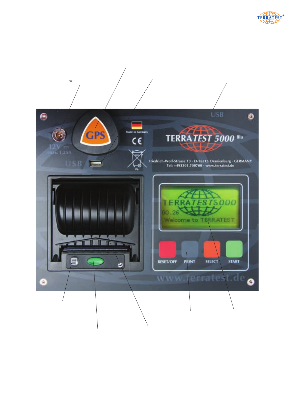
thermal printer
control lamp
printer,
button for opening
the paper tray
button for
paper feed
GPS antenna
backlit
graphic display
control buttons
USB-Stick port USB cable port
(on the back panel)
2.8 Top View of Control Panel, Testing Computer – ‘TERRATEST 5000 BLU’
charging socket
12V /max. 1.25A
18
3. Technical Specifications
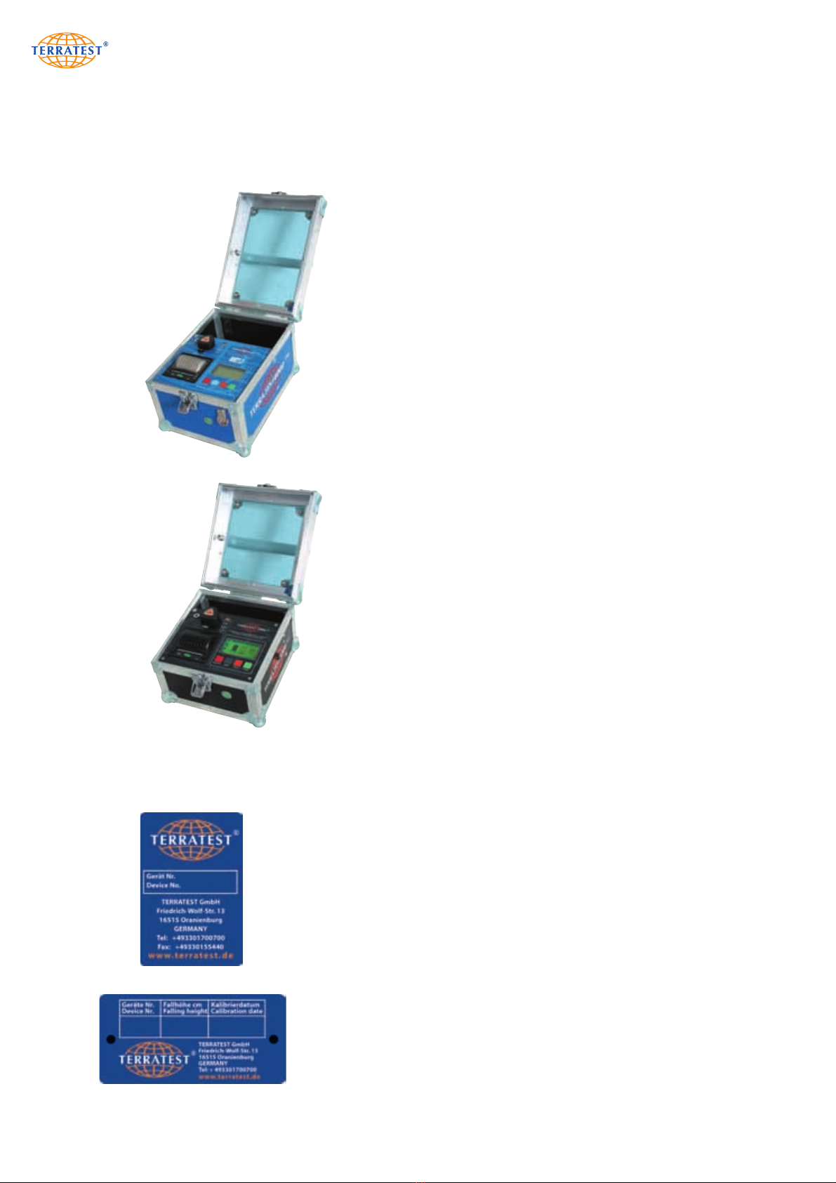
3.1 Device Designation:
‘TERRATEST 4000 USB’
with box for testing computer ‘Robusta’
(box made of air chamber panels
and aluminium profiles,
external button on the front face)
‘TERRATEST 5000 BLU’
with box for testing computer ‘Robusta’
(box made of air chamber panels
and aluminium profiles,
external button on the front face)
4193 71,5 10/14
4193
3.2 Serial Number:
Load plate, loading device and testing computer form a single unit and
have been attuned to one another during calibration of the device. These
three components may only be used in conjunction with each other and
may not be interchanged with the components of other devices.
Accordingly, the single components are identified with particular serial
numbers. These serial numbers are identical and located on metal tags,
which are attached to each component. Each serial number consists of
a four-digit number.
The serial number is located:
On the load plate, directly between the handles.
Inside the testing computer, on the partition panel in the storage box.
On the drop weight of the loading device. Additionally, drop height as
well as month and year of last calibration are noted here.

19
3.3 Load Plate:
Weight of load plate,
including sensor dome and handles 15 kg
Diameter of load plate 300 mm
Thickness of load plate 20 mm
Power supply Bluetooth®transmitter long-lasting, rechargeable
Bluetooth®sensor dome (‘TERRATEST 5000 BLU’ ONLY) battery pack type 8904 7.4V/2.4Ah
3.4 Mechanical Loading Device: 10 kg 15 kg
Impact force 7.07 kN ± 1% 10.605 kN ± 1%
Impact duration 17 ms ± 1.5 ms 17 ms ± 1.5 ms
Weight of drop weight 10 kg 15 kg
Weight of guide rod 5 kg 5.5 kg
Length of guide rod 1140 mm 1140 mm
Total height of device, including load plate 1230 mm 1230 mm
Sound power level 95 dB(A) 95 dB(A)
Sound pressure level 84 dB(A) 84 dB(A)
3.5 Testing Computer
Weight without accessories 4.1 kg
Dimensions length = 240 mm
width = 230 mm
height = 230 mm
Measurement range (settlement) 15-70 MN/m270-120 MN/m2
Power supply long-lasting, rechargeable 6 Volt
PANASONIC-Super-Life lead acid battery
Automatic switch-off after three minutes
Radio clock, date display satellite-based, can be configured manually
Precision GPS receiver less than 20 meters
Maximum voltage variation +/- 10%
Bluetooth®transmitter / receiver Type RN-41/RN41-N Class 1
(‘TERRATEST 5000 BLU’ ONLY) Certifications FCC, ICS, CE, RoHS
Frequency range 2.402 ˜2.480 MHz
3.6 Environmental Conditions
Charge the device only in dry, indoors locations.
Protection class IP53
Do not expose the testing computer to direct rain.
If it rains, cover and protect the testing computer.
Do not expose Bluetooth®load plate (‘TERRATEST 5000 BLU’ ONLY) to direct rain.
If it rains, cover and protect Bluetooth®load plate (‘TERRATEST 5000 BLU’ ONLY).
Temperature range 0 - 40 °C
Maximum height for use above sea level 3,000 metres
Maximum relative humidity for use < 80%, dew must be avoided

20
3.7 Power Supply
Power consumption while on battery
normally 6V DC/0.5A (when backlight is on)
normally 6V DC/0.4A (when backlight is off)
3.8 Battery Performance
Battery 6V type Panasonic LCR-6V 4.2P (which may be replaced only by Technical Support Service)
Charging time approx. 4-5h, depending on ambient temperature
Fuse in battery cable: blade fuse ATO 2A/32V (31.75x6.35)
A long-lasting, rechargeable 6 Volt, 4.5 Ah built-in battery is located in the testing computer.
The device may be charged via either the supplied power cable or a 12 Volt car battery. The charging socket
‘12V /max 1.25A’ on the control panel, next to the GPS antenna, must be used for this. Both car
charger and power cable are included with the contents of delivery (basic package).
A long-lasting, rechargeable, built-in battery pack type 8904 7.4 V/2.4 Ah is located in the sensor dome
(‘TERRATEST 5000 BLU’ ONLY). It should be charged with the supplied power cable 9V DC/2A with plugs
from LEMO.
The battery charge of the testing computer will be shown on the display ‘STATUS REQUEST’ upon swit-
ching on the device. Fully charged, the battery holds 6.9 volts. Approximately 300 tests can be performed
with a new, fully charged battery. However, the battery performance also depends largely on density of
air pressure, ambient temperature, battery lifetime, and other criteria. The device switches off automatically
three minutes after last use (automatic switch-off). Shortly before total discharge of the battery, the testing
computer also turns off automatically to avoid deep discharge. It can only be activated again after
recharging.
The battery charge of the Bluetooth®transmitter in the sensor dome of the Bluetooth®load plate
(‘TERRATEST 5000 BLU’ ONLY) will be shown on the display ‘STATUS REQUEST’ upon switching on the
device. Fully charged, the battery holds 7.4 volts (= 100%). Approximately 300 tests can be performed
with a new, fully charged battery. However, the battery performance also depends largely on density of
air pressure, ambient temperature, battery lifetime, and other criteria. The device switches off automatically
three minutes after last use (automatic switch-off). Shortly before total discharge of the battery, the testing
computer also turns off automatically to avoid deep discharge. It can only be activated again after
recharging.
The battery should be replaced only by the manufacturer. Never attempt to dismantle the battery. Lead is
a highly toxic heavy metal. Please comply with the regulations regarding transport and disposal of lead
batteries. Do not dispose of batteries by burning them. Batteries must be kept out of reach of children.
According to the Waste Electrical and Electronic Equipment Directive (2002/95/EG) the battery,
electronics, and especially the electronics of the load plate may not be disposed of with your domestic
waste. Comply with your local regulations. In some countries you are required by law to dispose of these
products only at the collection points provided. In some countries manufacturers of similar electronic
equipment are obliged by law to take back electronic waste. Due to potentially hazardous substances,
often contained in electronic waste, incorrect handling of such waste may have negative impacts on the
environment and human health. By disposing of electronic parts in an appropriate way you also
contribute to an effective use of natural resources. For more information about collection points for
electronic waste please contact your city council, your public waste management authorities or your
garbage disposal service. TERRATEST GmbH will take back electronic waste free of charge, and dispose
of it in a safe and environmentally appropriate manner.
This manual suits for next models
1
Table of contents
Other TERRATEST Measuring Instrument manuals


