TERRY 1100W TSL1 User manual

1100W TSL1 Platform Lift
Original instructions


CONTENTS
Introduction 4
Description 4
General Do’s and Don’ts 6
Controls 7
Operating the Lift 8
Emergency procedures 9
Maintenance & Servicing 10
Fault finding 11
Safety feature checks 12
Service history record 13
Declaration of conformity 14
Lift specification 15
3

INTRODUCTION
Thank you for choosing the Terry 1100W TSL1 lift, designed and
manufactured in the U.K. using the latest technology from Terry
Group Ltd. We want you to get the most out of your 1100W TSL1
Lift and to help in this aim, we have produced this small booklet
on operation and maintenance of the equipment which we trust
you will find helpful.
It is hoped that any queries you may have during day to day
operation will be answered in the text but if you do have any
problems our technical help service is only a phone call away.
We hope that our product gives you many years of reliable
service.
Peter Morrey
Managing Director
DESCRIPTION
The Terry 1100W TSL1 Lift is designed to transport a single
person in a wheelchair between two floor levels up to 1 metre
apart. To provide the lifting force the lift uses a hydraulic cylinder
under the platform, fed via a hose from a pump unit mounted
under the power pack cover on the platform. Principal features of
the design are its low closed height and silent smooth operation.
The low closed height eliminates the need for a pit.
Control stations are provided on the platform and at the upper
and/or lower levels depending on requirements. Aremote control
enabler option is also available to limit the use of the lift to
authorised users only.
4
It is most important that before operating the lift you read these
instructions fully and are familiar with the controls and operating
procedure.
Our policy is one of continous product development and the
Company reserves the right to change specification without
notice.
If a change of use of the lift is required, this should be discussed
with the manufacturer/supplier as certain alterations may be
needed.
Examples of changes of use are:
a) change of type, size and/or weight of wheelchair;
b) change of user disability;
c) change of user;
d) removal of the homelift and reinstallation at another site;
e) change of duty cycle.
All changes of use should entail a review of the installation.
5
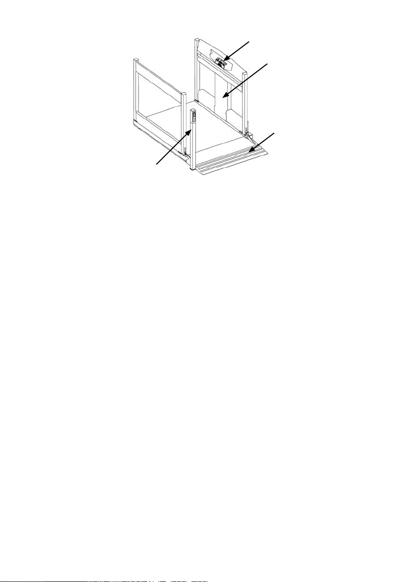
Control Post
Platform controls
Power pack
Ground ramp

GENERAL DO’S AND DON’TS
• Always leave the power supply to the lift switched on, even
when you go away. The lift control circuits are fed by a battery,
which must be kept constantly charging.
• Never allow children to play on or around the lift.
• Ensure that the area around the lift is kept clear from debris
(e.g. litter and leaves).
• Do not exceed the maximum lifting capacity of 385 kg.
• Always treat your lift with the respect that should be shown to
electrical and mechanical equipment.
WARNING! As recommended by the Medicines and Healthcare
products Regulatory Agency (MHRA), great care should be
exercised whilst manoeuvring on and off the platform ramp, to
avoid the risk of tipping over rearwards. Information can be found
at www.mhra.gov.uk
6

CONTROLS
Location
• Lower level control switch(standard installation)-mounted on
control post.
Or
• Lower level control switch (pit installation / side entry)
mounted on the building structure at the lower level.
• Platform control switch-mounted on lift the car control panel.
• Upper level control switch (no upper level gate) mounted on
the building structure at the upper level.
Or
• Upper level control switch (upper level gate) integral with the
gate frame.
Function
• All controls are of the “hold to run” type. Maintain pressure on
the switch until the lift reaches the upper or lower level. Press
one side of the switch to go up, press the other side of the
switch to go down.
• A key switch is located on the car control panel to isolate the
lift.
• An emergency stop button is located on the car control panel
to stop the lift in the case of an emergency.
• If the lift has been supplied with a remote control lift enabler
unit the lift will remain disabled until key fob is pressed.
Pressing the key fob will allow the lift to be operated by the
up/down control in the normal way. 3 minutes after pressing
the key fob the lift will automatically revert back to its disabled
mode preventing further use. The lift can then only be
reactivated for use by repressing the key fob.
7

OPERATING THE LIFT
If the radio control enabler option is fitted press the key fob to
activate the control stations.
The lift can be called by maintaining pressure on the call button
and waiting for it to stop at the appropriate level. Move on to the
platform and apply the wheelchair brakes. Press and maintain
pressure on the control button to operate the lift until it stops at
the required level.
If necessary, the lift can be stopped at any time by releasing the
control button.
The underside of the lift is fitted with a platform safety device
which automatically stops the lift if an obstruction is present
beneath the platform. Once the obstruction has been removed
the lift will continue to operate as normal.
We recommend that the lift is kept at the lower level when
not in use.
8

9
EMERGENCY PROCEDURES
a) Isolation of the lift is achieved by switching the key switch on the car
control panel or by switching off the isolator switch on the charger pack
located indoors.
b) In the unlikely event that the lift stops part-way through its travel and
will not restart, it can be lowered manually. First push the stop switch
down (1) then remove one posi-drive screw from the cover plate below
the car control panel and rotate the cover (2). Then push the lever to
the left (3) to lower the lift.
Please Note: If the platform is at the upper level and will not lower
follow emergency procedure above.
Be aware that the platform safety device does not function when
manually lowering the lift. Ensure that people are away from the
platform and that there are no obstructions.
c) The Isolator switch on the charger pack located indoors, should be
switched on at all times.
NOTE: Acompetent person will need to be called to restore the safety
functions of the lift before re-use.
12
3

MAINTENANCE & SERVICING
Provided the operating instructions are observed the lift will give
many years of trouble free service. It is designed for outdoor use
(but not for coastal applications).
Dependent on frequency of use, this lifting platform should
be serviced at least every 6 months. This service should be
conducted by competent persons trained in the service and
repair of the product.
If a lifting platform is to be installed in an adverse environment,
the specifier and supplier shall determine the measures needed
to ensure that safe operations are achieved including more
regular service intervals.
Note: Adverse environments are those that could affect safe
operation. Examples include; the effects of humidity, atmospheric
pollution, solar radiation, swimming pool environs (this product
is not suitable for use in chlorinated environments), extreme
temperatures, etc.
If in any doubt about the operation of the lift please contact the
installation company for advice.
10

FAULT FINDING
The table below should help solve any problems, which may be
stopping your lift from operating correctly. If, however, your lift
still does not operate correctly after referring to this table please
do not hesitate to call the number on the back of this booklet for
further advice.
Lift
Position Problem Cause Remedy
Lower level Lift will not
operate
Charger isolation
switch disabling
lift
Remote control
enabler(if fitted)
not activated.
Ensure charger
isolation switch
is on.
Activate remote
control enabler
with key fob.
Lift rises short
distance then
stops Obstruction on
ramp
Remove
obstruction on
ramp
Upper level Lift will not
operate
Charger isolation
switch disabling
lift.
Remote control
enabler(if fitted)
not activated
Ensure charger
isolation switch
is on.
Activate remote
control enabler
with key fob
Upper level
gate not closed
properly (where
fitted)
Ensure gate is
fully closed
Platform safe
edge obstructed Remove
obstruction
below the lift
Lift operates but
stops before the
lower level
Platform safe
edge obstructed Remove
obstruction
below the lift
11

SAFETY FEATURE CHECKS
As a precautionary measure it is advised that you check the
safety features built into the lift on a weekly basis. Carry out the
ckecks as discribed below: -
• Platform safe edge - With the lift at the upper level call the lift
down and once it is moving obstruct the platform safe edge,
the lift should stop.
• Folding ramp upper safe edge - With the lift at lower level
obstruct the upper surface of the ramp and send the lift up,
the lift should stop within 300mm of travel.
• Upper level gate - With the lift at the upper level open the
upper level gate and attempt to call the lift down from the
lower level. The lift should remain stationary.
All of these tests should be carried out with the lift
unoccupied.
If any of these tests fail, the lift MUST NOT be used and advice
sought by calling the number on the back of this booklet
12

SERVICE HISTORY RECORD
An entry should be added to the following table every time the lift
is serviced.
Date Engineer Company Comments
13

14
DECLARATION OF CONFORMITY
Lift Type: 1100W TSL1
This lift was manufactured by TERRY GROUP Ltd., who declare
that this lift fulfils all the relevant provisions of the following
Directives:
2004/108/EEC EMC Specifications
2006/42/EC Machinery Directive
This lift also fulfils all the relevant provisions of the following
Standards:
BSEN 12015:2004 Electromagnetic Compatibility. Product family
standard lifts, escalators and moving walks.
Emission.
BSEN 12016:2004
+A1:2008 Electromagnetic Compatibility. Product family
standard lifts, escalators and moving walks.
Immunity.
BS6440:2011 Powered lifting platforms for use by disabled persons
Person authorised to compile Technical File:
Greg Gnyp, Terry Group Ltd., Longridge Trading Estate,
Knutsford, Cheshire, WA16 8PR
This declaration was completed at Terry Group Ltd., Longridge
Trading Estate, Knutsford, Cheshire, WA16 8PR, in September
2011.
This compliance is only valid if the installation test Certificate
has been completed and signed by a competent lift engineer
which confirms that it has been installed to the latest installation
instructions.
TERRY GROUP Ltd.
P.Morrey (Managing Director)

LIFT SPECIFICATION
Address of manufacturer:
Terry Group Ltd.
Unit 1 Longridge Trading Estate
Knutsford, Cheshire, England
WA16 8PR
Lift serial No. Year of manufacture
Maximum load 385Kg
Maximum travel 1 metre
Power supply 240V AC ~ 50/60 Hz
Control voltage 24V DC
Hydraulic pump power
consumption 1200W maximum
Hydraulic oil grade T22
Standards Designed and manufactured to
BS6440
Service interval Maximum of 12 months between
services being reduced according
to usage and application.
Our policy is one of continuous product development and the
Company reserves the right to change specification without
notice.
15

This 1100 W TSL1 has been supplied by:
10250c
Table of contents
Other TERRY Lifting System manuals


Popular Lifting System manuals by other brands


Zepro
Zepro ZHD 1500 Service instruction

Coffing Hoists
Coffing Hoists LHH-1/2B Operating, maintenance and parts manual

Grainger
Grainger 12R539 Operating instructions and parts manual

Prism Medical
Prism Medical P440 owner's manual

TruckCraft
TruckCraft TC-515 owner's manual

Still
Still LiftRunner B frames Original instructions


