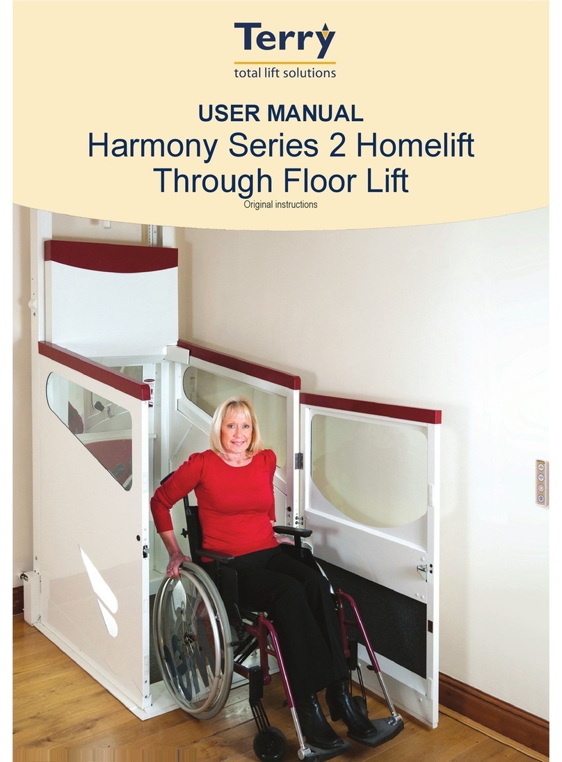
TERRY HARMONY 2 Series User manual

HARMONY Series 2
HOMELIFT
by Terry Group Ltd
Document Number: XH00200
Issue: D
Date: 23/01/12
This installation manual is to be left on site behind a cover panel.
The test certificate, once filled in, must be returned to office.
Installation Instructions
ORIGINAL INSTRUCTIONS

Harmony Series 2 Homelift - XH00200 Issue: D Page 2 of 106
Contents
Safe Handling / Lifting............................................................................................................4
Weights of Main Component..................................................................................................4
Working Under the Lift – ALWAYS FIT SAFETY SCOTCH...................................................5
Safe Working Environment....................................................................................................7
Safe Working Environment....................................................................................................9
Glossary of Terms................................................................................................................11
Site Preparation...................................................................................................................12
Wheelchair Aperture Details ................................................................................................13
Aperture Liner......................................................................................................................14
Aperture Trim Installation – Stage 1.....................................................................................16
Aperture Trim Installation – Stage 2.....................................................................................17
Harmony Lift Loading Diagram ............................................................................................18
Electrical Requirements.......................................................................................................19
Mounting of Power Pack & Wiring........................................................................................19
Lower Guide Installation Procedure.....................................................................................20
Preparing for Sling Installation.............................................................................................21
Intermediate Guide Installation – Long Sling ONLY.............................................................22
Middle & Lower Control Tube/Tray Installation ....................................................................23
Cover Aperture – Trapdoor & RH Profile Trim with Plunger.................................................25
Upper Guide Installation ......................................................................................................25
Upper Guide Ceiling/Wall Fix...............................................................................................26
Harmony Guide Fixing Using Wall Attachment Plate Assy. (85mm)....................................27
Harmony Guide Fixing Using Wall Attachment Plate Assy. (85-399mm)........................27
Upper Control Tube/Tray Installation...................................................................................28
Trailing Cable Installation – at the Powerpack end..............................................................28
Trailing Cable Installation – at the Control Tube end...........................................................29
Ram Installation Preparation – bleed nipple cap removal....................................................29
Ram Installation...................................................................................................................30
Sling Installation...................................................................................................................31
Bleeding the Hydraulic System & Fitting Protective Covers.................................................32
Fitting the Trapdoor ‘Leg’ & Rear Cover Plate .....................................................................33
Installing the Control Mechanism Linking Rod.....................................................................34
Carriage Installation Procedure............................................................................................35
Floor Assembly Preparation..........................................................................................35
Fixing Sides to Floor.....................................................................................................36
Fixing Centre Brace to Top of Sides.............................................................................36
Fixing Carriage to Sling ................................................................................................37
Fitting Car Side Safe Edges..........................................................................................37
Fitting the Door and Door Safe Edge Cable Arrangement............................................38
Fitting the Underpan .....................................................................................................38
Tilting the Floor.............................................................................................................39
Information regarding Controls, Settings & Adjustments......................................................40
Fitting the Upper Limit Bracket.........................................................................................40
Bottom Stop Height Adjustment .......................................................................................41
Fitting Control Board to Front of Sling..............................................................................42
Initial Start Up...................................................................................................................42
Creep Protection Board....................................................................................................43
Protection Cord Assembly ............................................................................................43
Installation and Operation on Lift Control Board (CE1654)...........................................43
Car/Sling Switch Settings and Adjustments .....................................................................44
Zone Switch Settings....................................................................................................44
Adjusting the Control Mechanism.................................................................................45
Up/Down Control and Control Mechanism Circuit Functional Description........................46

Harmony Series 2 Homelift - XH00200 Issue: D Page 3 of 106
Trapdoor Switch Settings and Adjustments......................................................................47
Trapdoor Safe Edge Override & Creep Disable Switch....................................................48
Underpan Separation Override Switch – Sling LHS.........................................................48
Sling Top Safe Edge Switch.............................................................................................49
Underpan/Switch Settings................................................................................................49
Door Operator Adjustment...................................................................................................50
Automatic Door Closer Set Up Procedure ....................................................................50
Manual Door Set Up.....................................................................................................51
Installation Procedure Checklist...........................................................................................53
Test Certificate.....................................................................................................................57
Final Testing ........................................................................................................................65
Harmony Adjustments – to be set on installation.................................................................67
Client Check List..................................................................................................................69
Fault Finding........................................................................................................................71
Phone Support Fault Finding............................................................................................71
Main Controller PCB (CE966)..............................................................................................72
Function of fuses on Main controller PCB ........................................................................72
Function of LED’s on Main controller PCB.......................................................................72
CE1654 Sling PCB...............................................................................................................73
Connector, LED, and Sectional Layout Diagram..............................................................73
Function of fuses on Sling PCB........................................................................................74
Function of LED’s on Sling PCB.......................................................................................74
CE1654 PCB Layout – Detail Drawing.................................................................................75
Circuit Diagram Section.......................................................................................................77
Wiring Diagram 1 – Harmony v2 W/C Lift Wiring to P/Pack Circ. Board CE966
(XH00155d) ..................................................................................................................79
Wiring Diagram 2 - Wiring Cables From W/C Door.......................................................81
Wiring Diagram 3 - Harmony W/C Control PCB (7 core colour)....................................83
Harmony Fault Finding – Emergency Circuit .......................................................................85
Harmony Fault Finding – Down Hold...................................................................................86
Harmony Fault Finding – Up Hold........................................................................................87
Programming the Receivers ................................................................................................88
Fitting Optional Extras..........................................................................................................89
Side Infill Tubes................................................................................................................89
Fold Up Seat ....................................................................................................................90
New Style Seat Design.................................................................................................90
Old Style Seat Design...................................................................................................91
Perch Seat........................................................................................................................92
Lap Belt............................................................................................................................92
Harmony Phone Kit (LH630) ............................................................................................93
Panel Installation Procedure................................................................................................94
Declaration of Conformity ....................................................................................................98
Harmony Service Points ......................................................................................................99
Inspections & Maintenance................................................................................................101
Harmony Lift – Master Definitions of Basic Safety Items ...................................................102
Insulation Resistance Testing............................................................................................103
Lift Disassembly/Safe Disposal of Hazardous Materials....................................................105

Harmony Series 2 Homelift - XH00200 Issue: D Page 4 of 106
Safe Handling / Lifting
xBEFORE ANY WORK IS CARRIED OUT, IT IS IMPORTANT THAT THE SAFETY
SIGNS ON THE FOLLOWING PAGES ARE USED, TO CREATE A SAFE WORKING
ENVIRONMENT.
xMake sure that you know the correct lifting techniques.
xDon’t jerk and shove - twisting the body may cause injury.
xLift in easy stages - floor to knee level, then from knee to carrying position. Reverse
this sequence when setting the load down.
xHold weights close to the body. Lift with the legs and keep the back straight.
xOrganise the work to minimise the amount of lifting necessary.
xUse mechanical means or other aids when necessary.
xDon’t lift parts that are extremely heavy by you. Seek assistance. Work together but
make sure that only one person gives clear, unhurried instructions.
xUse protection for hands and feet and protective clothing where necessary.
xPlywood board should be used to cover the aperture during installation whenever
possible, to ensure the safety of the installers and the occupants.
Weights of Main Component
HARMONY WHEELCHAIR LIFT – Car Weights (kg)
Lift Component STD Car Longer Car Wider Car LW Car
Aperture Liners (each) 8 9 9 10
Plaster Board and Tacfire 13 15 15 17
Trapdoor 33 39 39 45
Carriage Sides (each) 31 42 31 42
Carriage Door 23 23 24 24
Carriage Floor 31 34 34 36
Carriage Underpan 15 20 20 22
Carriage Centre Brace 11 13 13 14
Power Pack 35 35 35 35
HARMONY WHEELCHAIR LIFT – Sling/Guide Weights (kg)
Lift Component STD Sling
(Std Width) Long Sling
(Std Width) STD Sling
(Wider) Long Sling
(Wider)
Sling 34 47 36 49
Ram 42 48 42 48
LH Bott. Guide (heaviest) 20 19 20 19
Control Tube Set 13 14 13 14

Harmony Series 2 Homelift - XH00200 Issue: D Page 5 of 106
Working Under the Lift – ALWAYS FIT SAFETY SCOTCH
1.
RAISE LIFT TO ABOVE
THE RAM FIXING BOLT
HOLE IN THE LH GUIDE
3.
ROTATE SCOTCH
DOWNWARDS
4.
SECURED POSITION.
REMEMBER TO
REMOVE THE SCOTCH
BEFORE OPERATING
THE LIFT NORMALLY.
2.
HOOK THE SAFETY
SCOTCH INTO THE HOLE
Important:
Before any work is carried out underneath
the lift, the safety scotch must be fitted to
the LH guide as indicated below.
The safety scotch can be found within the
powerpack and after use must be put
back there, so it remains with the lift.

Harmony Series 2 Homelift - XH00200 Issue: D Page 6 of 106

Harmony Series 2 Homelift - XH00200 Issue: D Page 7 of 106
Safe Working Environment
Lift Number……………………Engineer........................
Document to be signed and returned with test certificates.
ACCESS TO AUTHORISED PERSONNEL ONLY
I confirm that I have been informed of the nature of
work being undertaken, and that due to danger of
injury, access to the lift-preparation rooms is prohibited
until work has been completed.
Signed…………………Name.....................Date………

Harmony Series 2 Homelift - XH00200 Issue: D Page 8 of 106

Harmony Series 2 Homelift - XH00200 Issue: D Page 9 of 106
Safe Working Environment
Lift Number……………………Engineer........................
Document to be signed and returned with test certificates.
ACCESS TO AUTHORISED PERSONNEL ONLY
I confirm that I have been informed of the nature of
work being undertaken, and that due to danger of
injury, access to the lift-preparation rooms is prohibited
until work has been completed.
Signed…………………Name.....................Date………

Harmony Series 2 Homelift - XH00200 Issue: D Page 10 of 106

Harmony Series 2 Homelift - XH00200 Issue: D Page 11 of 106
Glossary of Terms
Sling This is the back of the car in which is contained the control
mechanism, wiring and battery for the lift.
Power Pack This is the unit which contains the main circuit board, battery
charger, the hydraulic pump, reservoir, and solenoid system.
Trapdoor This is the infill panel which fills the aperture between upper
and lower floors and forms fire barrier.
Safe Edge This is the surface which will stop the lift when it comes into
contact with an obstruction.
Underpan This is the part of the lift which is left on the underside of the
ceiling and forms the fire barrier and also acts as a safety
surface.
Delay and run circuit
The delay circuit is situated at the back of the board adjacent to CB2. The delay period is
set by potentiometer VR1 and should be between 3 and 3.5 seconds.
The run circuit situated between TB1 and CB1 has its run period set by adjusting
potentiometer VR2. The period is to be set fully anti-clockwise.
Charger circuit
The battery is charged by an internal constant voltage battery charger, integral to the
CE966 board located within the power pack housing.
Up anti-weld circuit
The function of this circuit is to protect the lift if any of the contacts of the two final up
relays RL11 and RL12 become welded together. If this occurs whilst the lift is rising, the
lift will continue to the top. When the lift reaches the top, the green LED (LED3) will
illuminate and any further up movement is prevented.
Down anti-weld circuit
Similar to the up anti-weld circuit but prevents further movement in the down direction
and yellow LED (4) is illuminated.
Final limit switch (situated on Control Mechanism)
When operated this puts a direct short to earth on the emergency circuit blowing CB2,
thus disabling the lift until an engineer attends to resolve the problem.
Safety circuit monitoring device SCMD
The function of the Harmony Lift Controller Safety Device is to blow a fuse (CB2) in the
Controller if there is a short circuit fault between any of the following:-
1) Down hold and earth (0V)
2) Up hold and earth (0V)
3) Emergency and earth (0V)
4) Up hold and down hold
5) Up hold and emergency
6) Down hold and emergency

Harmony Series 2 Homelift - XH00200 Issue: D Page 12 of 106
Fit an additional joist of the same
size, onto the first full joist, i.e.
double joist. This must be bolted to
the original at max 300mm centres
for the full length as below, use
M12 bolts, with the joist ends
secured into the supporting walls
by building in min 100mm.
Building Contractor to
ensure Building Control
Approval is obtained.
Site Preparation
Before any installation work is carried out, it is important that the site has been fully
prepared and in particular, the following points have been considered and actioned:-
xWhen the downstairs floor is not concrete, the following needs to be considered
regarding its strength and its ability to withstand the overall load of the lift:-
oDo the joists run parallel to the sides of the lift?
oIf not, is the lift base plate directly above a joist?
oConfirm that the floor where the guide base plate is to be fixed, is not springy.
xAperture Construction:-
oHas the aperture been constructed using double joists as indicated below?
oHave joist hangers been used?
oHas the aperture construction been approved by building control?
The aperture itself should be prepared to the dimensions shown in figure FIG. 1. It is important
that the trimmer at the back of the aperture is securely fixed since the lift guides will be
attached to this. Please refer to FIG.5 for details of floor loading. Refer to the ‘Aperture Liner’
section, for instructions on how to successfully install the aperture liners.
It is essential that the aperture be formed level. Any deviation in excess of 10mm either
on the apertures length or width will result in the aperture needing to be re-levelled.

Harmony Series 2 Homelift - XH00200 Issue: D Page 13 of 106
FIG. 1
Wheelchair Aperture Details
Harmony Lift Type Aperture Length (X)Aperture Width (Y)
STANDARD CAR 1290mm (+5 -0) 910mm
LONGER CAR 1490mm (+5 -0) 910mm
WIDER CAR 1290mm (+5 -0) 1045mm
LONGER/WIDER CAR 1490mm (+5 -0) 1045mm
A
A
BB
SECTION B-B SECTION A-A
50
On the back
face, the aperture
must be 50mm away
from the face
of any skirting
boards
Clearance between any side or
back wall and inner edge of the
aperture
MUST BE AT LEAST 50mm (2”)
X Y
50

Harmony Series 2 Homelift - XH00200 Issue: D Page 14 of 106
Aperture Liner
The lift is supplied with an upper and lower steel aperture liner with tacfire boarding in
between. The liner is manufactured such that all sides are square and parallel to each other
and it is therefore important that it is not force-fitted in any way, otherwise this will affect the
clearance between the lift car and the aperture. The liner should be positioned as far back in
the aperture as possible, but leaving enough space for the tacfire board.
Refer to aperture liner INSTALLATION DIAGRAMS - FIGS. 2, 3 and 4
STAGE 1of 2 – Installation procedure FIG. 2 & 3
1. The lower frame must be pushed up into the lower aperture opening and be
positioned so the rear face is a maximum of 6mm (tacfire thickness) away from the
back trimmer and then secure in the sides with 1 screw on each side (Ref holes ‘A’).
(Do not fit all screws through the underside).
2. Prepare the upper level flooring for the top liner, by following the illustration below:-
Ensure all fixings within this area are
screwed down as firmly and tightly as
p
ossible.
Please ensure that ONLY the carpet is underneath the
upper aperture liner (no underlay under the liner).

Harmony Series 2 Homelift - XH00200 Issue: D Page 15 of 106
3. Lower the top liner into position and ensure you can get it square and level to the
lower liner frame. When this is complete you can fit all screws into the underside of
the lower liner through into the joists.
4. Measure the length and depth between the two liners and cut the 6mm tacfire board
to suit for all 4 sides. There should be no visible gaps in the tacfire board.
5. Remove the upper liner and fit the 4 pieces of tacfire board.
6. Fit the Upper liner frame being careful not to damage the fire board and level up all 4
planes to the lower frame and secure in place using 5 x No 10 screws (Ref holes ‘B’)
in the rear trimmer and 8 x No 8 screws provided in the fitting kit. (Ref holes ‘C’)
Ensure the top surface of the upper liner is packed up level if necessary.
Note: Do not force either frame into place as this may cause running clearance problems as
the carriage travels through the aperture.
STAGE 2of 2 - Installation procedure FIG. 4
1. The filler plates are supplied long enough to suit any aperture size, therefore they must
be cut to size for each aperture application. To obtain a suitable size for cutting, line the
top two holes up together, locating them temporarily with one of the fixing rivets
(Ø3/16”). Mark off the length required on each of the plates, at the same time marking
the position of the hole required for the lowering fixing.
2. Once the plates are cut and holes drilled they can then be mounted using two Ø3/16”
steel rivets (DO NOT USE DOME HEAD SCREWS, MUST BE FLUSH). Mount the
plates behind the upper and lower fillet plates with the rivet heads showing at the front.
3. Seal any gaps showing using intumescent mastic. Apply the mastic to the back face
keeping the front face clean.

Harmony Series 2 Homelift - XH00200 Issue: D Page 16 of 106
Aperture Trim Installation – Stage 1
FIG. 2
Joist
SIDE ELEVATION SECTION DETAIL
6mm Tacfire to be
sandwiched
between back joist
and back angle
Retainer Plates
JoistLower Frame
Back Angle
END ELEVATION SECTION DETAIL
Holes ‘A’
Push frame up as far
as possible
FIG. 3
Holes ‘C’
Hole ‘B’
6mm Tacfire
Upper Frame
Lower Frame
Fitted

Harmony Series 2 Homelift - XH00200 Issue: D Page 17 of 106
Aperture Trim Installation – Stage 2
Temporarily locate these
holes while obtaining
lower hole position
Joining filler plate
LH14022
SIDE ELEVATION
FIG. 4
Detail ‘A’
END ELEVATION - SECTION DETAIL
See Detail ‘A’

Harmony Series 2 Homelift - XH00200 Issue: D Page 18 of 106
FIG. 5
Harmony Lift Loading Diagram

Harmony Series 2 Homelift - XH00200 Issue: D Page 19 of 106
Electrical Requirements
With the Harmony lift, no electrics are required upstairs.
There should be a 13amp secret key (i.e. MK grid plus type) fused spur (internal) on a
dedicated circuit, protected by RCD. RCD should be mounted with the consumer unit.
The spur should be fixed in a suitable position at the lower level that enables it to be
switched ON and OFF when the lift car is parked at the lower level. This will typically be just
offset from the front end of the aperture (on the closest wall adjacent to the power pack).
Mounting of Power Pack & Wiring
Step 1
The power pack should be mounted on the outside of the house as close to the lift as
possible. A 1 1/4" dia. hole should be drilled through the wall in the corner where the lift is
positioned and the power pack mounted so that this hole enters in to the back of the power
pack casing. It should be noted that it is sometimes easier to drill the hole in the wall before
positioning the lift guides. The hole should be lined with 1 1/4" waste pipe. The power pack
frame is fixed to the wall by means 2 (or 4 if required) 10mm dia. rawl bolts through the back
of the powerpack frame.
Step 2
The flexible rubber hose should be passed through the wall ensuring plastic plug is fitted, to
protect the fitting from ingress of dust etc. and should then be connected to the base of the
ram. Surplus rubber hose should be coiled up in the power pack housing and the other end
of the hose is then to be connected to the back of the manifold block. The standard hose is
10 ft long. For distances greater than 10ft, consult works.
Step 3
Run a 2 core wire from the pressure switch at the base of the ram, back to the powerpack.
See section ‘Ram Installation Procedure’ for more information and refer to ‘Wiring Diagram
1’ for connections.
Step 4
Run a 3 core flex in suitable trunking from the spur position back to the powerpack and wire
as ‘Wiring Diagram 1’.

Harmony Series 2 Homelift - XH00200 Issue: D Page 20 of 106
Lower Guide Installation Procedure
RH GUIDE Three hex-head
concrete screws in
centre of base plate.
LH GUIDE
1. Place lower base plate on floor beneath
aperture, close to back wall.
2. Pack it up level if necessary to allow for new
flooring/unlevelled floor.
3. LH Lower Guide pins and tab locate into base
plate as shown.
4. Push guide back tightly into aperture liner.
It is important that guides are fully back into
liner to enable the trapdoor to fit correctly.
Guides must be vertical and unable to
misalign/twist.
5. Locate RH Lower Guide into base plate into
base plate using tab and align as per LH Lower
Guide instructions. Fix to base plate as
illustrated.
6. Drill two 6.5mm holes (offset diagonally to each
other), through the trapdoor aperture liner ‘fins’
as shown and into each of the guides. It is
recommended that these holes be drilled a
minimum of 30mm from rear of guides.
7. Csk the holes from the inside of the guides and
fix with M6 csk screws, washers and nyloc nuts.
8. Level and true up both guides by adjusting
position of the base plate.
9. Drill and secure base plate with the hex-hd
concrete screws supplied (requires 6mm
masonry drill). If floor is timber, use same
screws but pilot hole 3.5mm diameter.
RH GUIDE
M6x16 csk & flange nut for
fixing guide to base plate.
M4x8 csk
taptite for
fixing guide to
base plate. Guide Drill through
2xØ6.5mm holes,
diagonally offset
from each other.
T/door Aper. Liner
LH GUIDE
M4x8 csk taptite
for fixing guide
to base plate.
LH BOTTOM
GUIDE –
view showing
underside
Locating Tab
Locating Pins
LH GUIDE
Pin Location
Slots
Tab
Catch Tank -
part of guide
LOWER BASE
PLATE
Table of contents
Other TERRY Lifting System manuals


