U-Line H-3934 User manual

PAGE 1 OF 7 0413 IH-3934
H-3934, H-3935
ELECTRIC LIFT TABLE
1-800-295-5510
uline.com
π
TECHNICAL INFORMATION
SAFETY GUIDELINES
SPECIFICATIONS H-3934 H-3935
Weight Capacity 2,000 lbs. 2,000 lbs.
Min. Table Height 8⁄" 8⁄"
Max. Table Height 38⁄" 38⁄"
Travel 30" 30"
Platform Width 28" 36"
Platform Length 48" 48"
Base Frame Width 24⁄"24⁄"
Base Frame Length 49"49"
Weight 402 lbs. 416 lbs.
Sound Pressure Level <70dB(a) <70dB(a)
Operating Environment Indoors Indoors
WARNING! Do not operate this lift table unless
you have been trained to use it, authorized
to do so and have checked that it is in good
condition. The operator should read all of the
warning signs and instructions here and on the
lift table before using it.
1. DO NOT concentrate the load at one point on the
platform or pallet. ALWAYS uniformly distribute each
layer of load over the supporting surface.
2. DO NOT use the lift for any purpose other than its
intended use.
3. DO NOT install the lift table on an unlevel or soft
surface. The lift base frame must be supported
along its entire length and width. Failure to
completely support the base frame could result in
damage to the lift.
4. DO NOT use the lift table with an unstable,
unbalanced or loosely stacked load. Unbalanced
loads may become unstable and fall. SEVERE
PERSONAL INJURY and PROPERTY DAMAGE may result.
5. DO NOT overload the lift table. ALWAYS stay within
the designated capacity ratings. SEVERE PERSONAL
INJURY and PROPERTY DAMAGE could result.
6. SHEARING HAZARD. ALWAYS keep hands and feet
clear of the scissor mechanism and all moving
components. DO NOT put hands or fingers under
the platform when in use. SEVERE PERSONAL INJURY
could result.
7. CRUSHING HAZARD. ALWAYS keep hands and feet
clear of all moving components. DO NOT put feet
on the base frame when in use. SEVERE PERSONAL
INJURY could result.
8. PINCH POINT HAZARD. ALWAYS keep feet, hands and
fingers away from the underside of the platform and
all moving components. SEVERE PERSONAL INJURY
could result.
9. DO NOT change the relief valve setting. The relief
valve is installed to protect the operator and the
lift table. Changing the relief valve setting may
compromise the performance and safety of the lift.
SEVERE PERSONAL INJURY and PROPERTY DAMAGE
could result.
Platform Length
Platform
Width
Base
Width
Raised
Height
Lowered
Height
Travel
Base Length

PAGE 2 OF 7 0413 IH-3934
The lift table is shipped on a pallet and only requires
minor assembly before it is ready for use.
Before
you begin, locate and identify the components
(See Figure 1). These components will be referred to in
the installation procedures. Make sure you understand
the function of each component before proceeding.
Power Cord – All lift tables are supplied with an
8 ft. power cord of the proper size and rating for the
hydraulic power unit.
Power Cord Plug – All lifts are supplied with a power
cord plug for use with a conventional 115 volt
(20 amp) receptacle.
Hand Control with Control Cord Disconnect Plug –
All lift tables are supplied with a hand control
(See Figure 1) that is used to raise or lower the lift. The
control cord is 10 feet long and is supplied with a
molded control cord disconnect plug on the end.
Control Cord Disconnect Receptacle – All lift tables are
supplied with a control cord disconnect. The female
receptacle is located at the power unit end of the
base frame.
Reservoir Breather – All lift tables are supplied
with hydraulic fluid in the reservoir. The breather is
conveniently located on top of the reservoir near the
end of the lift table and must be removed to check the
fluid level or to add hydraulic fluid.
10. NEVER leave the loaded lift table unattended unless
the platform is in the fully lowered position.
11. ALL lift servicing must be performed by qualified
personnel only. Unauthorized modifications to this
lift table, its hydraulic power unit or its control system
may compromise the performance and safety of
the system. UNDER NO CIRCUMSTANCES should you
attempt any repair or service that is not covered in
this manual.
12. The release of fluids under high pressure can
cause SEVERE PERSONAL INJURY. Before servicing
the lift, ALWAYS remove all of the load, engage the
maintenance bars and RELEASE THE HYDRAULIC
PRESSURE.
13. ALWAYS ensure all safety warning labels are in place
and legible. If not, remove the lift table from service
and replace the required labels.
14. ALWAYS securely anchor the base frame to the floor
to ensure maximum stability.
CAUTION! DO NOT continue to operate the
pump if a squealing noise is heard coming
from the pump. The pressure relief valve is
operating. Continued use of the pump with the
relief valve operating may cause permanent
damage to the pump. REDUCE the load to
prevent the relief valve from operating.
RECOMMENDED FLOOR AREA
The lift table’s recommended floor area is a distance of
39 inches (1 meter) from the unit on all sides.
DANGER! A falling lift table can cause SEVERE
PERSONAL INJURY or DEATH. NEVER go under
the platform until the load is removed and the
scissors mechanism is secured in the raised
position with the maintenance bars. The
maintenance bars have been designed for use
only when the lift is UNLOADED. NEVER place
any load on the platform with the maintenance
bars engaged. SEVERE PERSONAL INJURY or
DEATH and PROPERTY DAMAGE could result.
SAFETY GUIDELINES CONTINUED
INSTALLATION INSTRUCTIONS
Hand
Control
Control Cord
Disconnect Plug
Figure 1

PAGE 3 OF 7 0413 IH-3934
Base Frame Anchor Holes – 4 pre-drilled base frame
anchor holes are provided inside the base frame to
secure the lift to the floor or installation surface.
Tools Required
• Banding or Strap Cutters
• Drill with 1/2" concrete drill
• 3/4" closed end wrench
DANGER! The lift's electrical circuits use
voltages which can cause SEVERE PERSONAL
INJURY or DEATH.
1. Using a forklift or similar equipment, move the
palletized lift to the location it is to be installed. The
installation area should be clean and have good
general lighting.
2. Next, using the strap cutter, remove the bands
securing the lift to the pallet. Remove all packing
material and place it off to the side.
3. Locate a separate box that contains the hand
control. This box is located under the primary
packaging material at the end of the base frame.
Remove the hand control with the control cord from
the box. Next, insert the control cord disconnect
plug into the mating receptacle at the end of the
base frame. Ensure the plug is fully connected and
the locking tabs are positioned over the posts on the
disconnect receptacle
4. Locate the power cord attached to the lift’s base
frame. All lifts are supplied with a power cord
plug for use with a conventional 115 volt (20 amp)
receptacle. Ensure the receptacle to be used is
rated for 115 volt, 20 amp operation. Insert the plug
into the receptacle.
5. Using the hand control, depress the UP button to
raise the lift to its maximum raised height. Following
the maintenance bar operating instructions, (See
Page 5) rotate the maintenance bars into the
maintenance position.
CAUTION! DO NOT lower the lift to engage the
maintenance bars at this time.
6. Using a forklift, position the forks under the platform
structure. (See Figure 2) Lift the lift table off the pallet.
Next, remove the pallet and place if off to the side.
Position the lift in the desired location. Use care not
to damage the lift’s power cord or control cord.
NOTE: The base frame must be secured to the
floor for maximum stability. Contact ULINE
Customer Service if you have any questions
regarding the proper installation of the lift.
Complete steps 7 and 8 to secure lift to the floor.
7. Inside the base frame are four 5/8" holes for bolting
the unit securely to the floor. Using the 4 holes as a
template, drill a 1/2" diameter hole to a 3" minimum
depth at each location. The floor surface should be
level and the drilled holes perpendicular to the floor.
If required, shift the position of the lift with a forklift
to allow room for drilling, then drill. When complete,
reposition the lift.
8. Prepare the 1/2" diameter x 4" long anchor bolts
(USE type SUP-R-STUD #26-12400 or equivalent) by
assembling the washer and nut on the anchor bolt.
(See Figure 3) The nut should be screwed onto the
anchor bolt approximately 1/2 the nut height. Drive
the assembled anchor through the mounting hole
into the concrete until the washer is flush with the top
of the anchor plate. Expand the anchor shield by
tightening the nut 3 to 5 turns. Repeat step 8 for the
remaining anchors.
NOTE: Make sure the underside of the base
frame surface is fully supported with shims
or concrete grout.
INSTALLATION INSTRUCTIONS CONTINUED
Figure 2
Figure 3

PAGE 4 OF 7 0413 IH-3934
9. Rotate the maintenance bars to their stored position
and run the lift up and down several times to
remove any air that may have been trapped in the
hydraulic system due to shipping.
10. The lift is now ready for operation. Refer to the
following section for complete operating instructions.
INSTALLATION INSTRUCTIONS CONTINUED
OPERATING INSTRUCTIONS
Hand Control
Figure 4
RAISING THE LIFT PLATFORM
1. Before raising the platform, BE SURE that all others
are well clear of the lift. If the platform is loaded,
RECHECK the position and condition of the load.
2. Depress the UP button to raise the platform to a
convenient position. (See Figure 4)
CAUTION! CONTINUOUSLY WATCH the condition
of the load as the platform is raised. If the load
appears to be shifting, STOP, lower the platform
and adjust the load.
LOADING/UNLOADING THE PLATFORM
1. Check the load or component weight to ensure
the total load does not exceed the capacity of
the lift. Refer to the capacity decal on the end
of the lift platform.
2. If required, raise the platform to a convenient
working height.
3. Uniformly distribute the load over the platform or
supporting surface and ensure the load is tightly
stacked.
WARNING! DO NOT concentrate the load at
one point on the pallet or platform. ALWAYS
uniformly distribute each layer of load over
the supporting surface. DO NOT use the lift
table with an unstable, unbalanced or loosely
stacked load. Unbalanced loads may become
unstable and fall. SEVERE PERSONAL INJURY and
PROPERTY DAMAGE could result.
WARNING! DO NOT overload the lift table.
ALWAYS stay within the designated capacity
ratings. SEVERE PERSONAL INJURY and PROPERTY
DAMAGE could result.
LOWERING THE LIFT PLATFORM
1. Before lowering the platform, BE SURE that you, as
well as all others, are well clear of the lift. If the
platform is loaded, RECHECK the position and
condition of the load.
2. Depress the DOWN button to lower the lift platform.
(See Figure 4)
CAUTION! CONTINUOUSLY WATCH the condition
of the load as the platform is lowering. If the
load appears to be shifting, STOP and adjust
the load.

PAGE 5 OF 7 0413 IH-3934
MAINTENANCE
The lift table is designed to provide years of trouble-free
service and requires very little maintenance. However,
a routine inspection and maintenance program will
prevent costly replacement of parts and/or downtime.
All service should be performed by a qualified service
person who has an understanding of lift equipment and
hydraulic diagrams. This person should be thoroughly
familiar with the operation and use of this type of
equipment.
DANGER A falling lift table can cause SEVERE
PERSONAL INJURY or DEATH. NEVER go under
the platform until the load is removed and the
scissors mechanism is secured in the raised
position with the maintenance bars.
ENGAGE THE MAINTENANCE BARS
1. Remove all load from the platform and raise the lift
table to its fully raised position.
NOTE:
The maintenance bars have been
designed for use only when the lift is UNLOADED.
NEVER place any load on the platform with the
maintenance bars engaged. SEVERE PERSONAL
INJURY or DEATH and PROPERTY DAMAGE could
result.
2. Move to the roller end of the lift. (See Figure 5)
Rotate each maintenance bar approximately 90°
until the bar contacts the roller channel. Ensure both
bars are positioned correctly.
3. Lower the lift by depressing the DOWN button.
The lift will lower slightly until the scissors rollers
contact the maintenance bars.
4. Release the DOWN button. ALWAYS check the
position of both maintenance bars before going
under the platform or servicing the lift.
DISENGAGE THE MAINTENANCE BARS
1. Depress the UP button to raise the platform to its
fully raised position. When the lift is fully raised,
release the UP button.
2. Move to the roller end of the lift and rotate each
maintenance bar approximately 90° to its stored
position.
Ensure both bars are in the stored position.
(See Figure
6)
DAILY INSPECTION
1. If the lift is equipped with an accordion bellows skirt,
lift the bottom of the bellows skirt and secure it in the
raised maintenance position with the maintenance
ties.
2. ALWAYS engage the maintenance bars and ensure
the scissors mechanism is securely blocked in the
raised position before performing ANY lift inspection
or maintenance.
3. Before use, visually inspect the lift for worn,
damaged or broken components. If any of these
conditions exist, REMOVE the lift from service and
contact a qualified person.
4. Raise the platform and visually inspect the hydraulic
components (i.e., pump, hoses, fitting and cylinders)
for oil leakage. If oil leakage exists, REMOVE the lift
from service and contact a qualified service person.
5. Check the condition of the warning labels. They
are for the safety of the operator. If the labels are
worn, missing or unreadable, REPLACE them before
placing the lift back in service. Finally, raise the lift
and disengage the maintenance bars by returning
them to their stored position.
Figure 5
Figure 6

PAGE 6 OF 7 0413 IH-3934
MONTHLY INSPECTION AND
MAINTENANCE
1. If the lift is equipped with an accordion bellows skirt,
lift the bottom of the bellows skirt and secure in the
raised maintenance position with the maintenance ties.
2. ALWAYS engage the maintenance bars and ensure
the scissors mechanism is securely blocked in the
raised position before performing ANY lift inspection
or maintenance.
3. Inspect snap rings and roll pins at all pivot shaft and
axle locations. If not in place and/or secure, replace
or repair at once.
4. Inspect the scissors rollers, cylinder pivot pins,
cylinder bushings, scissors pivot pins and scissors
bushings for signs of wear. If worn, replace at once.
All pivot locations have lifetime lubricated bushings;
therefore, they do not need grease or lubrication.
5. Inspect the hydraulic power unit and cylinder for
signs of leakage. The presence of a small amount
of fluid around the cylinder rod is normal. However,
fluid flowing from around the top of the cylinder
head cap indicates worn seals. Replace the
cylinder seals at once.
6. Inspect the hydraulic lines for chaffing and sign of
wear. If worn, replace at once.
7. Inspect the hydraulic line connections for tightness.
Tighten if necessary.
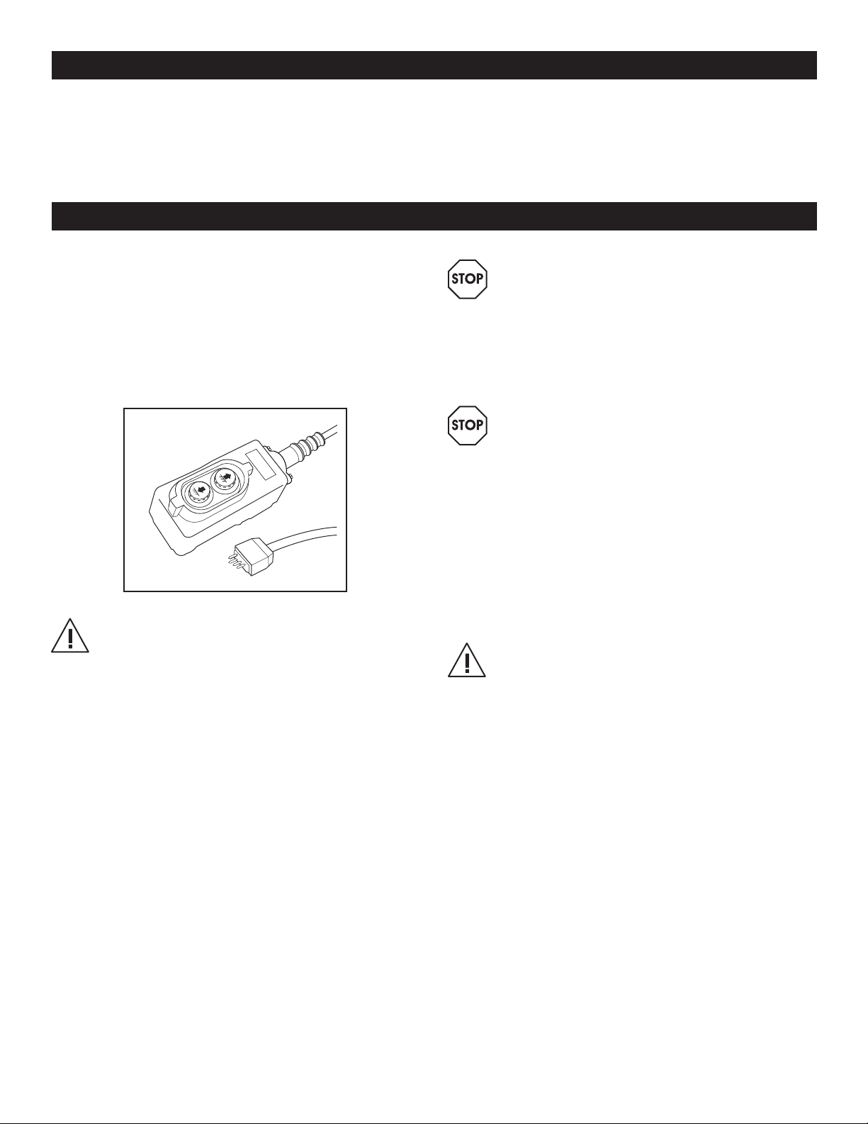
8. To check the level and appearance of the hydraulic
fluid (See Figure 7) raise the unloaded platform
and engage the maintenance bars. All lifts are
equipped with translucent plastic reservoirs making
it possible to visually determine the fluid level without
opening the reservoir cap. The proper fluid level is
checked only when the lift is on the maintenance
bars. Check the fluid level using the fluid level
arrow decal. If required, add oil to the reservoir.
Next, remove the reservoir breather and check the
condition of the oil; it should appear light in color.
The oil should be changed if the color has darkened
or if the oil feels gritty. Obtain an oil sample to feel
between your flngers by dipping a shaft-shaped
object into the top of the reservoir opening. Reinstall
the reservoir breather.
9. Finally, raise the lift and disengage the
maintenance bars by returning them to their stored
position.
CHANGING THE AW32 HYDRAULIC OIL
(EVERY 12 MONTHS)
1. Change the hydraulic oil every 12 months of service
or more often if conditions warrant. The frequency
of fluid change will depend upon the general
working conditions, severity of use and the overall
cleanliness and care given to the lift. To do so, raise
the unloaded platform to its maximum height and
engage the maintenance bars. Lower the lift onto
the maintenance bars. Depress and hold the DOWN
button for several seconds to allow any residual
hydraulic pressure to diminish.
2. Remove the snap ring that secures the upper
cylinder pin and then remove the upper cylinder pin.
3. The hydraulic fluid inside the cylinder needs to be
purged from the system. Disconnect the hydraulic
line from the power unit and place the hose end
into a suitable container that will hold the spent
hydraulic fluid. The cylinder rod can now be pressed
back into the cylinder pushing the fluid out of the
cylinder into the container. Press the rod firmly and
slowly until it has completely bottomed and reattach
the hydraulic line to the power unit.
4. The fluid remaining in the power unit reservoir needs
to be purged from the system as well. Disconnect
the hydraulic line from the cylinder and place it in
the container. Press the UP button and run the power
unit until the fluid is purged from the reservoir. Next,
add a small amount of new hydraulic fluid to the
reservoir and run the pump. Repeat this process until
the old hydraulic fluid is completely purged from the
system. Reattach the hydraulic line to the cylinder.
5. The old hydraulic fluid is considered hazardous
waste and should be handled and disposed of
properly. Clean all spilled oil and thoroughly inspect
the lift and all hydraulic components.
6. Lift is supplied with a quality hydraulic oil with rust
and oxidation inhibitors and anti-wear properties for
use in normal ambient temperatures.
MAINTENANCE CONTINUED
FLUID
LEVEL
Figure 7

PAGE 7 OF 7 0413 IH-3934
CHANGING THE AW32 HYDRAULIC OIL
CONTINUED
7. Fill the reservoir with the new hydraulic fluid and run
t
he motor by pressing the UP button to prime the
pump and extend the hydraulic cylinder. Jog the UP
button to slowly extend the cylinder until the hole in
the cylinder rod lines up with the holes in the cylinder
mounting clevis. Replace the upper cylinder pin and
corresponding snap ring.
8. Raise the lift to its maximum height and disengage
the maintenance bars. Completely raise and lower
the lift 3 times to remove any trapped air from the
hydraulic system.
9. Completely raise the lift and engage the
maintenance bars. Recheck the fluid level
as detailed in the "Monthly Inspection and
Maintenance" section. (See Page 6) The lift is
now ready for use.
MAINTENANCE CONTINUED
TROUBLESHOOTING
PROBLEM CAUSES RECOMMENDATIONS
Forks will not raise
(pump running) No hydraulic fluid in reservoir.
Load too heavy (relief valve operating).
Lowering valve held open.
Fill reservoir.
Reduce load.
Check lower control for malfunction.
Clean and/or replace lowering solenoid.
Platform will not remain
elevated Lower valve held open.
Pump check valve not seated.
Check lower control for malfunction.
Clean and/or replace lowering solenoid.
Clean/repair/replace valve.
Flush outlet check.
Platform will not lower Platform or scissors obstruction.
Lowering valve not opening.
Obstruction in flow limiting valve.
Remove obstruction or reposition lift.
Clean and/or replace lowering solenoid.
Flush flow limiting valves.
Platform lowers too slowly Lowering valve not opening completely.
Obstruction in flow limiting valve(s).
Clean and/or replace lowering solenoid.
Flush flow limiting valve(s).
Cylinder(s) leaking Cylinder seals worn or damaged.
Valves, fitting or hoses loose.
Repack cylinder(s).
Tighten valves, fittings or hoses.
Pump leaking Reservoir overfilled with oil.
Hose or fitting loose.
Drain excess fluid.
Tighten fittings or hoses.
Spongy platform Air in hydraulic circuit. Raise and lower platform several times
to remove air and check fluid level.
πCHICAGO•ATLANTA•DALLAS•LOSANGELES•MINNEAPOLIS•NYC/PHILA•SEATTLE•MEXICO•CANADA
1-800-295-5510
uline.com
This manual suits for next models
1
Table of contents
Other U-Line Lifting System manuals
Popular Lifting System manuals by other brands

AussieCarHoists
AussieCarHoists High-Lift Equipment YL-350W Installation and operation manual

BEG
BEG HS1090 operating instructions

Savaria
Savaria Stairfriend owner's manual

Ravaglioli
Ravaglioli KP440 E Translation of the original instructions

Walker Magnetics
Walker Magnetics BUX BM2 Owners/operators manual and safety instructions

Atlas
Atlas BP10000X Installation & operation manual