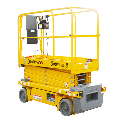
Haulotte OPTIMUM 8 Installation guide

Training manual
OPTIMUM 8 - OPTIMUM 1931 E
4000595920 E 05.17 USA / (1
Training manual
OPTIMUM 8 -
OPTIMUM 1931 E
USA

2 4000595920 E 05.17 USA / (1
OPTIMUM 8 - OPTIMUM 1931 E

3
CONTENTS
Training manual
CONTENTS
A
FOREWORD
1 - Revision. . . . . . . . . . . . . . . . . . . . . . . . . . . . . . . .
8
B
MAIN FEATURES AND FUNCTIONS
1 - Models description. . . . . . . . . . . . . . . . . . . . . . .
9
2 - Primary machine components . . . . . . . . . . . .
10
2.1 - Working area / Range of motion . . . . . . . . . . . . . . . . . . . . . . . . . . . . . . . . 10
2.2 - Transportation . . . . . . . . . . . . . . . . . . . . . . . . . . . . . . . . . . . . . . . . . . . . . . . . 11
2.2.1 - Machine layout . . . . . . . . . . . . . . . . . . . . . . . . . . . . . . . . . . . . . . 11
2.3 - Ground control box . . . . . . . . . . . . . . . . . . . . . . . . . . . . . . . . . . . . . . . . . . . . 12
2.3.1 - Layout . . . . . . . . . . . . . . . . . . . . . . . . . . . . . . . . . . . . . . . . . . . . 12
2.3.2 - HAULOTTE Activ'Screen . . . . . . . . . . . . . . . . . . . . . . . . . . . . . 13
2.3.2.1 - LCD screen . . . . . . . . . . . . . . . . . . . . . . . . . . . . . . . . . . . . . . . . 14
2.4 - Platform control box . . . . . . . . . . . . . . . . . . . . . . . . . . . . . . . . . . . . . . . . . . . 18
2.4.1 - Layout . . . . . . . . . . . . . . . . . . . . . . . . . . . . . . . . . . . . . . . . . . . . 18
C
STUDY OF THE WIRING DIAGRAM
1 - System architecture . . . . . . . . . . . . . . . . . . . . .
21
1.1 - Power circuit . . . . . . . . . . . . . . . . . . . . . . . . . . . . . . . . . . . . . . . . . . . . . . . . . . 22
1.2 - Logic circuit . . . . . . . . . . . . . . . . . . . . . . . . . . . . . . . . . . . . . . . . . . . . . . . . . . . 23
1.3 - Drive circuit . . . . . . . . . . . . . . . . . . . . . . . . . . . . . . . . . . . . . . . . . . . . . . . . . . . 24
1.3.1 - Function of the variators. . . . . . . . . . . . . . . . . . . . . . . . . . . . . . . 26
1.3.1.1 - Control of the traction. . . . . . . . . . . . . . . . . . . . . . . . . . . . . . . . . 27
1.3.1.2 - Control of the pump (other movements). . . . . . . . . . . . . . . . . . . 27
1.3.1.3 - Details of sensors. . . . . . . . . . . . . . . . . . . . . . . . . . . . . . . . . . . . 28
1.3.1.4 - System of unbraking. . . . . . . . . . . . . . . . . . . . . . . . . . . . . . . . . . 28
1.3.1.5 - Detail of the connections . . . . . . . . . . . . . . . . . . . . . . . . . . . . . . 29
1.3.2 - Scissors arm. . . . . . . . . . . . . . . . . . . . . . . . . . . . . . . . . . . . . . . . 31

4
Training manual
2 - List of actuators and sensors . . . . . . . . . . . . .
32
2.1 - Sensors and actuators. . . . . . . . . . . . . . . . . . . . . . . . . . . . . . . . . . . . . . . . . 32
2.2 - Sensors detail. . . . . . . . . . . . . . . . . . . . . . . . . . . . . . . . . . . . . . . . . . . . . . . . . 34
2.2.1 - Limit switchs for potholes . . . . . . . . . . . . . . . . . . . . . . . . . . . . . . 34
2.2.2 - Steering potentiometer. . . . . . . . . . . . . . . . . . . . . . . . . . . . . . . . 35
2.2.3 - Angle transducers . . . . . . . . . . . . . . . . . . . . . . . . . . . . . . . . . . . 36
2.2.4 - Pressure transducer. . . . . . . . . . . . . . . . . . . . . . . . . . . . . . . . . . 37
2.2.5 - Slope sensor . . . . . . . . . . . . . . . . . . . . . . . . . . . . . . . . . . . . . . . 38
2.2.6 - Battery charger. . . . . . . . . . . . . . . . . . . . . . . . . . . . . . . . . . . . . . 38
2.2.7 - Fuses and relays . . . . . . . . . . . . . . . . . . . . . . . . . . . . . . . . . . . . 39
2.3 - Actuators and their location. . . . . . . . . . . . . . . . . . . . . . . . . . . . . . . . . . . . . 40
2.3.1 - List of actuators . . . . . . . . . . . . . . . . . . . . . . . . . . . . . . . . . . . . . 40
2.3.2 - Modules . . . . . . . . . . . . . . . . . . . . . . . . . . . . . . . . . . . . . . . . . . . 40
2.3.3 - Fuses . . . . . . . . . . . . . . . . . . . . . . . . . . . . . . . . . . . . . . . . . . . . . 41
2.3.4 - Inputs . . . . . . . . . . . . . . . . . . . . . . . . . . . . . . . . . . . . . . . . . . . . . 41
2.3.5 - Outputs . . . . . . . . . . . . . . . . . . . . . . . . . . . . . . . . . . . . . . . . . . . 43
2.4 - Cut out conditions of every function. . . . . . . . . . . . . . . . . . . . . . . . . . . . . . 45
2.4.1 - Glossary . . . . . . . . . . . . . . . . . . . . . . . . . . . . . . . . . . . . . . . . . . . 45
2.4.2 - Power supply/commands . . . . . . . . . . . . . . . . . . . . . . . . . . . . . . .46
2.4.3 - Drive. . . . . . . . . . . . . . . . . . . . . . . . . . . . . . . . . . . . . . . . . . . . . . .49
2.4.3.1 - Validation . . . . . . . . . . . . . . . . . . . . . . . . . . . . . . . . . . . . . . . . . . 49
2.4.4 - Steering . . . . . . . . . . . . . . . . . . . . . . . . . . . . . . . . . . . . . . . . . . . .52
2.4.4.1 - Validation . . . . . . . . . . . . . . . . . . . . . . . . . . . . . . . . . . . . . . . . . . 52
2.4.4.2 - Actuators . . . . . . . . . . . . . . . . . . . . . . . . . . . . . . . . . . . . . . . . . . 54
2.4.5 - Arm . . . . . . . . . . . . . . . . . . . . . . . . . . . . . . . . . . . . . . . . . . . . . . .55
2.4.5.1 - Validation . . . . . . . . . . . . . . . . . . . . . . . . . . . . . . . . . . . . . . . . . . 55
2.4.5.2 - Actuators . . . . . . . . . . . . . . . . . . . . . . . . . . . . . . . . . . . . . . . . . . 58
2.4.6 - Brake release . . . . . . . . . . . . . . . . . . . . . . . . . . . . . . . . . . . . . . . .60
2.4.7 - Potholes . . . . . . . . . . . . . . . . . . . . . . . . . . . . . . . . . . . . . . . . . . . .61
2.4.7.1 - Validation . . . . . . . . . . . . . . . . . . . . . . . . . . . . . . . . . . . . . . . . . . 61
2.4.7.2 - Actuators . . . . . . . . . . . . . . . . . . . . . . . . . . . . . . . . . . . . . . . . . . 63

5
CONTENTS
Training manual
D
STUDY OF THE HYDRAULIC SCHEMA
1 - Hydraulic units . . . . . . . . . . . . . . . . . . . . . . . . .
65
1.1 - General overview . . . . . . . . . . . . . . . . . . . . . . . . . . . . . . . . . . . . . . . . . . . . . 65
1.1.1 - The hydraulic components . . . . . . . . . . . . . . . . . . . . . . . . . . . . . 65
1.1.1.1 - Pump unit . . . . . . . . . . . . . . . . . . . . . . . . . . . . . . . . . . . . . . . . . . 65
1.1.1.2 - Selection valve potholes/steering. . . . . . . . . . . . . . . . . . . . . . . . 66
1.1.1.3 - Lifting cylinder valve. . . . . . . . . . . . . . . . . . . . . . . . . . . . . . . . . . 67
E
ADJUSTMENTS
1 - Adjustments with diag pad console . . . . . . . .
69
2 - List of menus . . . . . . . . . . . . . . . . . . . . . . . . . .
70
2.1 - Machine settings . . . . . . . . . . . . . . . . . . . . . . . . . . . . . . . . . . . . . . . . . . . . . . 70
2.1.1 - Speeds and ramps . . . . . . . . . . . . . . . . . . . . . . . . . . . . . . . . . . . 70
2.1.2 - Options. . . . . . . . . . . . . . . . . . . . . . . . . . . . . . . . . . . . . . . . . . . . 70
2.1.3 - Configurations . . . . . . . . . . . . . . . . . . . . . . . . . . . . . . . . . . . . . . 70
2.1.4 - Countries and models . . . . . . . . . . . . . . . . . . . . . . . . . . . . . . . . 70
2.2 - Diagnostic . . . . . . . . . . . . . . . . . . . . . . . . . . . . . . . . . . . . . . . . . . . . . . . . . . . . 70
2.2.1 - Inputs/Outputs . . . . . . . . . . . . . . . . . . . . . . . . . . . . . . . . . . . . . . 70
2.2.2 - States . . . . . . . . . . . . . . . . . . . . . . . . . . . . . . . . . . . . . . . . . . . . . 70
3 - Failures list . . . . . . . . . . . . . . . . . . . . . . . . . . . .
71
3.1 - List of failures per category . . . . . . . . . . . . . . . . . . . . . . . . . . . . . . . . . . . . . 72
4 - Maximum height adjustment. . . . . . . . . . . . . .
87
5 - Cutback speed position height adjustment . .
88
6 - Load management system . . . . . . . . . . . . . . .
89
6.1 - Calibration procedures. . . . . . . . . . . . . . . . . . . . . . . . . . . . . . . . . . . . . . . . . 89
6.2 - Steering . . . . . . . . . . . . . . . . . . . . . . . . . . . . . . . . . . . . . . . . . . . . . . . . . . . . .
91
6.2.1 - Steering calibration procedure . . . . . . . . . . . . . . . . . . . . . . . . . . .92
6.3 - Calibration arm angle sensors (HONEYWELL Sensors). . . . . . . . .
93
6.4 - Calibration arm angle sensors (ELOBAU Sensors) . . . . . . . . . . . . . .
94
7 - Adjustment of pressures . . . . . . . . . . . . . . . . .
95
7.1 - Main pressure. . . . . . . . . . . . . . . . . . . . . . . . . . . . . . . . . . . . . . . . . . . . . . . . . 95
7.2 - The speeds. . . . . . . . . . . . . . . . . . . . . . . . . . . . . . . . . . . . . . . . . . . . . . . . . . . 95

6
Training manual
F
SIMPLIFIED BREAKDOWN GUIDE
1 - No start . . . . . . . . . . . . . . . . . . . . . . . . . . . . . . .
97
2 - No lift . . . . . . . . . . . . . . . . . . . . . . . . . . . . . . . . .
97
3 - No drive . . . . . . . . . . . . . . . . . . . . . . . . . . . . . . .
98
4 - No steering . . . . . . . . . . . . . . . . . . . . . . . . . . . .
98
G
VERSION SUMMARY
1 - Version summary . . . . . . . . . . . . . . . . . . . . . . .
99
2 - List of schematics . . . . . . . . . . . . . . . . . . . . . .
99
3 - List of wiring harnesses . . . . . . . . . . . . . . . . .
99

A
B
C
D
E
F
G
H
I
74000595920 E 05.17 USA / (1
OPTIMUM 8 - OPTIMUM 1931 E
A
- Foreword
Foreword
You are in possession of the summary document provided during the HAULOTTE® technical training
programme. It will allow you to find the information necessary for performing maintenance and repairs on
your HAULOTTE® machine.
The following guide will help you to rapidly access the required chapter.
Section A : Foreword
You will find there the elements as following :
• A resume of any update made since the creation of the manual.
Section B : Main characteristics and functions
You will find there the elements as following :
• The list of the models.
• Their main datas.
• Their overall dimensions.
• Their working envelop.
• Controls boxes.
• Some maintenance topics on specific components (charger, engine ..).
Section C : Study of the wiring diagram
It will include the following elements :
• Structure of the system.
• Localization/photo of each safety components.
• The location/function of each component in schematics.
• Cut out conditions of every function.
Section D : Study of the hydraulic diagram
It will include the following elements :
• The localization of every manifolds.
• The location/function of each component on block.
How to use this document ?
MAINTENANCE AND REPAIR OPERATIONS ON YOUR HAULOTTE® MACHINE MAY ONLY BE PERFORMED BY
TRAINED AND EXPERIENCED TECHNICIANS

8 4000595920 E 05.17 USA / (1
OPTIMUM 8 - OPTIMUM 1931 E
A
- Foreword
Section E : The adjustments
It will include the following elements :
• The way to use/connect the console of diagnostic.
• The list of main menus and its architecture.
• The list of alarms with their explanation.
• Any calibration/settings required for the model of the machine.
• The way to check/adjust the pressures for the model.
Section F : Repair guide
It will include the following elements :
• A summary of every function and items to be checked in case of breakdowns.
Section G : Summary of the versions
It will include the following elements :
• A summary of the different versions made per model.
• Any schematics (electric /hydraulic) linked to the models studied.
• Coloured schematics (electric/hydraulic) per function.
• List of main harnesses in the models studied.
1 - Revision
REVISION EDITION SUBJECT CREATED
BY
VALIDATED
BY
MODIFIED
BY
TRANSLATED
BY LANGUAGE
00 10.16 Creation ASA MGD ASA ITC USA / EN
01 05.17
Add Failures codes, new
schematics, new load
management system
calibration process
ASA MGD ASA ITC USA / EN

A
B
C
D
E
F
G
H
I
94000595920 E 05.17 USA / (1
OPTIMUM 8 - OPTIMUM 1931 E
B
- Main features and functions
Main features and functions
1 - Models description
REGULATION MODELS
ANSI and CSA standards OPTIMUM 1931 E
CE, AS and EAC standards OPTIMUM 8

10 4000595920 E 05.17 USA / (1
OPTIMUM 8 - OPTIMUM 1931 E
B
- Main features and functions
2 - Primary machine components
2.1 - WORKING AREA / RANGE OF MOTION
OPTIMUM 8 - OPTIMUM 1931 E

A
B
C
D
E
F
G
H
I
114000595920 E 05.17 USA / (1
OPTIMUM 8 - OPTIMUM 1931 E
B
- Main features and functions
2.2 - TRANSPORTATION
2.2.1 - Machine layout

12 4000595920 E 05.17 USA / (1
OPTIMUM 8 - OPTIMUM 1931 E
B
- Main features and functions
2.3 - GROUND CONTROL BOX
2.3.1 - Layout
General view
Controls and indicators
MARKING DESCRIPTION FUNCTION
15 E-stop button Pulled out : Ground control box energized
Pushed in : De-energizes control system
43 Horn button Not used
92 Control box activation key selector
Right : Ground control box energized
Center : De-energizes control system
Left : Platform control box energized
93 Battery charging indicator Battery charger status
105 Beacon light (Optional) Move upwards : Flashing light turn ON
Move downwards : Flashing light turn OFF
253 Diagnostic tool socket Connection to the diagnostic tool (HaulotteDiag)
92
253 ACTIV’ Screen
15
43
105
93

A
B
C
D
E
F
G
H
I
134000595920 E 05.17 USA / (1
OPTIMUM 8 - OPTIMUM 1931 E
B
- Main features and functions
2.3.2 - HAULOTTE Activ'Screen
Upon starting and during operation of the machine, the LCD screen "Activ'Screen" located on the
ground control box displays in real time the machine operating status.
HAULOTTE Activ'Screen
Controls and indicators
MARKING DESCRIPTION FUNCTION
1 Platform raising control Platform raises
2 LCD screen Display status of operation of the machine
3 Navigation button Navigation of menu to select function - Scroll up
4 Confirmation button Confirmation of the selected function
5 Cancellation button Go back
6 Platform overload indicator Platform overload indicator
7 Machine fault indicator light Constantly lit in the event of an operation malfunction
8 Navigation button Navigation of menu to select function - Scroll down
9 'Enable Switch' selector Press in and hold : Enable switch
10 Platform lowering control Platform lowers

14 4000595920 E 05.17 USA / (1
OPTIMUM 8 - OPTIMUM 1931 E
B
- Main features and functions
2.3.2.1 - LCD screen
At startup
At startup with the ground or platform controls selected; system initiates a self check :
• Bar gets filled up.
• Home screen comes on with status icon of the machine - okay to proceed functioning the controls.
SYMBOL DESCRIPTION
1Information icons
2Information text
3Status icon of the machine
SYMBOL DESCRIPTION
Battery status
Maintenance use
Fault / alarms
Hour meter

A
B
C
D
E
F
G
H
I
154000595920 E 05.17 USA / (1
OPTIMUM 8 - OPTIMUM 1931 E
B
- Main features and functions
• After pressing on :
• After again pressing on
• Access code screen comes on - refer to maintenance manual for entering the access code
• Validation by pressing on is active only if access code is known and entered - refer to maintenance
manual for the procedure for the different level code useage
SYMBOL DESCRIPTION
1Software part number
2Software version + Screen software version + Screen
version
3Screen identification + Screen software version
4Machine serial number displayed

16 4000595920 E 05.17 USA / (1
OPTIMUM 8 - OPTIMUM 1931 E
B
- Main features and functions
Alarm status
Alarm status displayed as applicable - samples shown below
• Tilt
• Overload
• Low battery

A
B
C
D
E
F
G
H
I
174000595920 E 05.17 USA / (1
OPTIMUM 8 - OPTIMUM 1931 E
B
- Main features and functions
• Present fault
• Platform control box E-stop button pressed in (de-energized)

18 4000595920 E 05.17 USA / (1
OPTIMUM 8 - OPTIMUM 1931 E
B
- Main features and functions
2.4 - PLATFORM CONTROL BOX
2.4.1 - Layout
General view

A
B
C
D
E
F
G
H
I
194000595920 E 05.17 USA / (1
OPTIMUM 8 - OPTIMUM 1931 E
B
- Main features and functions
Controls and indicators
MARKING NAME DESCRIPTION FUNCTION
27 HL800 Tilt indicator Machine on excessive slope
30 HL802 Overload indicator Platform overloaded
43 SA907 Horn button Move upwards and hold to activate horn
46 SB802 E-stop button
Pulled out : Platform control box power supply
energized
Pushed in : De-energizes control system
85 HL903 Fault indicator Fault indicator Faulty or tilting or overloaded machine
91 HL904 Battery charging indicator
Battery charged
Flashing : Batteries have 40 % charge left
Constantly on : Batteries have only 20 % charge left
108 SM901
Movement joystick Move forward : Forward drive or platform raising
Move backwards : Reverse drive or platform lowering
Front axle steering selector Press right side of button : Right-hand steering
Press left side of button : Left-hand steering
110 HL420 Raising / lowering selector On : Raising / Lowering selection activated
Off : Raising / Lowering movement is not selected
111 HL100 Driving selection indicator On : Driving function activated
Off : Driving movement is not selected
112 SA908 2-position selector Move to the left : Platform raising / lowering
Move to the right : Drive movements
123 SA905 'Enable Switch' selector Press in and hold : Associated command is validated
Release : Associated command movement is halted
100%
40%
20%

20 4000595920 E 05.17 USA / (1
OPTIMUM 8 - OPTIMUM 1931 E
B
- Main features and functions
Notes
Other manuals for OPTIMUM 8
2
This manual suits for next models
1
Table of contents
Other Haulotte Lifting System manuals

Haulotte
Haulotte C8 User manual

Haulotte
Haulotte H12SX User manual

Haulotte
Haulotte H23TPX Installation guide

Haulotte
Haulotte H28TJ+ Product guide

Haulotte
Haulotte COMPACT 8 User manual

Haulotte
Haulotte STAR 10 User manual

Haulotte
Haulotte STAR 6 User manual

Haulotte
Haulotte OPTIMUM 8 User manual

Haulotte
Haulotte STAR 6 Installation guide

Haulotte
Haulotte HA16PX Installation guide