Teryair DP 50 AL N Instruction Manual

DP 50 Aluminum and Stainless Steel Construction, All variants
Models Descriptions
DP 50 AL N/B/S/H/V/T Aluminum with Neoprene, Buna N, Santoprene, Hytrel, Viton and PTFE
tments
DP 50 SS N/B/S/H/V/T Stainless Steel with Neoprene, Buna N, Santoprene, Hytrel, Viton and
PTFE tments
DP 50 AL N/B/S/H/V/T DP 50 SS N/B/S/H/V/T
Read this manual carefully before installing, operating or servicing this equipment. It’s the responsi-
bility of the employer to ensure this manual is read by the operator. Please preserve this manual.
is document is issued with Product Serial No
Operation and Maintenance Guide

FF-MM-373-REV - 03
Operation and Maintenance Guide DP 50 Metal Series Page 2
Table of Contents
3 Pump Nomenclature
3 OperangandSafetyInstrucons
4 OperangInstrucons
5 SuggestedLubricants
6 Suggestedsiteseleconandinstallaonrecommendaons
7 Troubleshoong
8 Maintenance
8 DiassemblyandRe-assembly
10 BillofMaterialsforDP50ALNPumps
11 ExplodedViewforDP50ALPump
12 BillofMaterialsforDP50ALBPumps
13 BillofMaterialsforDP50ALSPumps
14 BillofMaterialsforDP50ALHPumps
15 BillofMaterialsforDP50ALVPumps
16 BillofMaterialsforDP50ALTPumps
17 BillofMaterialsforDP50SSNPumps
18 BillofMaterialsforDP50SSBPumps
19 BillofMaterialsforDP50SSSPumps
20 BillofMaterialsforDP50SSHPumps
21 BillofMaterialsforDP50SSVPumps
22 BillofMaterialsforDP50SSTPumps
23 DimensionalData
23 AirValveReplacementKitsforDP50ALX/SSXPumps
23 RepairKitsforDP50ALX/SSXPumps
24 RepairandReplacementKits
25 DeclaraonOfConformityCe
25 TestCercateOfMaterials,Performance
26 EuDeclaraonOfConformity
27 SummeryForTheAtexRangForTeryairAoddModels
29 WarrantyCercate

FF-MM-373-REV - 03
Operation and Maintenance Guide DP 50 Metal Series Page 3
Pump Nomenclature
XX XX XX X X X
Air Valve Type Pump Size Material of Construction Material of
Diaphragm
Bolted or
Clamped
Threading on Inlet
and Outlet
DP - Classic
ADP - Advanced
SDP - MaxFlo
06 - 1/4”
AL - Aluminium
SS - Stainless Steel 316L
PP - Polypropylene
CI - Ductile Iron
B - Nitrile
N - Neoprene
S - Santoprene
T - PTFE
V - Viton
H - Hytrel
B - Bolted
C - Clamped
R- NPT
G - BSPT
P - BSPP
F - Flanged
12 - 1/2”
15 - 1/2”
25 - 1”
40 - 1 - 1/2”
50 - 2 “
75- 3”
100 - 4”
Operating and Safety Instruc-
tions
Warning. Static Electricity
Static sparks can cause explosion resulting in
severe injury or death.
Ground the pump and the pump connec-
tions like hoses and containers into which or
from the uid is being transferred. Connect
the grounding wire to any bolt on the pump.
Check continuity of electrical path to ground
at regular intervals.
Consult local building and electrical codes
for grounding requirements where needed.
Use hoses containing a grounding wire.
Warning: Pump Exhaust
In case of a diaphragm failure, uid being
pumped may spray out from the exhaust
of the pump. is may cause severe injury
depending on the uid being pumped.
If the uid is hazardous, pipe away the
exhaust to a safe remote location using a
generous diameter pipe preferably with a
grounding arrangement, and ret the muer
at the end of this arrangement.
Always wear safety glasses while in the vicin-
ity of an operating pump.
Warning: Overpressure/Haz-
ardous Pressure
Do not exceed the max supply air pressure of
125 PSI.
Make sure all connected hoses and pipelines
are rated to operate safely with the pressures
generated by pump of 125 PSI.
Do not open or handle pump or hoses while
pressurized.
Disconnect air supply line and relieve pres-
sure from the system by carefully opening
discharge and supply lines.
Warning: Hazardous Materials
Do not move a pump that contains hazard-
ous uids trapped inside it. Please observe
prescribed handling and safety codes. Drain
the pump safely, by turning it upside down
and collecting the uid safely, before moving
the pump.
Warning :Explosion
Please check compatibility of uids intended
to be handled with the materials of con-
struction of the pump. Severe reactions and
explosions may occur if materials are
incompatible. Caution: Chemical
compatibility

FF-MM-373-REV - 03
Operation and Maintenance Guide DP 50 Metal Series Page 4
e Teryair Stroke diaphragm pump generates a alternate stroking of the diaphragms against
the uid in the liquid chambers of the Pump. is reciprocatory action is responsible for the
uid being pumped.
It is possible to control the output of the pump by controlling the supply air pressure.
It is also possible to control the output of the pump by throttling action on the uid owing
in the outlet piping by means of a valve. if such a valve is shut completely the pressure in the
discharge piping increases to a point when the pressure at pump discharge equals it and the
pump comes to a stop. is causes no damage to the pump and the pump consumes no more
energy.
Upon opening of the valve, the pump starts reciprocating once again and resumes uid deliv-
ery.
Operating Instructions
Please check that the uid being pumped
is compatible with the wetted parts of the
pump. Refer Cole Parmer compatibility
(http://www.coleparmer.in/Chemical-Re-
sistance) guide for details. Note that
chemical compatibility may change with
temperature; take this into account while
selecting pump material.
Caution: Structural support
Please refer gure 1 and ensure that the
piping system is independently supported
and does not load the pump. e pumps
are not designed to take the continuous
and oen pulsating load of a piping system.
Important to use a exible connection be-
tween rigid piping and pump casings.
Caution: Running dry,
disconnection of hoses
when not in use
Although these pumps can be run dry for
long periods, it is advisable to avoid this
as it causes unnecessary wear of wearing
parts.
Caution: Operator
understanding
Please ensure that all operators have read
this manual and have the required un-
derstanding of safe working practices and
are equipped with safety equipment when
working on/around the pump.
Caution: Using genuine
teryair fittings & spares
Use genuine teryair parts to ensure correct
pump operation and maximize life.
Warning
Conditions for Certification
1. Control of Environmental humidity to
minimize the generation of the static
electricity.
2. Protection from direct airow causing a
charge transfer.
3. Touch with an insulating object to avoid
electrostatic charge hazard.
4. Clean the surface with damp cloth only to
avoid electrostatic charge hazard.

FF-MM-373-REV - 03
Operation and Maintenance Guide DP 50 Metal Series Page 5
Suggested Lubricants
Brand Above 27 Deg C ( From 5 Deg C to 27 Deg C Below 5 Deg C
Shell Toona R 72 Toona R 41 Toona R 27
Mobil Almo 529 Almo 527 Almo 525
Esso -- -- -- Arox EP 65 Arox EP 45
Caltex Rando Oil 150 Rando Oil 100 Rando Oil 46
Texaco Regal Oil F Regal Oil PE Regal Oil B
Daltron Silkolene 881 Silkolene 548 Silkolene 773
Burmah Castrol RD Oil 3 RD Oil Light Megna SPX
BP RD 220 HP60C RD150 HP20C RD80 HP10C
Duckham Garnet 7 Garnet 6 Zero Flo 5
Sternol Merlin 87 Merlin 71 Merlin 54
Petrona Purifoc 53 Purifoc 46 Purifoc 32
Chevron Vistac Oil 18X Vistac Oil 19X Vistac Oil 9X
Caution: Temperature limitations and diaphragm options
Neoprene
Anexcellentgeneral-purposediaphragmforusein
non-aggressiveapplicaonssuchaswater-basedslur-
ries,wellwaterorseawater.Exhibitsexcellentex
lifeandlowcost.Temperaturerange-18°Cto+93°C
(0°Fto+200°F)
Nitile
Excellentforapplicaonsinvolvingpetroleum/
oil-baseduidssuchasleadedgasolines,fueloils,
non-synthechydraulicoils,kerosene,turpenneand
motoroils.
Temperaturerange-12°Cto+82°C(+10°Fto+180°F)
Santoprene
Goodabrasionresistance.Lowcost.Canhandlemild
acidsandalkaliswell.Excellentlowcostalternave
tope.ExcellentsuconcapabilitesExcellentgeneral
purposediaphragm.
Temperaturerange-40°Cto+107°C(-40Fto+225°F)
Hytrel Goodabrasionresistance.Lowcost..Excellentsuc-
oncapabilitesGoodgeneralpurposediaphragm.
Temperaturerange-29°Cto+104°C(-20°Fto+220°F)
Viton
Excellentforuseinapplicaonsrequiringextremely
hottemperatures.Mayalsobeusedwithaggressive
uidssuchasaromacorchlorinatedhydrocarbons
andhighlyaggressiveacids.Especiallywherehigh
suconliisimportant.
Temperaturerange-40°Cto+177°C(-40°Fto+350°F)
PTFE
Excellentchoicewhenpumpinghighlyaggressive
uidssuchasaromacorchlorinatedhydrocarbons,
acids,causcs,ketonesandacetates.
Temperaturerange+4°Cto+104°C(+40°Fto+220°F)

FF-MM-373-REV - 03
Operation and Maintenance Guide DP 50 Metal Series Page 6
Location selection
Pump location must be easily accessible with reasonable
space around for maintenance operations.
Pump dimensional data for each variant is available in
section showing exploded views
Air supply
Compressed air at 90 PSI ( Stroke pumps can take a max
of 125PSI), free from moisture and having an oil mist is
essential. Use of a lter (50 microns), a lubricator and a
regulator is highly recommended and should be installed
as close as possible to the pump inlet.
Ensure correct grade of oil is used in thelubricator bowl.
Too thick oil may slow down the valve shiing mecha-
nism and aect pump performance. See suggested
lubricants on page no5.
Piping
see section on safety if used in hazardous area)
See Figure 1.
Suction side 2 inch or larger, non-collapsible
Delivery side 2 inch or larger.
A minimum number of bends and ttings to be used.
A exible connection between suction, delivery and air
supply piping is highly recommended such that piping
stresses and loads do not transfer to pump housing.
Select piping materials such that chemical compatibility is
maintained with the uid being pumped.
Suction
Ensure that the suction head aer installation is well with-
in the pumps suction capabilities
Muffler
Use of supplied muer is recommended to bring pump
operation sounds down to comfortable levels, in case of
hazardous uids handling, please read section of safety
regarding piping away of exhaust see
Warning: Pump Exhaust) earlier in this manual.
Suggested site selection and installation recommendations
Figure 1

FF-MM-373-REV - 03
Operation and Maintenance Guide DP 50 Metal Series Page 7
Troubleshooting
Serial No Description Causes Remedial Action
1Pump stops and
will not start
Insucient Air Pressure Check air pressure is as recommended
at the pump air inlet
Air Filter Blocked Check if debris has clogged the inlet l-
ter on the FRL unit/pump inlet air valve
( some models have air lter on the air
inlet valve ) and ensure clear passage of
air
Internal damage or excessive wear
on components
roceed to dismantle the pump, examine
component for wear, replace any worn
components, re assemble carefully as
instructed in this manual and re start
the pump.
2Pumps runs slowly,
poor delivery
Cavitation Check if cavitation is occurring in the
suction side, if so reduce suction vacu-
um by slowing down the pump.
Worn Balls and Seats Check proper sealing action of balls
against seals, these components need to
be replaced as a set if they are worn.
Insucient or wrong lubricant in
the air supply.
Ensure that the lubricant is as per the
recommended chart, a thicker lubricant
oen makes the air valve work sluggish-
ly
Internal damage or excessive wear
on components
Proceed to dismantle the pump, exam-
ine component for wear, replace any
worn components, re assemble carefully
as instructed in this manual and re start
the pump.
3Pump air valve
frerzes
Excessive moisture in supply air
line.
Ensure that the dew point of the
supplied air is low enough. Install a
air dryer or moisture separator on the
supply line
4Air bubbles in
pump discharge or
product sprays out
of exhaust vent
Broken Diaphragm
Proceed to dismantle the pump, exam-
ine component for wear, replace any
worn components, re assembly carefully
as instructed in this manual and re start
the pump
mproper seal between inner pis-
tons, outer pistons and sha.
Air leakage into product from
balls / seats area
Air sucked into suction pipeline
due to insuciently tight joints on
suction pipeline.

FF-MM-373-REV - 03
Operation and Maintenance Guide DP 50 Metal Series Page 8
Maintenance
Regular inspection and maintenance schedules will greatly enhance the life of the pump and
will ensure a trouble free and safe working environment with little chance of breakdowns.
Follow the instructions in “Disassembly and Reassembly” of the pump and in the troubleshoot-
ing section.
Use genuine Teryair spares and if possible mention the serial number of the pump when order-
ing spares.
Always replace elastomers as a set, eg diaphragms, balls and seats.
1) Replacement of Diaphragm
a. Unscrew both bolt (26) & nut (27) as shown
in the exploded view and proceed to remove the small
clamp (10). Repeat for the other three small clamps.
Remove the outlet (3) & inlet (2) respectively. Examine
the balls, seals (and seats) for wear.
b. Now unscrew hex socket head bolt (25) &
nut (29) of any one side and proceed to remove the big
clamp (9). Now remove the outer chamber (6). Now
repeat the same procedure to remove the second outer
chamber (6).
c. Now with the help of two spanner hold one
of the across at of one outer ange (5) and rotate the
second outer ange (5) to disassemble it from the sha
assembly. Remove the diaphragm (11), & inner ange
(4). Now pull out the sha assembly out of the sha
housing (1).
*For ALT/SST series hold one of the across at of hex.
Bolt (5A) and rotate the second bolt (5A) to disassemble
it from the sha assembly. Remove backup diaphragm
(11), PTFE diaphragm (11A), Inner spacer (7A) & inner
ange (5). Now pull out the sha assembly out of the
sha housing (1).
Diassembly and Re-assembly

FF-MM-373-REV - 03
Operation and Maintenance Guide DP 50 Metal Series Page 9
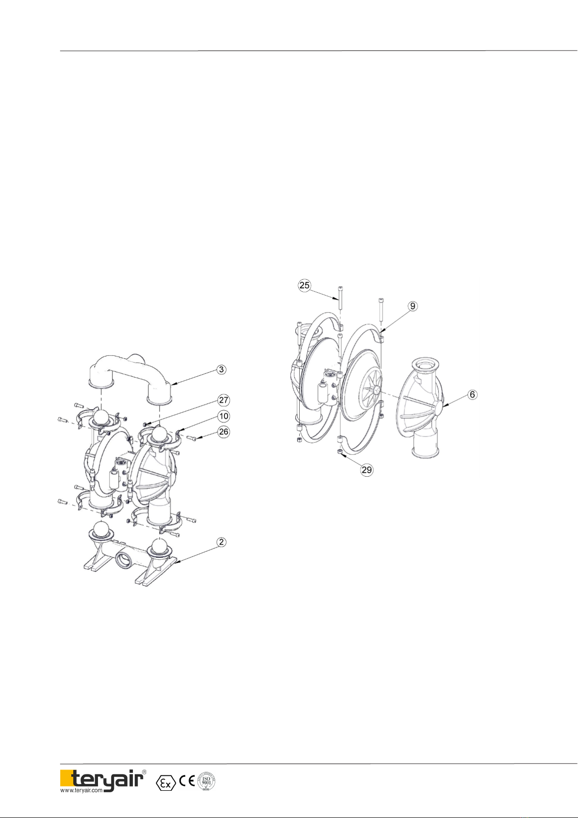
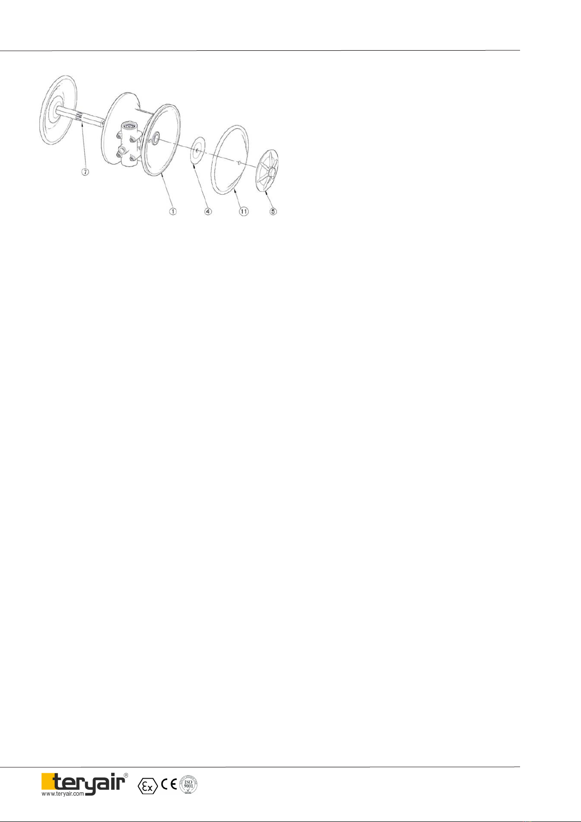
d. Now hold the sha (7) in a vice with proper
packing. Care must be taken not to damage the sha outer
surface. Now remove the outer ange (5) with spanner.
*For ALT/SST series remove the bolt (5A) and remove the
outer ange (5), Backup diaphragm (11), Inner spacer (7A &
PTFE diaphragm (11A).
e. Now replace the diaphragms (11). Ensure that di-
aphragm orientation is correct, i.e. For ALB/ ALN/ALV the
sticker side of the diaphragm (11) to be located in the outer
chamber (6). Now assemble the outer ange (5) in reverse
manner and remove the half sha assembly from vice.
* Refer g. A for ALT & SST model the convex side of outer
ring PTFE diaphragm (11) to be located in outer chamber
(6). For the backup diaphragm (11A) the larger side of outer
ring to be located in sha housing (1) & small in the concave
groove of PTFE diaphragm (11).
* For ALS/ ALH model AIR SIDE marking to be located
toward the sha housing (1).
f. Lubricate the edge of the sha with specied
lubricant. Slowly insert the sha with rotating motion. Care
should be taken not to damage the rubber rings (8).
g. Once the half sha open portion comes out of the
bush, follow the procedure in reverse manner as described in
part (a) & (b) and assemble the pump.
2) Replacement of Shaft O rings
a. For removing the rubber rings from bush, rst
follow the step a, b & c from the diaphragm replacement.
b. Now remove the seals with the help of needle Nose
pliers. Care should be taken not to damage the inner face of
bush.
c. Once all the old seals are have been removed, the
inside of the bushing should be cleaned to ensure no debris
is le that may damage to new seals (Pressurized air is pref-
erable).
d. ese following tools can be used to aid in the
installation of new seals:
• Needle Nose pliers
• Phillips Screwdriver
• Electrical Tape
e. Wrap electrical tape around each leg of the needle
nose pliers (heat shrink may also be used) . is is done to
prevent damaging the inside portion of the new seals.
f. With a new seal in hand, place the two legs of the
nose pliers inside the seal ring. Open the pliers as wide as
the seal diameter will allow, then two ngers pull down on
the top portion of the seal to form kidney bean shape.
g. Lightly clamp the pliers together to hold the seal
into the kidney shape. Be sure to pull the seal into as tight of
a kidney shape as possible, this will allow the seal to travel
down the bushing bore easier.
h. With the seal clamped in the pliers, insert the seal
into the bushing bore and position the bottom of the seal
into the correct groove. Once the bottom of the seal is seated
in the groove, release the clamp pressure on the pliers. is
will allow the seal to partially snap back to its original shape.
i. Aer the pliers are removed, you will notice a slight
bump in the seal shape. Before the seal can be properly
resized, the bump in the seal should be removed as much
as possible. is can be done with either the Phillips screw
driver or your nger, apply light pressure to the peak of the
bump. is pressure will cause the bump to be almost com-
pletely eliminated.
j. Lubricate the edge of the sha with specied lubri-
cant.
k. Slowly insert the sha with rotating motion. is
will complete the resizing of the seals.
l. Perform these steps for the remaining seals.
3) Replacement of Ball seat & Ball
a) Follow the step (a) of diaphragm replacement.
Replace the ball (12) & seat (13) with new one.
* For ALT, SST series change the valve seat
(13) & oring (13A) with new one.
4) Replacement of air valve and oring
of end cap
a) Unscrew commen nut (27) just behind the
washer (28) from the sha housing (1). Remove the air valve
assembly along with the bolt (24). Now remove the circlips
(21) from both ends. Now with the help of bolt (24) pull the
end cap (17) & (19) from both ends. Now slide out the air
valve (16). Change the oring (20) of both end caps.
b) While assembly rst put the end cap with pin (19)
in air valve body (14). Make sure the notch of end cap (19)
matches with the drill hole of body. Push the end cap with
oring (20) gently. Now t the circlip (21). Now slide the air
valve from other side ensuring the drill portion located in
the pin of end cap (19). Now push the end cap (17) with
oring (20) from the other end and t the circlip.
c) You can also change the gasket for air valve body
(15) & blocking pad (22). Now assemble the air valve
assembly in reverse manner. While assembly make sure to
put the spring washer (28) along with the nut (27).

FF-MM-373-REV - 03
Operation and Maintenance Guide DP 50 Metal Series Page 10
ITEM NO PART
NUMBER
DESCRIPTION CG
MODELS
CP
MODELS
31 202 10 06 ADAPTOR 2” BSPT(F) 2
31 202 10 09 ADAPTOR 2” BSPP(F) 2
32 202 04 08 ADAPTOR 3/4” BSPT(F) 1
32 202 04 05 ADAPTOR 3/4” BSPP(F) 1
Above all parts are common for CR (NPT), CG (BSPT) & CP (BSPP) Pumps.
e additional parts for CG (BSPT) & CP (BSPP) pumps model are as follows
Note.
Bill of Materials for DP 50 ALN Pumps
ILLU. NO. PART NO. DESCRIPTION DP50ALN-CR
1 200 10 28 SHAFT HOUSING 1
2 200 40 39 INLET BASE 1
3 200 40 37 OUTLET 1
4 202 10 02 INNER FLANGE 2
5 202 10 03 OUTER FLANGE 2
6 200 40 35 OUTER CHAMBER SIDE 2
7 200 40 15 SHAFT 1
8 200 40 13 RUBBER RINGS 7
9 200 40 47 BIG CLAMP 4
10 200 40 53 SMALL CLAMP 8
11 202 40 41 DIAPHRAGM (NEOPRENE) 2
12 200 40 43 BALL (NEOPRENE) 4
13 200 40 45 SEAL (NEOPRENE) 4
14 202 04 01 AIR VALVE BODY 1
15 200 40 34 GASKET 1
16 202 20 01 AIR VALVE 1
17 200 08 08 VALVE END CAP 1
18 211 13 01 FILTER 1
19 200 08 06 VALVE END CAP WITH PIN 1
20 202 40 02 O RING 2
21 200 90 07S INT CIRCLIP 2
22 200 10 32 BLOCKING PAD 1
23 200 40 31 GASKET 1
24 200 90 25 ALLEN BOLT 4
25 200 40 49 ALLEN BOLT 4
26 200 90 68 ALLEN BOLT 8
27 022 40 21 HEX NUT 12
28 199 90 47 SPRING WASHER 4
29 200 40 30 HEX NUT 4
30 200 97 15 SILENCER 1

FF-MM-373-REV - 03
Operation and Maintenance Guide DP 50 Metal Series Page 11
Exploded View for DP 50 Pump

FF-MM-373-REV - 03
Operation and Maintenance Guide DP 50 Metal Series Page 12
ITEM NO PART
NUMBER
DESCRIPTION CG
MODELS
CP
MODELS
31 202 10 06 ADAPTOR 2” BSPT(F) 2
31 202 10 09 ADAPTOR 2” BSPP(F) 2
32 202 04 08 ADAPTOR 3/4” BSPT(F) 1
32 202 04 05 ADAPTOR 3/4” BSPP(F) 1
Above all parts are common for CR (NPT), CG (BSPT) & CP (BSPP) Pumps.
e additional parts for CG (BSPT) & CP (BSPP) pumps model are as follows
Note.
Bill of Materials for DP 50 ALB Pumps
ILLU. NO. PART NO. DESCRIPTION DP50ALB-CR
1 200 10 28 SHAFT HOUSING 1
2 200 40 39 INLET BASE 1
3 200 40 37 OUTLET 1
4 202 10 02 INNER FLANGE 2
5 202 10 03 OUTER FLANGE 2
6 200 40 35 OUTER CHAMBER SIDE 2
7 200 40 15 SHAFT 1
8 200 40 13 RUBBER RINGS 7
9 200 40 47 BIG CLAMP 4
10 200 40 53 SMALL CLAMP 8
11 202 40 41B DIAPHRAGM (BUNA) 2
12 200 40 43B BALL (BUNA) 4
13 200 40 45B SEAL (BUNA) 4
14 202 04 01 AIR VALVE BODY 1
15 200 40 34 GASKET 1
16 202 20 01 AIR VALVE 1
17 200 08 08 VALVE END CAP 1
18 211 13 01 FILTER 1
19 200 08 06 VALVE END CAP WITH PIN 1
20 202 40 02 O RING 2
21 200 90 07S INT CIRCLIP 2
22 200 10 32 BLOCKING PAD 1
23 200 40 31 GASKET 1
24 200 90 25 ALLEN BOLT 4
25 200 40 49 ALLEN BOLT 4
26 200 90 68 ALLEN BOLT 8
27 022 40 21 HEX NUT 12
28 199 90 47 SPRING WASHER 4
29 200 40 30 HEX NUT 4
30 200 97 15 SILENCER 1

FF-MM-373-REV - 03
Operation and Maintenance Guide DP 50 Metal Series Page 13
Bill of Materials for DP 50 ALS Pumps
ILLU. NO. PART NO. DESCRIPTION DP50ALS-CR
1 200 10 28 SHAFT HOUSING 1
2 200 40 39 INLET BASE 1
3 200 40 37 OUTLET 1
4 202 10 02 INNER FLANGE 2
5 202 10 03 OUTER FLANGE 2
6 200 40 35 OUTER CHAMBER SIDE 2
7 200 40 15 SHAFT 1
8 200 40 13 RUBBER RINGS 7
9 200 40 47 BIG CLAMP 4
10 200 40 53 SMALL CLAMP 8
11 202 41 01 DIAPHRAGM (SANTOPRENE) 2
12 202 41 03 BALL (SANTOPRENE) 4
13 202 41 02 SEAL (SANTOPRENE) 4
14 202 04 01 AIR VALVE BODY 1
15 200 40 34 GASKET 1
16 202 20 01 AIR VALVE 1
17 200 08 08 VALVE END CAP 1
18 211 13 01 FILTER 1
19 200 08 06 VALVE END CAP WITH PIN 1
20 202 40 02 O RING 2
21 200 90 07S INT CIRCLIP 2
22 200 10 32 BLOCKING PAD 1
23 200 40 31 GASKET 1
24 200 90 25 ALLEN BOLT 4
25 200 40 49 ALLEN BOLT 4
26 200 90 68 ALLEN BOLT 8
27 022 40 21 HEX NUT 12
28 199 90 47 SPRING WASHER 4
29 200 40 30 HEX NUT 4
30 200 97 15 SILENCER 1
ITEM NO PART
NUMBER
DESCRIPTION CG
MODELS
CP
MODELS
31 202 10 06 ADAPTOR 2” BSPT(F) 2
31 202 10 09 ADAPTOR 2” BSPP(F) 2
32 202 04 08 ADAPTOR 3/4” BSPT(F) 1
32 202 04 05 ADAPTOR 3/4” BSPP(F) 1
Above all parts are common for CR (NPT), CG (BSPT) & CP (BSPP) Pumps.
e additional parts for CG (BSPT) & CP (BSPP) pumps model are as follows
Note.

FF-MM-373-REV - 03
Operation and Maintenance Guide DP 50 Metal Series Page 14
Bill of Materials for DP 50 ALH Pumps
ILLU. NO. PART NO. DESCRIPTION DP50ALH-CR
1 200 10 28 SHAFT HOUSING 1
2 200 40 39 INLET BASE 1
3 200 40 37 OUTLET 1
4 202 10 02 INNER FLANGE 2
5 202 10 03 OUTER FLANGE 2
6 200 40 35 OUTER CHAMBER SIDE 2
7 200 40 15 SHAFT 1
8 200 40 13 RUBBER RINGS 7
9 200 40 47 BIG CLAMP 4
10 200 40 53 SMALL CLAMP 8
11 202 43 01 DIAPHRAGM (HYTREL) 2
12 202 43 03 BALL (HYTREL) 4
13 202 43 02 SEAL (HYTREL) 4
14 202 04 01 AIR VALVE BODY 1
15 200 40 34 GASKET 1
16 202 20 01 AIR VALVE 1
17 200 08 08 VALVE END CAP 1
18 211 13 01 FILTER 1
19 200 08 06 VALVE END CAP WITH PIN 1
20 202 40 02 O RING 2
21 200 90 07S INT CIRCLIP 2
22 200 10 32 BLOCKING PAD 1
23 200 40 31 GASKET 1
24 200 90 25 ALLEN BOLT 4
25 200 40 49 ALLEN BOLT 4
26 200 90 68 ALLEN BOLT 8
27 022 40 21 HEX NUT 12
28 199 90 47 SPRING WASHER 4
29 200 40 30 HEX NUT 4
30 200 97 15 SILENCER 1
ITEM NO PART
NUMBER
DESCRIPTION CG
MODELS
CP
MODELS
31 202 10 06 ADAPTOR 2” BSPT(F) 2
31 202 10 09 ADAPTOR 2” BSPP(F) 2
32 202 04 08 ADAPTOR 3/4” BSPT(F) 1
32 202 04 05 ADAPTOR 3/4” BSPP(F) 1
Above all parts are common for CR (NPT), CG (BSPT) & CP (BSPP) Pumps.
e additional parts for CG (BSPT) & CP (BSPP) pumps model are as follows
Note.

FF-MM-373-REV - 03
Operation and Maintenance Guide DP 50 Metal Series Page 15
Bill of Materials for DP 50 ALV Pumps
ILLU. NO. PART NO. DESCRIPTION DP50ALV-CR
1 200 10 28 SHAFT HOUSING 1
2 200 40 39 INLET BASE 1
3 200 40 37 OUTLET 1
4 202 10 02 INNER FLANGE 2
5 202 10 03 OUTER FLANGE 2
6 200 40 35 OUTER CHAMBER SIDE 2
7 200 40 15 SHAFT 1
8 200 40 13 RUBBER RINGS 7
9 200 40 47 BIG CLAMP 4
10 200 40 53 SMALL CLAMP 8
11 202 40 41V DIAPHRAGM (VITON) 2
12 200 40 43V BALL (VITON) 4
13 200 40 45V SEAL (VITON) 4
14 202 04 01 AIR VALVE BODY 1
15 200 40 34 GASKET 1
16 202 20 01 AIR VALVE 1
17 200 08 08 VALVE END CAP 1
18 211 13 01 FILTER 1
19 200 08 06 VALVE END CAP WITH PIN 1
20 202 40 02 O RING 2
21 200 90 07S INT CIRCLIP 2
22 200 10 32 BLOCKING PAD 1
23 200 40 31 GASKET 1
24 200 90 25 ALLEN BOLT 4
25 200 40 49 ALLEN BOLT 4
26 200 90 68 ALLEN BOLT 8
27 022 40 21 HEX NUT 12
28 199 90 47 SPRING WASHER 4
29 200 40 30 HEX NUT 4
30 200 97 15 SILENCER 1
ITEM NO PART
NUMBER
DESCRIPTION CG
MODELS
CP
MODELS
31 202 10 06 ADAPTOR 2” BSPT(F) 2
31 202 10 09 ADAPTOR 2” BSPP(F) 2
32 202 04 08 ADAPTOR 3/4” BSPT(F) 1
32 202 04 05 ADAPTOR 3/4” BSPP(F) 1
Above all parts are common for CR (NPT), CG (BSPT) & CP (BSPP) Pumps.
e additional parts for CG (BSPT) & CP (BSPP) pumps model are as follows
Note.

FF-MM-373-REV - 03
Operation and Maintenance Guide DP 50 Metal Series Page 16
Bill of Materials for DP 50 ALT Pumps
ILLU. NO. PART NO. DESCRIPTION DP50ALT-CR
1 200 10 28 SHAFT HOUSING 1
2 200 40 39 INLET BASE 1
3 200 40 37 OUTLET 1
4 200 10 27 INNER FLANGE 2
5 200 10 25 OUTER FLANGE 2
5A 200 27 36S HEX. BOLT 2
6 200 10 34 OUTER CHAMBER SIDE 2
7 200 21 15 SHAFT 1
7A 200 21 71 INNER SPACER 2
8 200 40 13 RUBBER RINGS 7
9 200 40 47 BIG CLAMP 4
10 200 40 53 SMALL CLAMP 8
11 200 36 41T DIAPHRAGM (PTFE) 2
11A 200 40 66N BACK UP DIAPHRAGM 2
12 200 36 43T BALL (PTFE) 4
13 202 27 01 VALVE SEAT 4
13A 202 36 01T 'O' RING (PTFE) 4
14 202 04 01 AIR VALVE BODY 1
15 200 40 34 GASKET 1
16 202 20 01 AIR VALVE 1
17 200 08 08 VALVE END CAP 1
18 211 13 01 FILTER 1
19 200 08 06 VALVE END CAP WITH PIN 1
20 202 40 02 O RING 2
21 200 90 07S INT CIRCLIP 2
22 200 10 32 BLOCKING PAD 1
23 200 40 31 GASKET 1
24 200 90 25 ALLEN BOLT 4
25 200 40 49 ALLEN BOLT 4
26 200 90 68 ALLEN BOLT 8
27 022 40 21 HEX NUT 12
28 199 90 47 SPRING WASHER 4
29 200 40 30 HEX NUT 4
30 200 97 15 SILENCER 1
ITEM NO PART
NUMBER
DESCRIPTION CG
MODELS
CP
MODELS
31 202 10 06 ADAPTOR 2” BSPT(F) 2
31 202 10 09 ADAPTOR 2” BSPP(F) 2
32 202 04 08 ADAPTOR 3/4” BSPT(F) 1
32 202 04 05 ADAPTOR 3/4” BSPP(F) 1
Above all parts are common for CR (NPT), CG (BSPT) & CP (BSPP) Pumps.
e additional parts for CG (BSPT) & CP (BSPP) pumps model are as follows
Note.

FF-MM-373-REV - 03
Operation and Maintenance Guide DP 50 Metal Series Page 17
ITEM NO PART
NUMBER
DESCRIPTION CG
MODELS
CP
MODELS
31 202 07 05S ADAPTOR 2” BSPT(F) 2
31 202 07 07S ADAPTOR 2” BSPP(F) 2
32 202 04 08 ADAPTOR 3/4” BSPT(F) 1
32 202 04 05 ADAPTOR 3/4” BSPP(F) 1
Above all parts are common for CR (NPT), CG (BSPT) & CP (BSPP) Pumps.
e additional parts for CG (BSPT) & CP (BSPP) pumps model are as follows
Note.
Bill of Materials for DP 50 SSN Pumps
ILLU. NO. PART NO. DESCRIPTION DP50SSNCR
1 200 10 28 SHAFT HOUSING 1
2 202 07 01 INLET BASE 1
3 202 07 02 OUTLET 1
4 202 10 02 INNER FLANGE 2
5 202 07 04 OUTER FLANGE 2
6 202 07 03 OUTER CHAMBER SIDE 2
7 200 40 15 SHAFT 1
8 200 40 13 RUBBER RINGS 7
9 200 40 47 BIG CLAMP 4
10 200 40 53 SMALL CLAMP 8
11 202 40 41 DIAPHRAGM (NEOPRENE) 2
12 200 40 43 BALL (NEOPRENE) 4
13 200 40 45 SEAL (NEOPRENE) 4
14 202 04 01 AIR VALVE BODY 1
15 200 40 34 GASKET 1
16 202 20 01 AIR VALVE 1
17 200 08 08 VALVE END CAP 1
18 211 13 01 FILTER 1
19 200 08 06 VALVE END CAP WITH PIN 1
20 202 40 02 O RING 2
21 200 90 07S INT CIRCLIP 2
22 200 10 32 BLOCKING PAD 1
23 200 40 31 GASKET 1
24 200 90 25 ALLEN BOLT 4
25 200 40 49 ALLEN BOLT 4
26 200 90 68 ALLEN BOLT 8
27 022 40 21 HEX NUT 12
28 199 90 47 SPRING WASHER 4
29 200 40 30 HEX NUT 4
30 200 97 15 SILENCER 1

FF-MM-373-REV - 03
Operation and Maintenance Guide DP 50 Metal Series Page 18
ITEM NO PART
NUMBER
DESCRIPTION CG
MODELS
CP
MODELS
31 202 07 05S ADAPTOR 2” BSPT(F) 2
31 202 07 07S ADAPTOR 2” BSPP(F) 2
32 202 04 08 ADAPTOR 3/4” BSPT(F) 1
32 202 04 05 ADAPTOR 3/4” BSPP(F) 1
Above all parts are common for CR (NPT), CG (BSPT) & CP (BSPP) Pumps.
e additional parts for CG (BSPT) & CP (BSPP) pumps model are as follows
Note.
Bill of Materials for DP 50 SSB Pumps
ILLU. NO. PART NO. DESCRIPTION DP50SSB-CR
1 200 10 28 SHAFT HOUSING 1
2 202 07 01 INLET BASE 1
3 202 07 02 OUTLET 1
4 202 10 02 INNER FLANGE 2
5 202 07 04 OUTER FLANGE 2
6 202 07 03 OUTER CHAMBER SIDE 2
7 200 40 15 SHAFT 1
8 200 40 13 RUBBER RINGS 7
9 200 40 47 BIG CLAMP 4
10 200 40 53 SMALL CLAMP 8
11 202 40 41B DIAPHRAGM (BUNA) 2
12 200 40 43B BALL (BUNA) 4
13 200 40 45B SEAL (BUNA) 4
14 202 04 01 AIR VALVE BODY 1
15 200 40 34 GASKET 1
16 202 20 01 AIR VALVE 1
17 200 08 08 VALVE END CAP 1
18 211 13 01 FILTER 1
19 200 08 06 VALVE END CAP WITH PIN 1
20 202 40 02 O RING 2
21 200 90 07S INT CIRCLIP 2
22 200 10 32 BLOCKING PAD 1
23 200 40 31 GASKET 1
24 200 90 25 ALLEN BOLT 4
25 200 40 49 ALLEN BOLT 4
26 200 90 68 ALLEN BOLT 8
27 022 40 21 HEX NUT 12
28 199 90 47 SPRING WASHER 4
29 200 40 30 HEX NUT 4
30 200 97 15 SILENCER 1

FF-MM-373-REV - 03
Operation and Maintenance Guide DP 50 Metal Series Page 19
Bill of Materials for DP 50 SSS Pumps
ILLU. NO. PART NO. DESCRIPTION DP50SSSCR
1 200 10 28 SHAFT HOUSING 1
2 202 07 01 INLET BASE 1
3 202 07 02 OUTLET 1
4 202 10 02 INNER FLANGE 2
5 202 07 04 OUTER FLANGE 2
6 202 07 03 OUTER CHAMBER SIDE 2
7 200 40 15 SHAFT 1
8 200 40 13 RUBBER RINGS 7
9 200 40 47 BIG CLAMP 4
10 200 40 53 SMALL CLAMP 8
11 202 41 01 DIAPHRAGM (SANTOPRENE) 2
12 202 41 03 BALL (SANTOPRENE) 4
13 202 41 02 SEAL (SANTOPRENE) 4
14 202 04 01 AIR VALVE BODY 1
15 200 40 34 GASKET 1
16 202 20 01 AIR VALVE 1
17 200 08 08 VALVE END CAP 1
18 211 13 01 FILTER 1
19 200 08 06 VALVE END CAP WITH PIN 1
20 202 40 02 O RING 2
21 200 90 07S INT CIRCLIP 2
22 200 10 32 BLOCKING PAD 1
23 200 40 31 GASKET 1
24 200 90 25 ALLEN BOLT 4
25 200 40 49 ALLEN BOLT 4
26 200 90 68 ALLEN BOLT 8
27 022 40 21 HEX NUT 12
28 199 90 47 SPRING WASHER 4
29 200 40 30 HEX NUT 4
30 200 97 15 SILENCER 1
ITEM NO PART
NUMBER
DESCRIPTION CG
MODELS
CP
MODELS
31 202 07 05S ADAPTOR 2” BSPT(F) 2
31 202 07 07S ADAPTOR 2” BSPP(F) 2
32 202 04 08 ADAPTOR 3/4” BSPT(F) 1
32 202 04 05 ADAPTOR 3/4” BSPP(F) 1
Above all parts are common for CR (NPT), CG (BSPT) & CP (BSPP) Pumps.
e additional parts for CG (BSPT) & CP (BSPP) pumps model are as follows
Note.

FF-MM-373-REV - 03
Operation and Maintenance Guide DP 50 Metal Series Page 20
Bill of Materials for DP 50 SSH Pumps
ILLU. NO. PART NO. DESCRIPTION DP50SSHCR
1 200 10 28 SHAFT HOUSING 1
2 202 07 01 INLET BASE 1
3 202 07 02 OUTLET 1
4 202 10 02 INNER FLANGE 2
5 202 07 04 OUTER FLANGE 2
6 202 07 03 OUTER CHAMBER SIDE 2
7 200 40 15 SHAFT 1
8 200 40 13 RUBBER RINGS 7
9 200 40 47 BIG CLAMP 4
10 200 40 53 SMALL CLAMP 8
11 202 43 01 DIAPHRAGM (HYTREL) 2
12 202 43 03 BALL (HYTREL) 4
13 202 43 02 SEAL (HYTREL) 4
14 202 04 01 AIR VALVE BODY 1
15 200 40 34 GASKET 1
16 202 20 01 AIR VALVE 1
17 200 08 08 VALVE END CAP 1
18 211 13 01 FILTER 1
19 200 08 06 VALVE END CAP WITH PIN 1
20 202 40 02 O RING 2
21 200 90 07S INT CIRCLIP 2
22 200 10 32 BLOCKING PAD 1
23 200 40 31 GASKET 1
24 200 90 25 ALLEN BOLT 4
25 200 40 49 ALLEN BOLT 4
26 200 90 68 ALLEN BOLT 8
27 022 40 21 HEX NUT 12
28 199 90 47 SPRING WASHER 4
29 200 40 30 HEX NUT 4
30 200 97 15 SILENCER 1
ITEM NO PART
NUMBER
DESCRIPTION CG
MODELS
CP
MODELS
31 202 07 05S ADAPTOR 2” BSPT(F) 2
31 202 07 07S ADAPTOR 2” BSPP(F) 2
32 202 04 08 ADAPTOR 3/4” BSPT(F) 1
32 202 04 05 ADAPTOR 3/4” BSPP(F) 1
Above all parts are common for CR (NPT), CG (BSPT) & CP (BSPP) Pumps.
e additional parts for CG (BSPT) & CP (BSPP) pumps model are as follows
Note.
This manual suits for next models
11
Table of contents
Other Teryair Water Pump manuals

Teryair
Teryair SDP50PPTB Instruction Manual

Teryair
Teryair ADPB 25 PPX Instruction Manual

Teryair
Teryair DP 25 ALS Instruction Manual

Teryair
Teryair ADPB12PPT Instruction Manual

Teryair
Teryair SDP50PPT-BF Instruction Manual

Teryair
Teryair DP 75 AL N Instruction Manual

Teryair
Teryair ADPB06PPT Instruction Manual

Teryair
Teryair DP 12 Metal Series Instruction Manual

Teryair
Teryair ADPB 25 PP Series Instruction Manual

Teryair
Teryair SP10 Instruction Manual