Teryair SDP50PPTB Instruction Manual

Operation and Maintenance Guide
SDP50PPTB, 2" Diaphragm pump
Read this manual carefully before installing, operating or servicing this equipment. It’s the responsibility of the employer to ensure this
manual is read by the operator. Please preserve this manual.
& are trademarks of Teryair Equipment Pvt. Ltd.
Product Sr No.

MM-345-REV - 02
1
Pump Nomenclature
SDP 50 PP T B
B-Bolted
T - PTFE (PTF)
PP - Polypropylene
Size : 12 for 1/2"
Diaphragm Pump
Pump Data
Pump Data A
Model No
Wetted
Material
Diaphragm
Material
Ball Material
Seat
Material
O-ring
Material
Suction
Capacity
Air consumption
@ 90 PSI and Max.
Flow
Weight
SDP50PPTB
PP
Bonded
(Buna+PTFE)
PP
PP
PP
6.0 mtrs
108 C.F.M.
28 Kg
Pump Data B
Pump Data C
Description
Value
Non wetted part
Polypropylene
Center Section
Aluminium
Air inlet detail
3/4” NPT
Air Outlet detail
½'' NPT
Fluid Inlet
2” Flange
Fluid Outlet
2” Flange

MM-345-REV - 02
2
Operating and Safety Precautions
Warning. Static Electricity
Static sparks can cause explosion resulting in
severe injury or death.
Ground the pump and the pump connections like
hoses and containers into which or from the fluid is
being transferred. Connect the grounding wire to
any bolt on the pump.
Check continuity of electrical path to ground at
regular intervals.
Consult local building and electrical codes for
grounding requirements where needed.
Use hoses containing a grounding wire.
Warning: Pump Exhaust
In case of a diaphragm failure, fluid being pumped
may spray out from the exhaust of the pump. This
may cause severe injury depending on the fluid
being pumped.
If the fluid is hazardous, pipe away the exhaust to a
safe remote location using a generous diameter ¾”
pipe preferably with a grounding arrangement, and
refit the muffler at the end of this arrangement.
Always wear safety glasses while in the vicinity of
an operating pump.
Warning: Overpressure/Hazardous
Pressure
Do not exceed the max supply air pressure of 125
PSI.
Make sure all connected hoses and pipelines are
rated to operate safely with the pressures generated
by pump of 125 PSI.
Do not open or handle pump or hoses while
pressurized.
Disconnect air supply line and relieve pressure from
the system by carefully opening discharge and
supply lines.
Warning: Hazardous Materials
Do not move a pump that contains hazardous fluids
trapped inside it. Please observe prescribed
handling and safety codes. Drain the pump safely,
by turning it upside down and collecting the fluid
safely, before moving the pump.
Warning: Explosion
Please check compatibility of fluids intended to be
handled with the materials of construction of the
pump. Severe reactions and explosions may occur
if materials are incompatible.
Caution: Chemical Compatibility
Please check that the fluid being pumped is
compatible with the wetted parts of the pump. Refer
Cole Parmer compatibility
(http://www.coleparmer.in/Chemical-Resistance)
guide for details. Note that chemical compatibility
may change with temperature; take this into account
while selecting pump material.
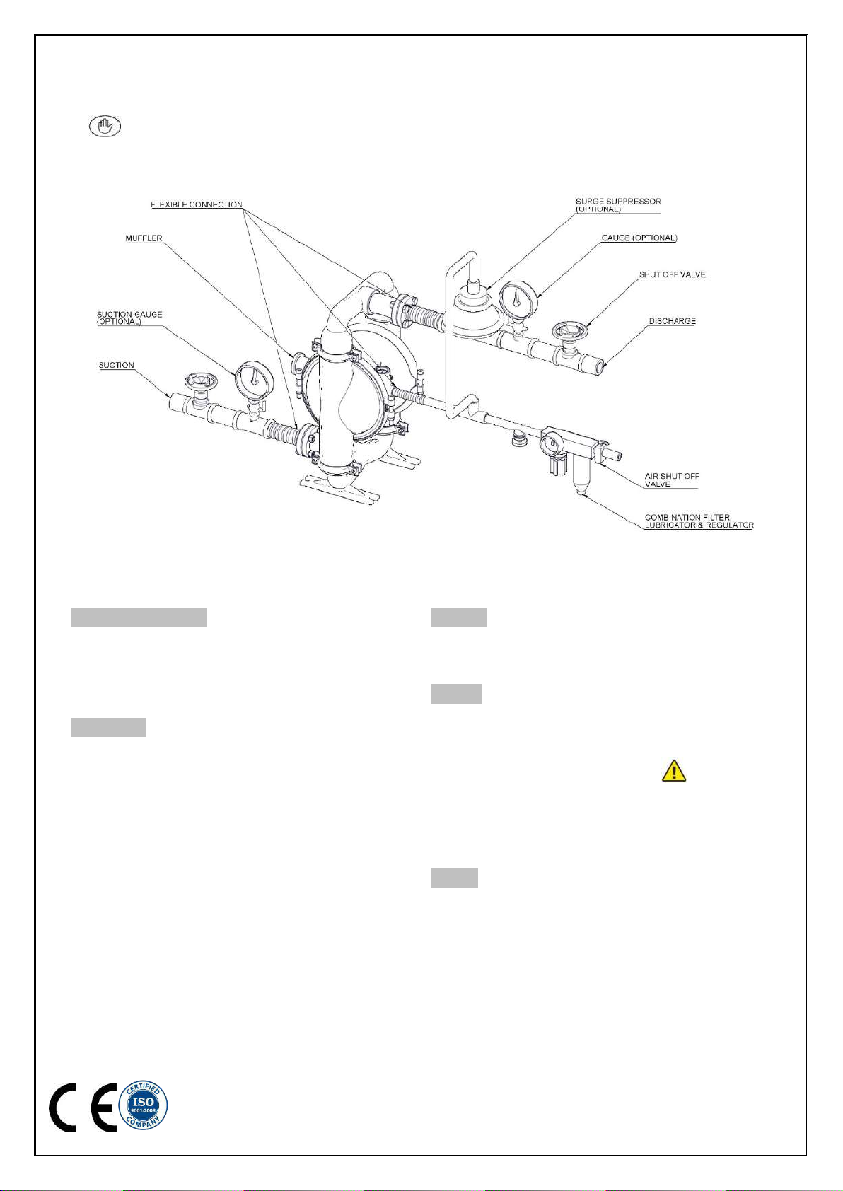
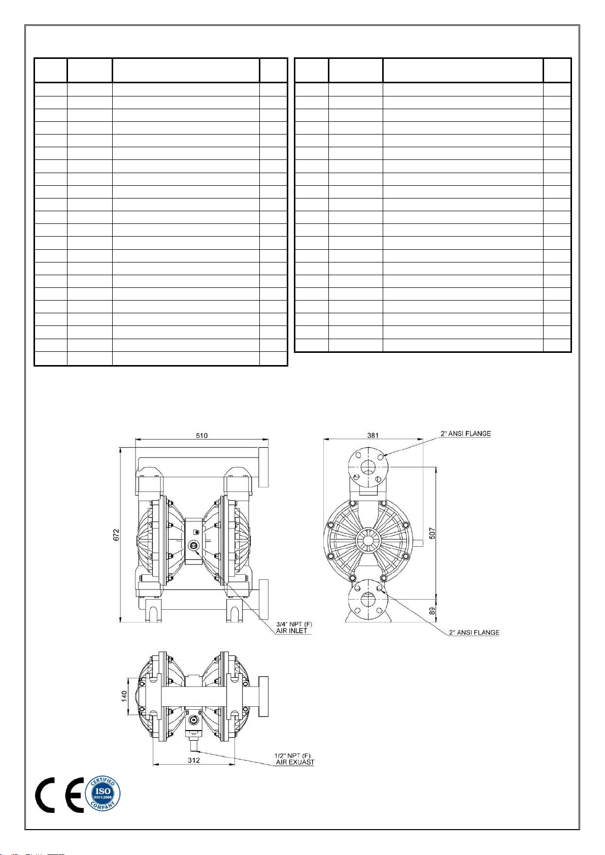
Caution: Structural Support
Please refer figure 1 and ensure that the piping
system is independently supported and does not
load the pump. The pump is not designed to take
the continuous and often pulsating load of a piping
system. Important to use a flexible connection
between rigid piping and pump casings.
Caution: Running dry, disconnection of
hoses when not in use for long periods.
Although these pumps can be run dry for long
periods, it is advisable to avoid this as it causes
unnecessary wear of wearing parts.
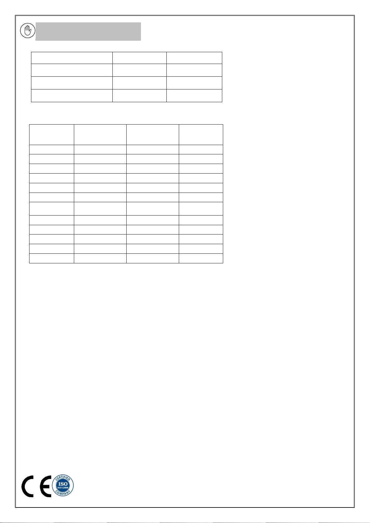
Caution: Tightening Torques and timely
re checking
Outer flange to Shaft 88Nm
Bolt for Outer Chamber and air disc 41Nm
Bolt for Inlet and Outlet 41Nm
Air Valve Body to Housing 3.5Nm
Caution: Operator Understanding
Please ensure that all operators have read this
manual and have the required understanding of
safe working practices and are equipped with safety
equipment when working on/around the pump.
Caution: Using genuine Teryair parts
and fitting as instructed
Use genuine Teryair parts to ensure correct pump
operation and maximize life.

MM-345-REV - 02
3
Caution:Temperature limitations
Elastomer
Minimum allowable
temperature
Maximum allowable
temperature
PTFE
+40° F
+4°C
+225° F
+107°C
Santoprene®
-40° F
-40°C
+225° F
+107°C
Hytrel®
-20° F
-29°C
+150° F
+66°C
Suggested Lubricants
Above 27 deg C
(80 deg F)
5 deg C to 27
deg C (40 degF to
80 degF)
Below 5 deg
C
( 40 deg F)
Shell
Toona R 72
Toona R 41
Toona R 27
Mobil
Almo 529
Almo 527
Almo 525
Esso
-- -- --
Arox EP 65
Arox EP 45
Caltex
Rando Oil 150
Rando Oil 100
Rando Oil 46
Texaco
Regal Oil F
Regal Oil PE
Regal Oil B
Daltron
Silkolene 881
Silkolene 548
Silkolene 773
Burmah
Castrol
RD Oil 3
RD Oil Light
Megna SPX
BP
RD 220 HP60C
RD150 HP20C
RD80 HP10C
Duckham
Garnet 7
Garnet 6
Zero Flo 5
Sternol
Merlin 87
Merlin 71
Merlin 54
Petrofina
Purifoc 53
Purifoc 46
Purifoc 32
Chevron
Vistac Oil 18X
Vistac Oil 19X
Vistac Oil 9X

MM-345-REV - 02
4
Intended use and Prohibitive use
These conditions are adequately described in operating and safety precautions. The list of chemical and fluids are too huge to list here.
Standard industry practice is to refer a accepted chemical compatibility guide such as Cole Parmeretc to establish compatibility. See
section caution: Chemical compatibility earlier in this document.
Suggested site selection and Installation recommendations
Figure 1
Location selection
Pump location must be easily accessible with reasonable
space around for maintenance operations.
Pump dimensional data for each variant is available in
section showing exploded views
Air supply
Compressed air at 90 PSI (Stroke pumps can take a max
of 125PSI), free from moisture and having an oil mist is
essential. Use of a filter (50 microns), a lubricator and a
regulator is highly recommended and should be installed
as close as possible to the pump inlet.
Ensure correct grade of oil is used in the lubricator bowl.
Too thick oil may slow down the valve shifting mechanism
and affect pump performance. See suggested lubricants
below
Suction
Ensure that the suction head after installation is well within
the pumps suction capabilities
Muffler
Use of supplied muffler is recommended to bring pump
operation sounds down to comfortable levels, in case of
hazardous fluids handling, please read section of safety
regarding piping away of exhaust see Warning: Pump
Exhaust) earlier in this manual.
Piping
See section on safety if used in hazardous area)
See Figure 1.
Suction side 2 inch or larger, non-collapsible
Delivery side 2 inch or larger.
A minimum number of bends and fittings to be used.
A flexible connection between suction, delivery and air
supply piping is highly recommended such that piping
stresses and loads do not transfer to pump housing.
Select piping materials such that chemical compatibility is
maintained with the fluid being pumped.

MM-345-REV - 02
5
Operating Instructions
The Teryair Stroke diaphragm pump generates a alternate stroking of the diaphragms against the fluid in the liquid chambers of the
Pump. This reciprocatory action is responsible for the fluid being pumped.
It is possible to control the output of the pump by controlling the supply air pressure.
It is also possible to control the output of the pump by throttling action on the fluid flowing in the outlet piping by means of a valve. if
such a valve is shut completely the pressure in the discharge piping increases to a point when the pressure at pump discharge equals it
and the pump comes to a stop. This causes no damage to the pump and the pump consumes no more energy.
Upon opening of the valve, the pump starts reciprocating once again and resumes fluid delivery.
Troubleshooting
Sr. No
Description
Causes
Remedial action
1
Pump stopped and will not start.
Insufficient Air Pressure
Check air pressure is as recommended at the pump air inlet
Air Filter Blocked
Check if debris has clogged the inlet filter on the FRL unit/pump
inlet air valve ( some models have air filter on the air inlet valve )
and ensure clear passage of air
Internal damage or excessive wear on
components
Proceed to dismantle the pump, examine component for wear,
replace any worn components, re assemble carefully as instructed
in this manual and re start the pump.
2
Pump runs slowly, poor delivery
Cavitation
Check if cavitation is occurring in the suction side, if so reduce
suction vacuum by slowing down the pump.
Worn Balls and Seats
Check proper sealing action of balls against seals, these
components need to be replaced as a set if they are worn.
Insufficient or wrong lubricant in the air
supply.
Ensure that the lubricant is as per the recommended chart, a
thicker lubricant often makes the air valve work sluggishly.
Internal damage or excessive wear on
components
Proceed to dismantle the pump, examine component for wear,
replace any worn components, reassemble carefully as instructed
in this manual and re start the pump.
3
Pump air valve freezes
Excessive moisture in supply air line.
Ensure that the dew point of the supplied air is low enough. Install
an air dryer or moisture separator on the supply line.
4
Air bubbles in pump discharge or Product
spraying out of exhaust
1. Broken Diaphragm
2. Improper seal between inner pistons, outer pistons
and shaft.
3. Air leakage into product from balls / seats area

MM-345-REV - 02
6
4. Air sucked into suction pipeline due to insufficiently
tight joints on suction pipeline.
Proceed to dismantle the pump, examine component for
wear, replace any worn components, re assembly carefully
as instructed in this manual and re start the pump.
Maintenance
Regular inspection and maintenance schedules will greatly enhance the life of the pump and will ensure a trouble free and safe working
environment with little chance of breakdowns.
Follow the instructions clearly for disassembly and assembly of the pump and in the troubleshooting section.
Use genuine teryair spares and if possible mention the serial number of the pump when ordering spares.
Always replace elastomers as a set, eg diaphragms, balls and seats.
Dis-assembly and Re assembly
Shut off air supply and allow residual Pressure to bleed off.
Disconnect air supply
Disconnect suction and discharge piping
Turn pump upside down allow process fluid to drain away. If fluid is hazardous due care should be taken.
Make a mark to indicate the positioning of each liquid chamber relative to the housing.
1) Replacement of Diaphragm
a. Unscrew bolts (23) as shown in the exploded view and proceed to remove
the outlet (3).
b. Unscrew bolts (22) as shown in the exploded view and proceed to remove
the inlet (2).
c. Make sure to collect the Ball (12), Ball seat (13) and Oring (18) and keep it.
d. Now unscrew the bolts (25), (26) and Flange nut (28). This will allow to
remove the Outer chamber (6).
e. Now open the other side Outer chamber (6) in the same manner.
f. Now Hold one of the outer flange (5) by its across flat and rotate the other.
g. Now hold the shaft in a bench vice with proper packing in order not to
damage the shaft. Now remove the second outer flange (5).
h. Now the Bonded diaphragm (11) can be removed and replaced with new
one. Make sure to keep the orientation of diaphragm correct I.e; PTFE side
towards Outer chamber (6) side.
i. Now re-assemble in reverse manner. Insert the shaft assembly in rotating manner into the center piece assembly..
Some drop of recommend oil must be applied in the center piece to have ease in assembly.
j. Care must be taken while fitting the outer chamber (6). Make sure to put the bolt (25) and (26) in proper holes.

MM-345-REV - 02
7
2) Replacement of Shaft O rings
a. For removing the rubber rings (9) from center piece assembly, first follow the steps a, b, c, d, e & f from the
diaphragm replacement. This time need to remove both the diaphragm from any one side and on the other side you
can remove the diaphragm with the shaft.
b. Now remove the seals with the help of needle Nose pliers. Care should be taken not to damage the inner face of bush.
c. Once all the old seals are have been removed, the inside of the bushing should be cleaned to ensure no debris is left
that may damage to new seals (Pressurized air is preferable).
d. These following tools can be used to aid in the installation of new seals:
● Needle Nose pliers
● Phillips Screwdriver
● Electrical Tape
e. Wrap electrical tape around each leg of the needle nose pliers (heat shrink may also be used) . This is done to prevent
damaging the inside portion of the new seals.
f. With a new seal in hand, place the two legs of the nose pliers inside the seal ring. Open the pliers as wide as the seal
diameter will allow, then two fingers pull down on the top portion of the seal to form kidney bean shape.
g. Lightly clamp the pliers together to hold the seal into the kidney shape. Be sure to pull the seal into as tight of a kidney
shape as possible, this will allow the seal to travel down the bushing bore easier.
h. With the seal clamped in the pliers, insert the seal into the bushing bore and position the bottom of the seal into the
correct groove. Once the bottom of the seal is seated in the groove, release the clamp pressure on the pliers. This will
allow the seal to partially snap back to its original shape.
i. After the pliers are removed, you will notice a slight bump in the seal shape. Before the seal can be properly resized,
the bump in the seal should be removed as much as possible. This can be done with either the Phillips screw driver or
your finger, apply light pressure to the peak of the bump. This pressure will cause the bump to be almost completely
eliminated.
j. Lubricate the edge of the shaft with specified lubricant.
k. Slowly insert the shaft with rotating motion. This will complete the resizing of the seals.
l. Perform these steps for the remaining seals.
3) Replacement of Ball seat & Ball
a) Follow the step (a) and (b) of diaphragm replacement. Replace the ball (12) , seat (13) and Oring (18) with new one.

MM-345-REV - 02
8
4) Replacement of secondary shaft assembly
a) For removing the secondary shaft assembly from center piece assembly, first follow the steps a, b, c, d from the
diaphragm replacement and remove the outer chamber (6).
b) Repeat the same procedure to remove the other side also.
c) Remove the oring (39) from both sides of secondary shaft assembly (41).
d) Now if you see there is a center drill mark on one side of the secondary shaft assembly (41). Pull the secondary
shaft assembly (41) from this side only.
e) During assembly make sure to push the secondary shaft assembly (41) from the plain side only into the sleeve (8).
5) Replacement of air valve and oring of end cap
a) Remove the circlip (38) with the help of a circlip opener. Now
use a Bolt with M6 thread to pull the end cap (31) with its oring
(33) out of the air valve body (14).
b) Use the same M6 bolt to pull the air piston assembly (40) with
all its seals. This piston assembly (40)need to replace as a
single piece.
c) In order to remove the end plug assembly (42) with its seals,
remove the circlip (37) and push it. End plug assembly (42)
also need to be replace with seals.
d) Its recommend to change both the orings (33) and (32) during
replacing of internal parts.
Note: Some part of air valve assembly can be done with out removing it from the center piece. In case to replace the whole air
valve assembly unscrew the bolts (35). Refer figure on page no. 9.

MM-345-REV - 02
9
Exploded views
SDP50PPTB

MM-345-REV - 02
10
Bill of Material SDP50PPTB
ITEM
NO.
PART
NUMBER
DESCRIPTION
QTY.
ITEM
NO.
PART
NUMBER
DESCRIPTION
QTY.
1
203 10 01
Centre Piece With Insert
1
22
203 90 04S
Hex Bolt M8x45L -SS
8
1A
203 10 02
Air Disc
2
23
203 90 05S
Hex Bolt M8x70L -SS
8
2
205 08 03
Inlet
1
24
612 90 40S
Plain Washer (M8)-SS
16
3
205 08 02
Outlet
1
25
203 90 06S
Hex Bolt M10x120L -SS
4
4
203 08 06
Inner Flange
2
26
203 90 07S
Hex Bolt M10x80L -SS
12
5
203 08 04
Outer Flange For
2
27
203 90 03S
Plain Washer (M10) 20x10.5x2thk -SS
16
6
205 08 04
Liquid Chamber
2
28
203 90 08S
Flange Nut M10 - SS
16
7
203 21 01
Primary Shaft
1
29
203 90 11S
Square Nut 1/4"-20UNC x 5Thk. SS
4
8
203 21 03
Sleeve For Secondary Shaft
1
30
150 97 35
Muffler
1
*9
200 40 13
Shaft Seal
2
31
203 08 03
End Cap
1
10
203 40 01
Gasket For Centre Piece & Air Disc
2
*32
163 40 01
O Ring (Buna-N)
1
*11
203 60 01
Bonded Diaphragm
2
*33
203 40 05
O Ring (Buna-N)
1
*12
205 36 19
PTFE Ball
4
34
171 27 19S
S.H.C.S. M6-1Px20L- SS
3
*13
203 36 02
Valve Ball Seat
4
35
203 90 10S
H.S.C.S.1/4"-20UNC X 1" (25mm) SS
4
14
203 10 03
Air Valve Body
1
36
612 90 11S
Plain Washer 12.5x6.7x1.2thk SS316
4
*15
203 40 04
Gasket For Air Valve Body
1
37
203 90 12
Ext. Circlip DIN 471 -25 x 1.2- Ch.Pl
1
16
203 10 04
Air Valve Body Cover
1
38
203 90 09
Int. Circlip DIN 472 -56 x 2.0- Ch.Pl
1
*17
203 40 08
Gasket For Air Valve Body Cover
1
*39
022 90 30
O' Ring (Buna-N)
2
*18
203 40 02V
O' Ring - Viton
4
*40
203 98 01
Spool Assembly
1
*19
203 40 03
O' Ring - Buna-N
4
*41
203 98 02
Secondary Shaft Assly.
1
20
203 90 01
Hex Bolt M10x35L Ms Wh Znpl
8
*42
203 98 03
End Plug Assly.
1
21
210 90 36
Plain Washer 22x11x2.2thk Ms Wh ZnPl
8
*Mark indicates the fast moving components which are recommended for stock.
Table of contents
Other Teryair Water Pump manuals

Teryair
Teryair ADPB15PPT Instruction Manual

Teryair
Teryair DP 25 ALN Instruction Manual

Teryair
Teryair DPB40PPT Instruction Manual

Teryair
Teryair ADPB12PPT Instruction Manual

Teryair
Teryair DP 50 AL N Instruction Manual

Teryair
Teryair SP10 Instruction Manual

Teryair
Teryair DP 75 AL N Instruction Manual

Teryair
Teryair DP 12 Metal Series Instruction Manual

Teryair
Teryair ADPB40PPT Instruction Manual

Teryair
Teryair DP 25 ALS Instruction Manual