Tesco TS400 User manual

ELECTRIC VEHICLE
SERVICE EQUIPMENT
(EVSE) TEST SYSTEM
PRODUCT:
CATALOG NO. TS400
SET UP
GUIDE

ELECTRIC VEHICLE SERVICE EQUIPMENT
(EVSE) TEST SYSTEM
QUICK SETUP GUIDE
CATALOG NO. TS400
© 2021 TESCO - The Eastern Specialty Company
All Rights Reserved.
Specifications are subject to change without prior notice.
Revision: 1.0
TESCO –The Eastern Specialty Company
925 Canal Street Bristol, PA, 19007
Phone: 215.228.0500
support@tescometering.com
tescometering.com

SETUP GUIDE
tescometering.com +1 215 228 0500
1
1.1 Introduction
TESCO’s CAT. TS400 Electric Vehicle Service Equipment (EVSE) Test System is a complete
system that consists of the CAT. T4000 EVSE Tester and the CAT. PL4000 Programmable
Load, which tests the accuracy of energy delivery using a transactional mode compatible
with HB44 provisions both for AC and DC.
For complete freedom and test automation, add the PL4000 Programmable Load, a
dedicated load emulator solution providing no-load and adjustable-load modes. Any
compatible EV can also be used as the test load by using the appropriate optional cable.
The Proximity and Pilot Control signal exchanges are fully verified for compliance with
protocol requirements. The EVSE’s GFCI can also be tested by applying a programmable
line-earth fault current up to 200mA.
1.2 Contacting TESCO
For Technical Support or Calibration/Repair, please call 215.228.0500.
You can also send an email to support@tescometering.com with any questions.
To view, print, or download the latest manual supplement, visit www.tescometering.com.

SETUP GUIDE
2
+1 215 228 0500 tescometering.com
1.3 General Safety Summary
This manual contains information and warnings that must be observed to ensure safe operation
and keep the TS400 in a safe condition. Operation or service in conditions or in a manner other
than specified could compromise safety. For the correct and safe use of this device, it is essential
that both operating and service personnel follow accepted safety procedures in addition to the
safety precautions specified, including PPE guidelines.
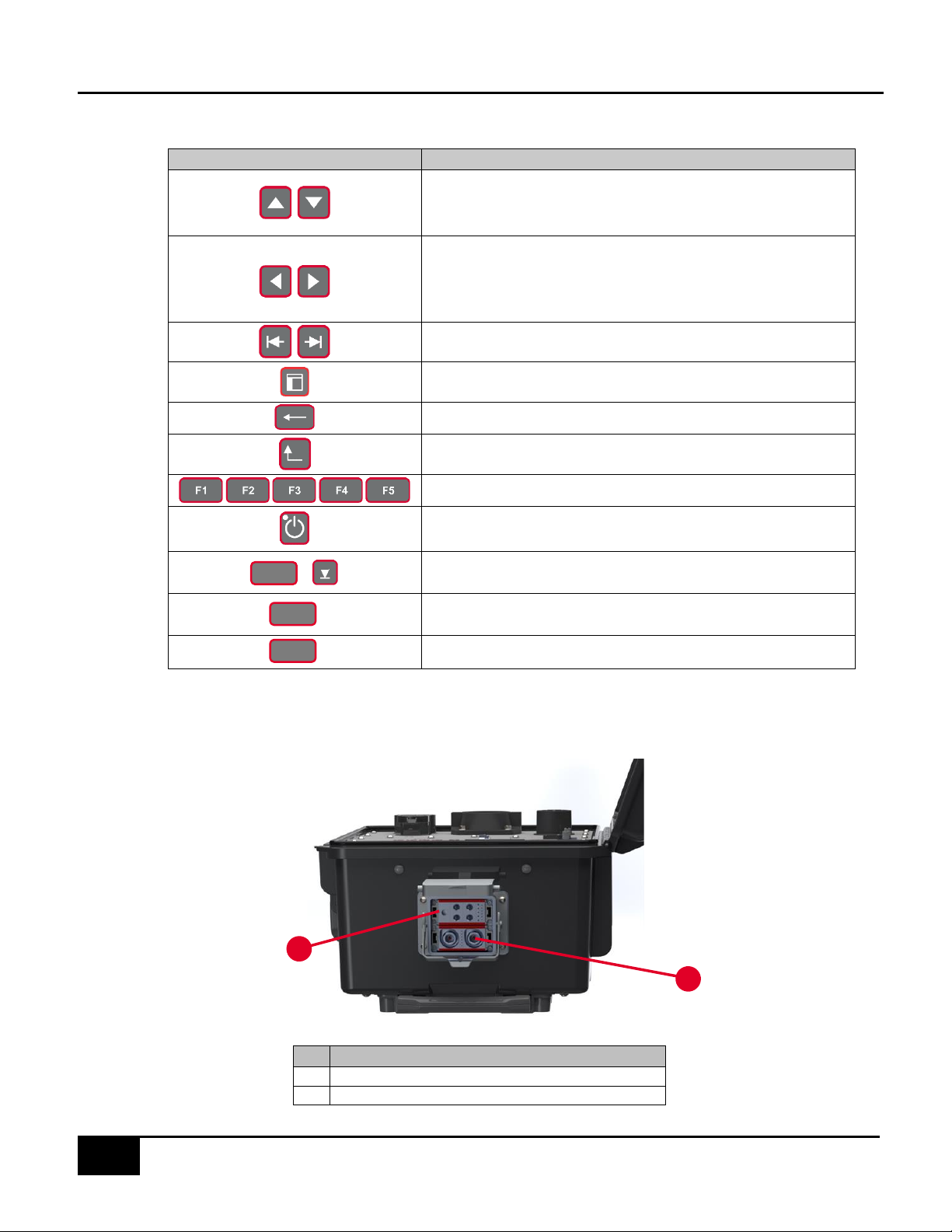
In this manual, a WARNING identifies conditions and actions that pose hazard(s) to the user, while
a CAUTION identifies conditions and actions that may damage the T4000 or the test equipment.
WARNING
To avoid electrical shock, personal injury, or fire hazard:
•Both devices, T4000 and PL4000 must not be switched ON if it is damaged or
suspected to be faulty.
•Do not operate the device in wet, condensing, dusty, or explosive gas conditions.
•If the equipment is used in a manner not specified in this manual, the protection
provided by the T4000 and the PL4000 may be impaired.
•Whenever it is likely that safety protection has been impaired, the devices must be
made inoperative and be secured against any unintended operation. Inform qualified
maintenance or repair personnel.
•Safety protection is likely to be impaired if, for example, the T4000 displays visible
damage or fails to operate normally.
1.4 Description of Safety-related Icons
ICONS
DESCRIPTION
Risk of danger. Important information. See manual.
Hazardous voltage. Risk of electrical shock.
1.5 Unpacking and Inspection
The Instruments are shipped in a container designed to prevent damage during shipping.
Inspect the Instruments carefully for damage, and immediately report any damage to the shipper.
A packing list is included in the packaging. When you unpack the Instruments, check for all the
standard equipment listed and check the shipping order for any additional items ordered. Report
any shortage to the place of purchase, to your distributor, or directly to TESCO.

SETUP GUIDE
tescometering.com +1 215 228 0500
3
1.6 T4000 Front Panel View
#
NAME
1
J1772 DUO Inlet
2
CHADEMO Inlet
3
TESLA Inlet
4
Auxiliary Power
5
7”, 1024x600, high brightness, daylight readable LCD
6
RS232 Com Port
7
Ethernet Com Port
8
USB A Port
9
USB B Port
10
Function Keys
11
Navigation Keys
12
Alphanumeric Keys
13
Power Button
14
Air Inflow
15
Air Outflow
5
6
12
13
11
10
7
8
9
2
1
Table 1.0 T4000 Front Panel Sections
3
14
4
15

SETUP GUIDE
4
+1 215 228 0500 tescometering.com
Navigation Keys
SYMBOL
DESCRIPTION
•Selects the NEXT or PREVIOUS menu item
•Moves the SELECTED LINE UP or DOWN
•Selects an Item from a dropdown menu
•Moves the cursor left/right of the current character in
text boxes
•Moves the selection left/right of the current selected cell
in tables
Selects the NEXT or PREVIOUS TAB item
Moves the focus from one section of the screen to another
Deletes the previous character
Returns to the previous screen
Function keys
Power button. Hold down to turn the device on until the LED
lights up and wait for a few seconds for the screen to load.
Selects a response
Enters a space
Provides context-sensitive help
1.7 T4000 Side Panel (Load Control)
#
NAME
1
AC Connectors
2
DC Connectors
ENTER
SPACE
HELP
Table 1.1 T4000 Side Panel View
2
1

SETUP GUIDE
tescometering.com +1 215 228 0500
5
1.7.1 PL4000 Front Panel
1.7.2 PL4000 Rear Panel
WARNING
PL4000 air outflow can be extremely hot particularly when testing at higher load current or
power. Please allow back space of at least 6.5 feet (2 meters) for the PL4000 air outflow.
#
NAME
1
Power Status Indicator
2
Communication Status Indicator
3
Load Status Indicator
4
Left Fan for Load Heaters (Big Fan 1)
5
CombiTac Connector
6
CombiTac Park Station Holder
7
Strap Handle
8
CombiTac Conduit Holder
9
Right Fan for Load Heaters (Big Fan 2)
10
Fan for Variable Load (VL) Controller (Small
Fan)
#
NAME
1
DC Circuit Breaker
2
AC Circuit Breaker
3
Air Exhaust of Variable Load
4
Left Exhaust for Load Heaters (Big Fan 1)
5
Right Exhaust for Load Heaters (Big Fan 2)
1
2
3
4
9
6
5
8
7
10
Table 1.2 PL4000 Front Panel Sections
Table 1.3 PL4000 Rear Panel Sections
3
4
5
2
1

SETUP GUIDE
6
+1 215 228 0500 tescometering.com
1.8 Set up, Airflow and Cooling Considerations
1.8.1 Setup and Placement
The Instruments are designed to be used sitting on the ground, as long as there is sufficient space
to allow adequate ventilation.
Figure 1.0 Suggested TS400 Setup sitting on the ground.
WARNING
PL4000 air outflow can be extremely hot particularly when testing at higher load current or power.
Please allow a separation distance between the T4000 and PL4000 of at least 2 feet (0.7 meters)
making sure that the COMBITAC cable doesn’t obstruct air outlet.
CAT. T4000 EVSE Tester
CAT. PL4000
Programmable Load
COMBITAC cable

SETUP GUIDE
tescometering.com +1 215 228 0500
7
1.8.2 Airflow
WARNING
Note of the Instrument’s airflow as indicated in the illustration below. This is applicable for both
bench top and rack-mounted use.
PL4000 air outflow can be extremely hot particularly when testing at higher load current or
power. Please allow back space of at least 6.5 feet (2 meters) for the PL4000 air outflow.
Figure 1.1 TS400 Airflow
1.8.3 Cooling Considerations
CAUTION
Damage caused by overheating may occur if the area around the air intake is restricted, the
intake air is too warm, or the air filter becomes clogged.
The inlet and exhaust holes must be clear of obstruction. The air entering the instrument must
be between -4° F (-20° C) and 122° F (50° C). Make sure that exhaust from another instrument is
not directed into the fan inlet. Check and clean the air filter every 30 days or more frequently if
the Instrument is operated in a dusty environment.

SETUP GUIDE
8
+1 215 228 0500 tescometering.com
1.9 Main and Auxiliary Power Supply
The Instrument is powered by an internal rechargeable battery. The battery charge status icon
can be seen in the top right corner of the T4000 LCD screen. The battery can be easily removed
and replaced in the field with a spare one (sold separately).
The battery can be charged in the unit using the provided auxiliary power supply which requires
a 120 VAC outlet. A car charger and a desktop charger (for external charging) are available as
additional accessories.
WARNING
To avoid electrical shock, personal injury, or fire hazard, connect the factory supplied power
cord to a properly grounded AC power outlet to charge the unit when not being used with an
EVSE charger.
Do not charge the unit when it is connected to an EVSE charger.
CAUTION! Only charge the unit with approved power supplies.
1.10Connection and Power-Up
The instrument’s connector employs a “make first, break last” system where upon insertion, the
ground connection is established first before making power connection and maintain ground until
after power connections are broken. This system helps ensure a safer connection.
1.10.1 Sequence of Test Connection and Power-Up
1- Connect the COMBITAC of
PL4000 to the LOAD &
CONTROL connector of T4000.
2- If connected, unplug the AUX
power supply. Then, connect
the Coupler of EVSE to the
J1772 connector of T4000.
3- To Power ON, press the POWER
button for at least 2 seconds.
Figure 1.2 T4000 Connection and Power-Up
1
2
3

SETUP GUIDE
tescometering.com +1 215 228 0500
9
1.10.2 Power-Down and Sequence of Disconnection
WARNING
T4000 must be turned off properly before the connectors are disconnected.
1- To turn off T4000, return to Main Menu and press the power button for at least 2 seconds. A
dialog box appears to confirm shutdown.
2- Disconnect the Coupler of EVSE to the J1772 connector of T4000.
3- Disconnect the CombiTac of PL4000 to the LOAD & CONTROL connector of T4000.

SETUP GUIDE
10
+1 215 228 0500 tescometering.com
1.11 GUI Screen Sections
Upon powering on the T4000, you will find the following Graphical User Interface.
The user interface is divided into four sections. In the screen, any field or button that is grayed out cannot
be changed or accessed by the user.
1.11.1 MAIN MENU
SCREEN
DESCRIPTION
MAIN MENU
The main menu contains the primary functions of the EVSE Tester. Press
a function key to access a menu item.
FUNCTION KEYS
Perform a manual test
View information on the following:
•EVSE
•Site
•Test Results
•Test Sequences
View and change system preferences
View system information
NUMBER
DESCRIPTION
1
Screen Title
2
Status Bar
3
Screen Data
4
Function Buttons
MANUAL MODE
DATABASE
PREFERENCES
SYSTEM INFO
3
2
4
1
Table 3.3.1. CAT. 6330 GUI Sections
MANUAL
MODE
DATABASE
PREFERENCES
SYSTEM INFO

SETUP GUIDE
tescometering.com +1 215 228 0500
11
1.11.2 MANUAL MODE
SCREEN
DESCRIPTION
SELECT CONNECTION TYPE
FUNCTION KEYS
Select CCS1 (AC & DC) connection
type
Select Chademo connection type
Select Tesla connection type
SELECT CHARGE TYPE
FUNCTION KEYS
Select AC charging type
Select DC charging type
SELECT TEST TYPE
FUNCTION KEYS
Select SIMULATION test type
CCS1
CHADEMO
TESLA
AC
DC
SIMULATION
MANUAL MODE
ACCURACY TEST

SETUP GUIDE
12
+1 215 228 0500 tescometering.com
SCREEN
DESCRIPTION
FUNCTION KEYS
Starts the Manual Test
Wait until the test completes and the Test Results shows.
FUNCTION KEYS
Returns to the previous screen
START
BACK
ACCURACY TEST
Other manuals for TS400
2
Table of contents
Popular Service Equipment manuals by other brands

Sealey
Sealey ms1824.v2 instructions

TECALEMIT
TECALEMIT TankQuick eco Translation of the original operating manual

Carlisle Fluid Technologies
Carlisle Fluid Technologies TRISK DeVILBISS TRU-CURE IR3L Service manual

Norma
Norma NORMACONNECT FGR REP E Fitting instructions

Sealey
Sealey DG01 instructions

HENNESSY INDUSTRIES
HENNESSY INDUSTRIES Coats H.I.T. 5000H2 instruction manual