Tesla 1069742-00-A User manual

WALL CONNECTOR, 80A SINGLE PHASE
INSTALLATION MANUAL
THIS MANUAL IS OF THE HIGHEST IMPORTANCE
Approved Markets: North America, Japan

About this Manual...........................2
Communications Regulations.................................2
Errors or Inaccuracies................................................2
Copyrights and Trademarks....................................2
Safety Information..........................3
Important Safety Instructions................................ 3
Warnings.........................................................................3
Cautions..........................................................................3
Notes................................................................................4
Specifications...................................5
Features..............................................6
Optional Circuit Ratings........................................... 6
Self-Monitoring and Recovery................................6
Power Outages.............................................................6
Load Sharing.................................................................6
Planning Your Installation............ 7
Minimum Requirements............................................7
Service Wiring.............................................................. 7
120V Above Ground................................................... 7
Ground Connection.................................................... 7
240V Single-Phase..................................................... 7
208V 3-Phase Wye-Connected............................. 8
240V Three-Phase Delta-Connected.................. 8
277V Three-Phase Wye-Connected.....................9
Determine the Circuit Breaker
Requirements..............................................................10
Choose the Best Location for the Wall
Connector.....................................................................10
Installation Considerations......................................11
Check the Box Contents.............13
Step-by-Step Installation
Instructions...................................... 15
Tools and Materials Required................................15
Overview of Installation Steps..............................15
Install the Low Profile Bracket for Rear
or Bottom Entry Wiring.......................................... 16
Install the Top Entry Bracket for Top
Entry Wiring.................................................................17
Prepare for Installation............................................ 18
Connect the Wiring...................................................19
Set the Operating Current......................................21
Secure the Cover and Power Up.........................22
Troubleshooting............................23
Reset..............................................................................26
Questions?...................................................................27
Appendix A: Testing for
Proper Operation..........................28
Appendix B: Optional
Connection for Load Sharing.. 29
Daisy Chaining Multiple Wall Connectors....... 29
Example of the Communication Wiring.......... 30
Charging Equipment
Limited Warranty...........................31
General Terms............................................................. 31
Limits of Liability.......................................................32
Warranty Enforcement Laws and
Dispute Resolution................................................... 32
Contents

Communications Regulations
This device complies with Part 15 of the FCC
rules and Industry Canada license-exempt RSS
standard(s). Operation is subject to the
following two conditions: (1) This device may
not cause harmful interference and (2) this
device must accept any interference received,
including interference that may cause
undesired operation.
Important: Changes or modifications to
this product not authorized by Tesla
could void the FCC compliance.
Errors or Inaccuracies
To communicate any inaccuracies or
omissions, or to provide general feedback or
suggestions regarding the quality of this
manual, send an email to:
ownersmanualfeedback@teslamotors.com
Copyrights and Trademarks
All information in this document is subject to
copyright and other intellectual property
rights of Tesla Motors, Inc. and its licensors.
This material may not be modified,
reproduced or copied, in whole or in part,
without the prior written permission of Tesla
Motors, Inc. and its licensors. Additional
information is available upon request. The
following are trademarks or registered
trademarks of Tesla Motors, Inc. in the United
States and other countries:
All other trademarks contained in this
document are the property of their respective
owners and their use herein does not imply
sponsorship or endorsement of their products
or services. The unauthorized use of any
trademark displayed in this document or on
the vehicle is strictly prohibited.
About this Manual
2

Important Safety Instructions
This document contains important instructions
and warnings that must be followed when
installing and maintaining the Wall Connector.
Warnings
Warning: Read all the instructions before
using this product.
Warning: This device should be
supervised when used around children.
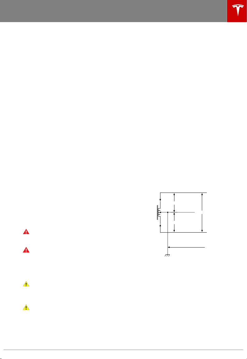
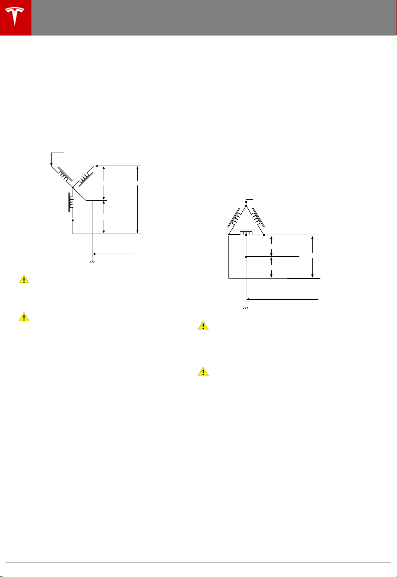
Warning: The Wall Connector must be
grounded through a permanent wiring
system or an equipment grounding
conductor.
Warning: Do not install or use the Wall
Connector near flammable, explosive,
harsh, or combustible materials,
chemicals, or vapors.
Warning: Turn o input power at the
circuit breaker before installing or
cleaning the Wall Connector.
Warning: Use the Wall Connector only
within the specified operating
parameters.
Warning: Never spray water or any other
liquid directly at the wall mounted control
box. Never spray any liquid onto the
charge handle or submerge the charge
handle in liquid. Store the charge handle
in the dock to prevent unnecessary
exposure to contamination or moisture.
Warning: Stop using and do not use the
Wall Connector if it is defective, appears
cracked, frayed, broken, or otherwise
damaged, or fails to operate.
Warning: Do not attempt to disassemble,
repair, tamper with, or modify the Wall
Connector. The Wall Connector is not user
serviceable. Contact Tesla for any repairs
or modification.
Warning: When transporting the Wall
Connector, handle with care. Do not
subject it to strong force or impact or
pull, twist, tangle, drag, or step on the
Wall Connector, to prevent damage to it
or any components.
Warning: Do not touch the Wall
Connector’s end terminals with fingers or
sharp metallic objects, such as wire, tools,
or needles.
Warning: Do not forcefully fold or apply
pressure to any part of the Wall
Connector or damage it with sharp
objects.
Warning: Do not insert foreign objects
into any part of the Wall Connector.
Warning: Use of the Wall Connector may
aect or impair the operation of any
medical or implantable electronic devices,
such as an implantable cardiac
pacemaker or an implantable cardioverter
defibrillator. Check with your electronic
device manufacturer concerning the
eects that charging may have on such
electronic devices before using the Wall
Connector.
Cautions
Caution: Do not use private power
generators as a power source for
charging.
Caution: Incorrect installation and testing
of the Wall Connector could potentially
damage either the vehicle’s Battery
and/or the Wall Connector itself. Any
resulting damage is excluded from the
New Vehicle Limited Warranty and the
Charging Equipment Limited Warranty.
Caution: Do not operate the Wall
Connector in temperatures outside its
operating range of -22°F to 122°F (-30°C
to +50°C).
Safety Information
Safety Information 3

Notes
Note: Ensure that the Wall Connector’s
charging cable is positioned so it will not be
stepped on, driven over, tripped on, or
subjected to damage or stress.
Note: Do not use cleaning solvents to clean
any of the Wall Connector’s components. The
outside of the Wall Connector, the charging
cable, and the connector end of the charging
cable should be periodically wiped with a
clean, dry cloth to remove accumulation of
dirt and dust.
Note: Be careful not to damage the circuit
boards or components during installation.
Safety Information
4

The maximum power rating for the Wall Connector is 20 kW or 80A at 250V AC single-phase
power. Your vehicle can charge from 200V to 277V single-phase power.
Description Specifications
Voltage and Wiring 277V AC single-phase: L1, neutral, and earth
208V or 240V AC single-phase: L1, L2, and earth
Current Maximum output: 80A, 72A, 64A, 56A, 48A, 40A, 36A,
32A, 28A, 24A, 20A, 16A, 12A
Frequency 50 to 60 Hz
Cable Length 8.5' (2.6 m) and 24' (7.4 m)
Wall Connector Dimensions Height: 15.0" (380 mm)
Width: 6.3" (160 mm)
Depth: 5.5" (140 mm)
Top Entry Bracket Dimensions Height: 10.8" (275 mm)
Width: 15.1 " (130 mm)
Depth: 2.0" (50 mm)
Weight (including bracket) 20 lb (9 kg)
Operating Temperature -22°C to 122°C (-30°C to 50°C)
Storage Temperature -40°F to 185°F (-40°C to 85°C)
Enclosure Rating Type 3R
Agency Approvals cULus listed for United States and Canada under file
number E354307, FCC Part 15.
Specifications
Specifications 5

Optional Circuit Ratings
Use a single-phase circuit breaker rated for
100A per phase to obtain the fastest charging.
In certain installation locations, this level of
power isn’t readily available. Therefore, you
can adjust the circuit breaker rating on the
Wall Connector from 15A to 100A (refer to Set
the Operating Current on page 21).
Note: Tesla vehicles must be configured with
optional onboard charging equipment to
accept higher amperages. Contact Tesla if you
have questions about the onboard charging
capabilities of your vehicle.
Self-Monitoring and Recovery
The Wall Connector has a ground monitoring
circuit that continuously checks for the
presence of a safe ground connection and
automatically recovers from faults. Manual
testing and resetting is not required.
Temporary problems such as ground faults or
utility power surges are overcome
automatically. If a residual current fault occurs
that interrupts charging, the Wall Connector
automatically tries to clear the fault and re-
attempt charging.
If the problem is immediately sensed a second
time, the Wall Connector waits 15 minutes
before trying to charge. This process repeats 4
times and if all attempts are unsuccessful,
power is removed and no further attempts are
made. In this case, you will see a red error light
on the front panel (refer to Troubleshooting
on page 23). It is recommended that when
you see a red error light, you power o the
Wall Connector by switching o the upstream
circuit breaker, and then power it back on
again.
The Wall Connector can alternatively be reset
when a red error light is encountered using
the RESET button (refer to Reset on page
26).
Power Outages
If a power outage occurs, the Wall Connector
automatically resumes charging when power
is restored. If the charging cable is plugged
into the vehicle when power is restored, the
lights blink and the unit does not energize the
charging cable for approximately 15 seconds
to three minutes. This prevents the utility grid
from experiencing a large surge when power is
restored and allows vehicles to begin drawing
current at random times, rather than all at
once.
Load Sharing
The Wall Connector provides the capability to
wire 4 Wall Connectors to a single circuit,
giving vehicle owners reassurance that they
can charge multiple vehicles at home (refer to
Appendix B: Optional Connection for Load
Sharing on page 29).
Features
6

Minimum Requirements
Installation of the Wall Connector requires that
you:
• Calculate the existing electrical load to
determine the maximum operating
current.
• Calculate the distance to ensure minimal
voltage drop.
• Obtain any necessary permits from the
local authority that has jurisdiction and
confirm that the follow-up inspection has
been scheduled by an electrician after the
installation is complete.
• Use only copper conductors.
• Use conductors that are sized in
accordance with local wiring regulations.
The selected cable must be able to sustain
periods of constant load of up to 80A.
• Use protective devices. The circuit
protection device chosen must
incorporate a suitable residual-current
device (RCD) and overcurrent protection
in relation to the electrical load selected.
Note: Consult with an electrician to ensure
that the installation meets local regulations.
Service Wiring
120V Above Ground
Warning: The Wall Connector is a single-
phase device. Do not connect all three
phases of a three-phase feed.
Warning: Before installing the Wall
Connector, identify the type of utility
service connection available on site. If you
are unsure about the type of connection
available at the service panel, consult an
electrician, or contact Tesla for assistance.
Caution: The two phases used must each
measure 120V to neutral. Earth ground
must be connected to neutral at only one
point, usually at the breaker panel.
Caution: If a 240V three-phase feed is
from a Delta-connected secondary, the
leg used must have a center tap. This
center tap must be grounded. Only the
two phases on either side of the center-
tapped leg can be used.
Only three wires are connected, but care must
be taken that the service transformer
secondary connection is definitely known, and
that the three wires from the main circuit
breaker panel are correctly connected and
labeled. The illustrations shown are the most
commonly used wiring formats.
Note: The L1, L2, and ground outputs labeled
on the illustrations correspond to the inputs
on the Wall Connector.
Ground Connection
Always connect the Neutral at the service to
Earth Ground. Ground fault protection is not
possible unless the Neutral (center tap on the
service transformer) is connected to an Earth
Ground. If ground is not provided by the
electrical service, you must install a grounding
stake nearby. the grounding stake must be
connected to the ground bar in the main
breaker panel, and Neutral connected to
Ground at that point.
240V Single-Phase
L2
L1
120V
120V
GND
240V
NEUTRAL
(NOT USED)
Note: Illustrations in this document are for
demonstration purposes only.
Planning Your Installation
Planning Your Installation 7

208V 3-Phase Wye-Connected
With a Wye-connected secondary, any two of
the legs can be used to provide 208V to the
Wall Connector. For example, L1 and L2, or L1
and L3, or L2 and L3. The two used phases
must each measure 120V to neutral.
Note: A current-carrying neutral is not
required.
120V 208V
120V
L1
NEUTRAL
(NOT USED)
L3 (NOT USED)
L2 (NOT USED)
GND
Caution: The unused leg (L3 in the
illustration) must remain open. Do not
connect to a neutral bar, or to earth
ground.
Caution: The center point of the three
phases (normally used as neutral) must
be grounded to earth at only one point.
This is usually at the breaker panel.
240V Three-Phase Delta-Connected
With the delta connection, one leg must be
center tapped, and only the two phases on
either side of the center tap can be used. The
two used phases must each measure 120V to
neutral.
Consult the transformer manufacturer’s
literature to verify that the single leg can
supply the required power.
Note: The Wall Connector’s contactor closes
only if it detects the presence of an earth
ground wire connected to a neutral point on
the transformer secondary.
L1
L2
GND
120V
120V
240V
L3 (NOT USED)
NEUTRAL
(NOT USED)
Caution: The third line (L3 in the
illustration) of the delta is 208V, with
respect to neutral, and is sometimes
referred to as a “stinger.” Do not use this
third line.
Caution: Do not use a three-phase delta-
connected transformer secondary
without a center tap on one leg. No
neutral point is available for the required
earth ground connection.
Planning Your Installation
8

277V Three-Phase Wye-Connected
With a Wye-connected secondary, any leg
along with neutral can be used to provide
277V to the Wall Connector. For example, L1
and N, or L2 and N, or L3 and N.
277V 480V
277V
L1
NEUTRAL
L3 (NOT USED)
L2 (NOT USED)
GND
Caution: The unused legs (L2 and L3 in
the illustration) must remain open. Do not
connect to neutral or to earth ground.
Caution: The center point of the three
phases (normally used as neutral) must
be grounded to earth at only one point.
This is usually at the breaker panel.
Planning Your Installation
Planning Your Installation 9

Determine the Circuit Breaker
Requirements
To determine the type of upstream circuit
breaker you need, examine the distribution
panel or circuit breaker box to identify the
amperage available at the installation site.
The Wall Connector has an internal rotary
switch that allows you to adjust its operating
current (refer to Set the Operating Current on
page 21). The circuit breaker should be rated
for the continuous current of: 12, 16, 20, 24, 28,
32, 36, 40, 48, 56, 64, 72, and 80A.
Choose the Best Location for the
Wall Connector
Determine the parking location of the vehicle
to ensure that the charge cable reaches the
charge port.
• In an enclosed garage, typically on the
vehicle's charge port side.
• In a well-ventilated area. Avoid installation
in an enclosed box, or adjacent to hot
appliances.
Note: The Wall Connector is approved for
outdoor use. Protection from rain is
recommended but not required.
Planning Your Installation
10

Installation Considerations
Three methods are available to install the Wall Connector. The location of the conduit determines
which installation method to follow. If the conduit runs along the floor or low on the wall, use the
bottom entry configuration. If the conduit comes from inside the wall, use the rear entry
configuration. If the available conduit comes from the ceiling, use the top entry installation.
Note: Throughout the manual, “conduit” is used as the standard term for the protective tubing
that houses the service wiring. In regions where conduit is not used (Europe for example), a cable
comprised of service wiring enclosed in a protective jacket may be substituted for conduit if
allowed by local regulations.
Here are some additional guidelines:
• Conduit openings are sized for 1" (25 mm) conduit.
• Conduit needs to be metal and flame retardant.
• Use an appropriate circuit breaker.
• To keep the housing weatherproof, use cable glands.
• Use a UL approved conduit hub, Eaton HUB3 or equivalent is recommended.
Bottom or Rear Entry
Planning Your Installation
Planning Your Installation 11

Top Entry
Planning Your Installation
12

The shipping box contains parts for all installation methods, as well as this manual. If any parts are
damaged or missing, contact Tesla (refer to Questions? on page 27).
Note: Not shown is the supplied cardboard template.
1 2 3 4
5 6 7 8 9
10 11 12 13 14
Item Description (Quantity)
1 Wall Connector
2 Top entry bracket*
3 Low profile bracket **
4 Low profile bracket screws (2) **
5 Bottom or rear entry power conduit plug
6 Bottom or rear entry signal conduit plug
7 Top entry signal conduit plug*
8 Top entry power conduit plug*
9 Bottom conduit sealing gasket*
10 Top bracket-to-housing screw covers (2)
11 Bottom bracket-to-housing screw covers (2)
Check the Box Contents
Check the Box Contents 13

Item Description (Quantity)
12 Bottom bracket-to-housing screws (2)
13 Top bracket-to-housing screws (2)
14 Top entry bracket mounting screws (2)*
* Items used in only top entry installations.
** Items used in only bottom or rear entry installations.
Check the Box Contents
14

Tools and Materials Required
Before installing the Wall Connector, gather the following tools and materials:
• Pencil or marker
• Hole punch (optional, to push through cardboard template)
• Wire stripper
• Voltmeter or digital multimeter (to measure AC voltage at the installation site)
• Phillips screwdriver
• Small flathead screwdriver
• Large flathead screwdriver (optional, to remove plastic knock-outs)
• T20 security pin Torx driver
• T10 Torx driver
• M20 and M32 cable glands (also known as sealing hubs)
• Ferrules (the diameter of the ferrule depends on the diameter of the power wiring and the
construction)
• Wiring (use twisted pair communication cable, for a maximum of 49 ft (15 m) between Wall
Connectors)
Note: Tesla recommends that you use a shielded cable to limit potential interference.
• Level
• Machine drill
Overview of Installation Steps
Warning: After you run service wiring to the installation site using metal flame retardant
conduit, install the appropriate upstream circuit breaker, TURN OFF AND VERIFY POWER IS
OFF BEFORE CONTINUING.
Then follow these steps to install the Wall Connector:
• Install the Low Profile Bracket for Rear or Bottom Entry Wiring on page 16
• Install the Top Entry Bracket for Top Entry Wiring on page 17
• Prepare for Installation on page 18
• Connect the Wiring on page 19
• Set the Operating Current on page 21
• Secure the Cover and Power Up on page 22
Step-by-Step Installation Instructions
Step-by-Step Installation Instructions 15

Install the Low Profile Bracket for
Rear or Bottom Entry Wiring
Use the low profile bracket, shown below, to
wire the Wall Connector from the rear or
bottom.
1. Use the low profile bracket as a guide to
mark the location on the wall for the
mounting screws.
• Use a level to ensure that the marks
are perfectly vertical.
• Space the holes 4.5" (114 mm) apart.
• For U.S.A. installations, position the
bracket so that the Wall Connector is
located at a maximum of 60" (150
cm)from floor level. The minimum
height is 18" (45 cm) if mounting
indoors, and 24" (60 cm) if mounting
outdoors.
• If using rear entry conduit, use at least
one set of the edge mounting holes so
that the conduit does not interfere
with the wall stud.
• If using bottom entry conduit, use the
center two mounting holes.
Note: Ensure that the minimum and
maximum height of the bracket is carefully
selected. It should be installed out of the
way of any reasonably foreseeable
impacts.
2. Attach the bracket using fasteners that
are appropriate for the type of wall
material, drilling pilot holes if necessary.
Use the supplied screws only if mounting
the bracket directly to a wooden stud. If
mounting to another type of wall (hollow,
masonry, etc.), use fasteners that are long
enough to securely anchor the Wall
Connector and can hold at least 80 lb (36
kg).
Step-by-Step Installation Instructions
16

Install the Top Entry Bracket for Top
Entry Wiring
The top entry bracket enables you to route the
service wiring into the Wall Connector
enclosure from the top of the enclosure, as
shown below.
1. Use the cardboard template and a level as
a guide to mark the location on the wall
for the mounting screws.
• Use a level to ensure that the marks
are perfectly vertical.
• Space the holes 6.1" (155 mm) apart.
• Position the bracket so that the Wall
Connector is located at a maximum of
60" (150 cm) from floor level. The
minimum height is 18" (45 cm) if
mounting indoors, and 24" (60 cm) if
mounting outdoors.
Note: Ensure that the minimum and
maximum height of the bracket is carefully
selected. It should be installed out of the
way of any reasonably foreseeable
impacts.
2. (Optional) There are two additional
mounting holes. To use these holes, use a
flat-head screwdriver to knock-out the
plastic that is closing the holes. These
holes are spaced 2.75" (70 mm) apart.
3. Attach the bracket using fasteners that
are appropriate for the type of wall
material, drilling pilot holes if necessary.
Use the supplied screws only if mounting
the bracket directly to a wooden stud. If
mounting to another type of wall (hollow,
masonry, etc.), use fasteners that are long
enough to securely anchor the Wall
Connector and can hold at least 80 lb (36
kg).
Step-by-Step Installation Instructions
Step-by-Step Installation Instructions 17

Prepare for Installation
Follow these instructions to remove the cover
and route the service wiring into the Wall
Connector.
1. Use a T10 Torx driver to remove the screw
at the bottom of the outer cover. Carefully
disengage the snaps on the sides and top
using a flathead screwdriver and
completely remove the cover. Save the
screw and cover for reassembly.
2. Use a T20 security pin Torx driver to
remove the six screws on the sealing
cover. Carefully remove the sealing cover
and disconnect the ribbon cable. Save the
screws and cover for reassembly.
Caution: Do not allow the sealing
cover to hang from the ribbon cable.
Doing so can damage the ribbon
cable or its connectors.
3. For top entry configuration, install the
wiring to the terminal block in the top
entry bracket as shown in Connect the
Wiring on page 19, then return to this
section and proceed to the next step. For
back or bottom entry configurations, skip
to the next step.
4. Place and hold the Wall Connector on the
bracket, ensuring that all four mounting
tabs are properly aligned.
5. Use a T20 Torx driver to install the two
top housing mounting screws. Push the
cosmetic screw covers into place.
6. Use a T20 Torx driver to install the two
bottom housing mounting screws. Push
the cosmetic screw covers into place.
Step-by-Step Installation Instructions
18

Connect the Wiring
Note: Consult with your local electrician or
refer to your local code for proper wire sizing
appropriate for the currents in your Wall
Connector.
Note: It is the installer's responsibility to
identify whether additional grounding is
required to ensure that local regulations are
met. Grounding must be installed at the power
source and not at the cable entry to the Wall
Connector.
Warning: Do not connect service wiring
until you have read and fully understand
the concepts described in Service Wiring
on page 7. If you are uncertain about the
type of power available at the service
panel, consult an electrician, or contact
Tesla for assistance.
1. Turn o the power.
Warning: RISK OF ELECTRIC SHOCK!
Before continuing, use a voltmeter to
ensure the power is o by confirming
that NO VOLTAGE is present at the
service wiring or terminals.
2. For top entry installation, pull the service
wiring into the top entry bracket or the
Wall Connector. Use a 1" (25 mm) cable
gland to seal the power conduit or cable.
For 80A operation, use 2AWG 194°F
(90°C) rated copper wire or follow local
regulations.
Note: The meaning of wiring colors might
vary from country to country. Follow all
applicable national and local regulations
concerning wiring color codes.
The following illustration shows an
example of the wiring for the top entry
bracket.
The following illustration shows an
example of the wiring for the low profile
bracket.
3. Strip the service wires going to the
terminal block on the top entry bracket
3/4" (18 mm). Ferrules are recommended.
Note: For top entry installation, the
flexible pre-installed wires that go from
the top entry bracket to the housing are
already terminated and do not need to be
stripped.
Step-by-Step Installation Instructions
Step-by-Step Installation Instructions 19
Table of contents
Other Tesla Batteries Charger manuals

Tesla
Tesla QC50 User manual

Tesla
Tesla TI45014D User manual

Tesla
Tesla WALL CONNECTOR User manual

Tesla
Tesla Wall Connector Gen 3 User manual

Tesla
Tesla WC4 User manual

Tesla
Tesla WALL CONNECTOR User manual

Tesla
Tesla TI150 Series User manual

Tesla
Tesla WC1 User manual

Tesla
Tesla Powerwall User manual

Tesla
Tesla Gen 3 Wall Connector User manual