Tesla Powerwall User manual

POWERWALL INSTALLATION MANUAL
FOR POWERWALL 1067000-00-C WITH SMA AND SOLAREDGE INVERTERS

©2016 TESLA MOTORS, INC. All rights reserved.
All information in this document is subject to copyright and other intellectual property rights of Tesla Motors, Inc.
and its licensors. This material may not be modified, reproduced or copied, in whole or in part, without the prior
written permission of Tesla Motors, Inc. and its licensors. Additional information is available upon request. The
following are trademarks or registered trademarks of Tesla Motors, Inc. in the United States and other countries:
All other trademarks contained in this document are the property of their respective owners and their use herein
does not imply sponsorship or endorsement of their products or services. The unauthorized use of any trademark
displayed in this document or on the product is strictly prohibited.
TESLA TESLA MOTORS POWERWALL
For the latest Powerwall installation documents in all
supported languages, go to:
www.teslamotors.com/support/powerwall-installer
To secure the full 10-year product warranty for the owner, be
sure to register Powerwall online.
Warning: Read this entire document before installing or
using Powerwall. Failure to do so or to follow any of the
instructions or warnings in this document can result in
electrical shock, serious injury, or death, or can damage
Powerwall, potentially rendering it inoperable.
PRODUCT SPECIFICATIONS
All specifications and descriptions contained in this document are verified to be accurate at
the time of printing. However, because continuous improvement is a goal at Tesla, we reserve
the right to make product modifications at any time.
The images provided in this document are for demonstration purposes only. Depending on
product version and market region, details may appear slightly different.
ERRORS OR OMISSIONS
To communicate any inaccuracies or omissions in this manual, please send an email to:
ELECTRONIC DEVICE: DO NOT THROW AWAY
Proper disposal of batteries is required. Refer to your local codes for disposal
requirements.
MADE IN THE USA

Important Safety Instructions............................................................................. 2
SYMBOLS IN THIS DOCUMENT..................................................................................................................................... 2
GENERAL INFORMATION................................................................................................................................................ 2
ENVIRONMENTAL CONDITIONS...................................................................................................................................3
Specifications............................................................................................................ 4
ELECTRICAL SPECIFICATIONS..................................................................................................................................... 4
ENVIRONMENTAL SPECIFICATIONS.......................................................................................................................... 4
MECHANICAL SPECIFICATIONS................................................................................................................................... 4
Site Requirements....................................................................................................5
PHYSICAL REQUIREMENTS............................................................................................................................................ 5
TEMPERATURE REQUIREMENTS..................................................................................................................................5
INSTALLATION REQUIREMENTS.................................................................................................................................. 5
MINIMUM SPACE REQUIREMENTS...............................................................................................................................6
Step-by-Step Installation Instructions............................................................. 7
REQUIRED TOOLS.............................................................................................................................................................. 7
STEP 1 - REMOVE THE LID AND BOTTOM COVER................................................................................................ 8
STEP 2 - REMOVE THE SPLASH COVER....................................................................................................................9
STEP 3 - SET THE COMMUNICATION SWITCHES................................................................................................ 10
STEP 4 - SET THE ADDRESS SWITCHES...................................................................................................................11
STEP 5 - PREPARE THE WIRING..................................................................................................................................12
STEP 6 - CONNECT THE WIRING................................................................................................................................14
STEP 7 - ATTACH THE SPLASH COVER....................................................................................................................16
STEP 8 - REMOVE THE PALLET................................................................................................................................... 17
STEP 9 - DETERMINE THE MOUNTING LOCATION FOR POWERWALL..................................................... 19
STEP 10 - INSTALL THE WALL MOUNT BRACKET...............................................................................................19
STEP 11 - MOUNT POWERWALL.................................................................................................................................20
STEP 12 - REMOVE THE PACKAGING.........................................................................................................................21
STEP 13 - FEED WIRES THROUGH THE CONDUIT PLATE OR CABLE GLAND....................................... 22
STEP 14 - CONNECT MULTIPLE POWERWALLS TOGETHER..........................................................................23
STEP 15 - CONNECT POWERWALL TO THE INVERTER................................................................................... 23
STEP 16 - ATTACH THE SIDE COVERS..................................................................................................................... 24
STEP 17 - ATTACH THE BOTTOM COVER................................................................................................................25
STEP 18 - REPACK THE SHIPPING BOX....................................................................................................................25
Operation and Care.............................................................................................. 26
NORMAL OPERATION.................................................................................................................................................... 26
POWERWALL CARE........................................................................................................................................................ 26
TROUBLESHOOTING.......................................................................................................................................................26
What to Do in Case of an Emergency........................................................... 27
Contents

SAVE THESE IMPORTANT SAFETY INSTRUCTIONS. Powerwall installation and repair instructions
assume knowledge of high voltage electricity and should only be performed by Tesla Energy
Certified Installers. Tesla Motors assumes no liability for injury or property damage due to repairs
attempted by unqualified individuals or a failure to properly follow these instructions. These
warnings and cautions must be followed when using Powerwall.
SYMBOLS IN THIS DOCUMENT
This manual uses the following symbols to highlight important information:
Warning: WARNING indicates a hazardous situation which, if not
avoided, could result in injury or death.
Caution: CAUTION indicates a hazardous situation which, if not
avoided, could result in damage to the equipment.
Note: NOTE indicates an important step or tip that leads to best
results, but is not safety or damage related.
GENERAL INFORMATION
Warning: Read this entire document before installing or using Powerwall. Failure to do so or
to follow any of the instructions or warnings in this document can result in electrical shock,
serious injury, or death, or can damage Powerwall, potentially rendering it inoperable.
Warning: A battery can present a risk of electrical shock, fire, or explosion from vented gases.
Observe proper precautions.
Warning: Powerwall installation must be carried out only by Tesla Energy Certified Installers,
who have been trained in dealing with high voltage electricity.
Warning: Powerwall is heavy and challenging to lift.
Warning: Use Powerwall only with a Tesla-approved inverter. For a list of compatible inverters,
go to:
www.teslamotors.com/support/powerwall
Warning: Use Powerwall only as directed.
Warning: Do not use Powerwall if it is defective, appears cracked, broken, or otherwise
damaged, or fails to operate.
Warning: Before beginning the wiring portion of the installation, first power o the inverter
and then open the AC and DC disconnect switches (if applicable for the installation).
Warning: Do not attempt to open, disassemble, repair, tamper with, or modify Powerwall.
Powerwall is not user serviceable. Batteries in Powerwall are not replaceable. Contact the
Tesla Energy Authorized Reseller who sold the Powerwall for any repairs.
Warning: Do not connect Powerwall to alternating current carrying conductors. Powerwall
must be wired to either an inverter or a DC combiner panel that is then wired to an inverter.
No other wiring configuration may be used.
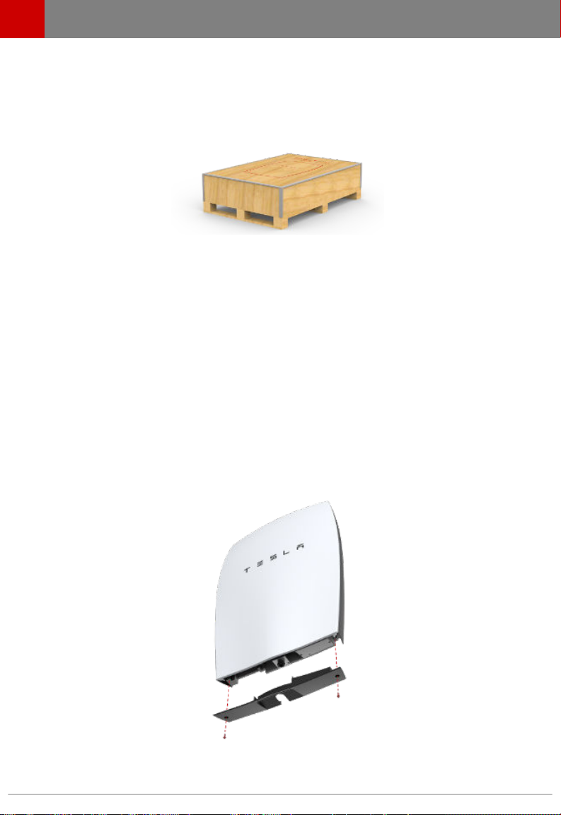
Warning: To protect Powerwall and its components from damage when transporting, handle
with care. Do not impact, pull, drag, or step on Powerwall. Do not subject Powerwall to any
strong force. To help prevent damage, leave Powerwall in its shipping packaging until it is
ready to be installed.
Warning: Do not insert foreign objects into any part of Powerwall.
Warning: Do not expose Powerwall or its components to direct flame.
Important Safety Instructions
2 Powerwall Installation Manual

Warning: Do not install Powerwall near heating equipment.
Warning: Do not immerse Powerwall or its components in water or other fluids.
Caution: Do not use cleaning solvents to clean Powerwall, or expose Powerwall to flammable
or harsh chemicals or vapors.
Caution: Do not use fluids, parts, or accessories other than those specified in this manual,
including use of non-genuine Tesla parts or accessories, or parts or accessories not purchased
directly from Tesla or a Tesla-certified party.
Caution: Do not place Powerwall in a storage condition for more than one (1) month, or
permit the electrical feed on the Powerwall to be severed for more than one (1) month,
without placing Powerwall into a storage condition in accordance with Tesla’s storage
specifications.
Caution: Do not paint any part of Powerwall, including any internal or external components
such as the exterior shell or casing.
Caution: Do not connect Powerwall directly to photovoltaic (PV) solar wiring.
Caution: When installing Powerwall in a garage or near vehicles, keep it out of the driving
path. If possible, install the Powerwall on a side wall and/or above the height of vehicle
bumpers.
Caution: Powerwall has a pre-installed aesthetic front cover. To prevent damage, keep
Powerwall flat on its back until just before lifting Powerwall onto the wall mount bracket.
ENVIRONMENTAL CONDITIONS
Warning: Install Powerwall at a height that prevents damage from flooding.
Warning: Operating or storing Powerwall in temperatures outside its specified range might
cause damage to Powerwall.
Warning: Do not expose the Powerwall to ambient temperatures above 60°C (140°F) or
below -30°C (-22°F).
Caution: Ensure that no water sources are above or near Powerwall, including downspouts,
sprinklers, or faucets.
Caution: Ensure that snow does not accumulate on top of or around Powerwall.
Important Safety Instructions
Tesla Energy 3

ELECTRICAL SPECIFICATIONS
Charge and Discharge Power, Peak and
Continuous
3.3 kW
Energy16.4 kWh
DC Voltage 350 V to 450 V
DC Current, Maximum and Continuous 9.5 A
Round Trip DC Eciency (Beginning of Life)192.5%
ENVIRONMENTAL SPECIFICATIONS
Operating Temperature2-20 °C to 50 °C (-4 °F to 122 °F)
Humidity <95% non-condensing
Storage <=12 months State of Energy (SoE): 25% initial
Noise (at Full Thermal System
Performance)
<49 dBA front, and <55 dBA top, at a distance of 1m
Maximum Altitude 3000 m (9843 ft)
Ingress Rating IP35 and NEMA 3R (Powerwall)
IP67 (battery Pod only)
Impact Rating IK09
Seismic Rating AC156 and IEEE 693-2005
MECHANICAL SPECIFICATIONS
Length
Width
Depth
1302 mm (51.3 in)
862 mm (34 in)
183 mm (7.2 in)
Weight 97 kg (214 lbs)
1Values provided for 25 °C, 2 kW charge/discharge power, 400 V to 450 V DC bus.
2Performance might be de-rated in extreme ambient temperatures.
Specifications
4 Powerwall Installation Manual

PHYSICAL REQUIREMENTS
Powerwall must be installed on an upright wall that can support 115 kg (254 lbs), the maximum
weight of Powerwall and its installation packaging. The wall must be flush and extend to all edges
of the system, allowing no access to the back of the unit once it is mounted. Do not mount
Powerwall horizontally or upside down. Do not mount Powerwall on a wall that is tilted backward
or forward more than 5 degrees.
Powerwall requires adequate clearance for installation, cabling, and airflow. Do not mount any
other objects within the clearance space illustrated below, except those explicitly required by the
installation (for example, conduit or DC disconnect depending on local installation codes). Do not
install anything between Powerwall and the ceiling.
Note: Powerwall has a pump and fan that produce a gentle hum during operation, comparable to
a typical refrigerator or dishwasher. This intermittent noise is normal and enables Powerwall to
maintain ideal battery temperature. The noise level depends on the ambient temperature and the
power level of operation. Choose the installation location of the Powerwall with due consideration
for the owner's sensitivity to noise level.
TEMPERATURE REQUIREMENTS
Powerwall is capable of charging and discharging within the full ambient temperature range listed
in the Specifications section. At the high and low ends of the temperature range, Powerwall may
limit charge or discharge power based on battery cell temperature to improve battery lifespan.
Installation in full sun raises the temperature inside the enclosure above ambient temperature. This
temperature rise is not a safety risk, but can impact the performance of the batteries. Installation
in full sun is not recommended to optimize the use of Powerwall.
Do not install Powerwall in a room with sustained elevated temperatures, such as a boiler room.
The average ambient temperature over the system's life should be 30°C (86 °F) or less.
INSTALLATION REQUIREMENTS
Powerwall must be installed with a compatible inverter. Wiring and conduit (where necessary)
must be provided by the installer.
DC disconnect requirements between Powerwall and the inverter are subject to local codes.
Ensure that the installation meets local DC disconnect requirements. Check the inverter
installation manual to understand site connections and overcurrent protection.
Site Requirements
Tesla Energy 5

All U.S. and Canada electrical installations must be done in accordance with local codes and the
National Electric Code (NEC) ANSI/NFPA 70 or the Canadian Electrical Code CSA C22.1.
All installations must conform to the laws, regulations, codes, and standards applicable in the
jurisdiction of installation.
MINIMUM SPACE REQUIREMENTS
Total ceiling height
Clearance above
Clearance below
2000 mm (6.5 ft )
300 mm (1 ft)
300 mm (1 ft)
Lateral wall space
Clearance from each side
1070 mm (42 in)
100 mm (4 in)
Depth of workspace3762 mm (30 in)
3Depth requirement is typically determined by working clearances required in the local
installation code.
Site Requirements
6 Powerwall Installation Manual

Warning: Powerwall must be installed by a Tesla Energy Certified Installer.
STEP 1 - REMOVE THE LID AND BOTTOM COVER
STEP 2 - REMOVE THE SPLASH COVER
STEP 3 - SET THE COMMUNICATION SWITCHES
STEP 4 - SET THE ADDRESS SWITCHES
STEP 5 - PREPARE THE WIRING
STEP 6 - CONNECT THE WIRING
STEP 7 - ATTACH THE SPLASH COVER
STEP 8 - REMOVE THE PALLET
STEP 9 - DETERMINE THE MOUNTING LOCATION FOR POWERWALL
STEP 10 - INSTALL THE WALL MOUNT BRACKET
STEP 11 - MOUNT POWERWALL
STEP 12 - REMOVE THE PACKAGING
STEP 13 - FEED WIRES THROUGH THE CONDUIT PLATE OR CABLE GLAND
STEP 14 - CONNECT MULTIPLE POWERWALLS TOGETHER
STEP 15 - CONNECT POWERWALL TO THE INVERTER
STEP 16 - ATTACH THE SIDE COVERS
STEP 17 - ATTACH THE BOTTOM COVER
STEP 18 - REPACK THE SHIPPING BOX
REQUIRED TOOLS
• Wall mount bracket fasteners
Note: The details below are only guidance and are not guaranteed to be applicable. Consult
local building codes and a structural engineer to ensure the use of appropriate fasteners.
• Minimum of 6 fasteners, stainless steel, diameter 10 mm (3/8 in)
• Fastener head clearance for all positions but two bottom outer holes: 18 mm (11/16 in)
• Fastener head clearance for bottom two holes at 600 mm (24 in) spacing: 8 mm (5/16 in)
• Washers between fastener heads and wall mount bracket are recommended
• Drill and a drill bit suitable for drilling pilot holes in the desired mounting surface
• Socket wrench
• 10 mm socket adapter (for covers and wall mount bracket side tabs)
• 17 mm socket adapter (for wood block bolts)
• Large flathead screwdriver (for ground lug)
• Optional: small flathead screwdriver (for wiring terminal tabs)
• T20 Torx (for splash cover and screws fastening box to wood blocks)
• T30 Torx (for packaging L-bracket and conduit/gland plate)
• Torque wrench
• Stud finder (for wood installations)
• Level tool
• Painter's tape and/or pencil
• Wire stripper and wiring (as described in Step 5)
• Conduit fitting or cable gland (as appropriate)
• Lift tool or adequate personnel trained and capable of lifting 115 kg (254 lb) from ground level
to approximately chest height
Warning: Powerwall is heavy and challenging to lift. Lift equipment is recommended.
To prevent injury, wear work boots (preferably steel-toed), long pants, and gloves.
Step-by-Step Installation Instructions
Tesla Energy 7

STEP 1 - REMOVE THE LID AND BOTTOM COVER
For easiest installation, pre-install wiring and set all switches while Powerwall is still on its pallet,
as described below.
1. Lay the box flat on the ground with the pallet side down.
2. Use a T20 Torx to remove 8 screws from each box side. Do not remove the screws near the
corners of the box.
3. Lift the box lid and set it aside.
4. Verify that the box contains the following items:
• Powerwall
• Wall mount bracket on the pallet under the unit (wall mounting fasteners are not
included)
• Two side covers
• Two M6, 10 mm external hex bolts for the wall mount bracket side tabs (plus one spare
bolt for side tabs or bottom cover)
• Spare M4, T20 bolt (if needed for splash cover)
If any parts are damaged or missing, contact the Tesla Energy Authorized Reseller or Tesla
Energy Certified Installer. If any damage is detected, address high voltage and other safety
risks immediately. Do not continue the installation procedure.
5. Use a 10 mm hex socket to remove a 10 mm external hex M6 screw on each side of the bottom
cover.
6. Carefully slide o the bottom cover, ensuring that nothing is caught or bent.
7. Set the bottom cover and the 2 screws aside for reassembly after the wiring is complete.
Step-by-Step Installation Instructions
8 Powerwall Installation Manual

STEP 2 - REMOVE THE SPLASH COVER
Warning: Before beginning the wiring portion of the installation, verify that the inverter is
powered o.
Note: When the splash cover is removed, an Enable circuit disables the internal electronics of
Powerwall. Refer to the illustration in Step 5 for the location of the Enable buttons.
Warning: Ensure the Enable buttons are not pressed by any wiring.
Warning: The Enable buttons only disable power from Powerwall. They do not disable power
from the inverter.
1. Turn o power to the relevant area at the circuit breaker panel.
2. Turn o the inverter.
3. Open the DC disconnect switch (if applicable for the installation).
4. Use a multimeter to verify that the wires from the inverter to Powerwall are not live.
5. Use a T20 Torx driver to remove the two splash cover screws.
6. Carefully remove the splash cover. Ensure that nothing is caught or bent. Set the screws and
cover aside for reassembly after the wiring is complete.
Warning: Use a multimeter to ensure no voltage is present on the terminals of the
Powerwall circuit board.
7. Before fitting any wires, practice removing and re-fitting the splash cover. Keep the whole
cover square to the unit as it is aligned with the mounting holes. Do not push in one side
before the other.
Step-by-Step Installation Instructions
Tesla Energy 9

STEP 3 - SET THE COMMUNICATION SWITCHES
Communication switches are located on the lower right side of the board.
1. Refer to the inverter manual to determine:
• Whether to use CAN or Modbus communication
• Whether bias is required (if the system is using Modbus)
2. Set the CAN-Modbus switch:
Inverter Protocol Switch Position
SMA CAN Left
SolarEdge Modbus (RS485) Right
3. Set the termination switch based on whether the installation is one unit or multiple units, and
whether the system requires Modbus bias, per the table below.
Inverter and Unit Position Termination Switch Position
SMA Termination, NO Modbus bias Top
SolarEdge, multi-unit other than the
last
No termination Middle
SolarEdge, single or last unit Termination WITH Modbus bias Bottom
Step-by-Step Installation Instructions
10 Powerwall Installation Manual

STEP 4 - SET THE ADDRESS SWITCHES
The DIP switch block has three white pins numbered “1”, “2”, and “3” from top to bottom with a
value of ‘1’ to the left and ‘0’ to the right. Use these switches to set the Powerwall address.
Set the switches according to each Powerwall's position, per the table below. Set a single
Powerwall using Powerwall 0 settings.
Note: Always check with the inverter partner for inverter abilities and instructions before
connecting multiple Powerwalls.
Address Switches Powerwall 0 Powerwall 1
Switch 1 Right Left
Switch 2 Right Right
Switch 3 Right Right
These switch settings create the addresses below for each unit.
Protocol Powerwall 0 Address Powerwall 1 Address
Modbus 24 25
CAN 80 81
Step-by-Step Installation Instructions
Tesla Energy 11

STEP 5 - PREPARE THE WIRING
Refer to local building and electrical codes when selecting appropriate wire gauge and length. Cut
the ends of the wires to have clean, even ends. Strip the ends of the wires enough to make solid
contact in the connector, while ensuring that no bare wire extends beyond the connector edge.
To ensure that installation is as simple as possible, select flexible wires with the smallest overall
approved diameter. The wiring compartment is relatively small and the use of small diameter wires
significantly speeds and simplifies the installation process.
A single 12 V power connection is required to power the logic. The Logic 12 V might be called
"Logic," "Always On," "Communication," or similar.
Caution: Do not splice wiring inside Powerwall.
Caution: Do not add extra wiring to the left of the conduit or gland entry. Additional wiring
may interfere with water ingress and high voltage shielding to the pump.
Note: Use shielded twisted pair communication wire and ground the shielding at one end. This
reduces the possibility of noise on the communication cable. Do not ground the shield at both
ends, which would create a ground loop.
Note: The 450 VDC cable is run in close proximity to the low voltage and communication cabling.
Therefore, ensure that all cables to Powerwall are:
• Wet or oil rated
• At least 600 V insulation class
If low voltage and communication wires do not already meet these requirements, 600V insulation
class heat shrink can be added around the bundle during installation.
Step-by-Step Installation Instructions
12 Powerwall Installation Manual

Wire Type Port Label Wire Gauge Strip Length
1 Ground/earth 2.5-6 mm2(14-10
AWG), 60 °C
8 to 12 mm
2 DC power +
DC power -
+ tab
- tab
2.5-6 mm2(14-10
AWG), 60 °C
12 to 16 mm
3 Enable line ENABLE 0.2-1 mm2(24-18
AWG), 60 °C
7 to 9 mm
4 Logic power
Logic return
LOGIC+
LOGIC-
0.2-1 mm2(24-18
AWG), 60 °C
7 to 9 mm
5 Negative communication
Positive communication
COM HI
COM LO
0.2-1 mm2(24-18
AWG), 60 °C
7 to 9 mm
6 Enable buttons (disable power when splash cover is o)
7 Output connector for multiple units (J6)
8 Primary connector (J7)
9 Communication switches
10 Address switches
Note: Powerwall 1067000-00-C does not require separate wiring for thermal power.
Step-by-Step Installation Instructions
Tesla Energy 13

STEP 6 - CONNECT THE WIRING
Refer to the numbers on the previous wiring table and image. The plastic cover over the board has
raised printing on it that names each terminal.
1. Loosen the chassis ground screw terminal (1) with a flathead screwdriver.
2. Insert the ground/earth wire beneath the lug screw from the left side. Torque according to the
wire size:
• 2.5-5 mm2(14-12 AWG): 4.0 Nm (35 lbf-in)
• 6-8 mm2(10-8 AWG): 4.5 Nm (40 lbf-in)
3. Pull both high voltage locking tabs on the spring terminal (2) away from the board to open
them.
Note: New tabs can be dicult to close. Close and open each tab once without wires before
installation.
4. Route the positive (+) and negative (-) DC power wires behind the red and black internal DC
wires, and fully insert them into the spring terminal tabs. The left slot is Positive and the right
slot is Negative.
5. Close the locking tabs by pushing them up, so that the tab is flush with the connector. Close
tabs one at a time. Lightly tug on each of the HV wires to ensure it is secure. If any wire must
be removed, pull the locking tab open, then pull out the wire.
Step-by-Step Installation Instructions
14 Powerwall Installation Manual

Warning: Verify that both High Voltage tabs are locked completely shut over the wires
(the image shows the correct position). The tabs have an intermediate position that shuts
halfway, which is NOT electrically safe.
6. Route all data wires behind the red and black internal DC wires and in front of the field-
installed DC power wires, toward the J7 connector. Insert each J7 wire (3, 4, 5) into its port as
described in the wiring table above. If any J7 wire must be removed, gently push down on the
appropriate button with a small screwdriver, then pull the wire out.
7. Lightly tug on every field-installed wire separately, to ensure it is seated properly.
8. Verify that the polarities of all power and communication cables are correct.
All wires are now connected, leaving the communication connector (J6) on the left unused. If
installing multiple Powerwalls, communication wires can be daisy-chained as described in Step 14.
Step-by-Step Installation Instructions
Tesla Energy 15

STEP 7 - ATTACH THE SPLASH COVER
1. Route all wires toward the top left of the circuit board to keep them away from the Enable
buttons. When the splash cover is removed, the Enable buttons disable power to the unit for
service.
Warning: Misrouted wiring that keeps the buttons pressed in when the cover is o can
create a risk of electric shock. Ensure that the Enable buttons are not pressed by any
wiring.
2. Route all field-installed wires into the channel to the left of the splash cover mounting hole.
3. Align the splash cover with the circuit board.
4. Ensure that all wires route out of the splash cover through its side opening, and that wires are
not pinched or kinked.
5. Ensure that the Enable buttons are pressed when the cover is attached. Listen for the click of
the buttons being pressed.
6. Use a T20 Torx driver to attach the splash cover with two M4 screws. Torque to 3 Nm (27 in-
lbs).
7. Use the included “fir tree” zip tie (in the exterior shipping pouch with the manual) to secure all
field wires to the existing hole in the metal bracket. If the fir tree zip tie is already installed
around the internal factory wiring, use a second zip tie to secure the field wiring to the
internal wiring harness in the same location.
Caution: To ensure that wires do not interfere with fitting the splash cover or bottom
cover, both factory wires and field wires must follow the route shown in images and be
fastened in place with zip ties. Improper cover installation can nullify the ingress rating for
Powerwall.
Step-by-Step Installation Instructions
16 Powerwall Installation Manual

STEP 8 - REMOVE THE PALLET
Caution: Reinstall the front cover of the box for structural stability while lifting.
Note: Two people are needed for this procedure.
1. Place the box lid carefully back over Powerwall and move it sideways until the inside of the
box lid touches the top edge of Powerwall. This leaves room for the bottom of the box to flex
without damaging Powerwall's bottom cover.
2. Align the lower edge of the box between the upper and lower wood blocks on the sides of the
Powerwall.
3. Use a T20 Torx to securely reinstall 2 screws into each of the 4 upper blocks attached to the
sides of the Powerwall (8 screws total). Now the Powerwall is secured to the sides of the box
with the top blocks, and the bottom blocks remain with the pallet.
4. Tuck all wiring into the box lid to avoid pinching or pulling the wires.
5. With one hand on the front cover and one hand under the pallet towards the top corner, both
installers carefully tilt the box up onto its bottom end so that the Powerwall is standing right
side up. Ensure the box is in a stable location, such as against a wall, where it will not be
bumped or tip over.
Caution: Never leave a Powerwall unattended while it is in a standing position.
Step-by-Step Installation Instructions
Tesla Energy 17

6. Remove the pallet. The mounting cleat on the back of Powerwall should now be visible, and
extend past the edge of the box for easy installation.
7. Remove the wall mount bracket from the inside face of the pallet.
Step-by-Step Installation Instructions
18 Powerwall Installation Manual
Other manuals for Powerwall
4
Table of contents
Other Tesla Batteries Charger manuals

Tesla
Tesla 1069742-00-A User manual

Tesla
Tesla TI150 Series User manual

Tesla
Tesla TI45014D User manual

Tesla
Tesla WALL CONNECTOR User manual

Tesla
Tesla QC50 User manual

Tesla
Tesla WC1 User manual

Tesla
Tesla WALL CONNECTOR User manual

Tesla
Tesla Powerwall User manual

Tesla
Tesla Gen 3 Wall Connector User manual

Tesla
Tesla Wall Connector Gen 3 User manual
Popular Batteries Charger manuals by other brands

Parkside
Parkside PAP 20 A1 Translation of the original instructions

Leviton
Leviton Evr-Green EVC11-300 user guide

GreenWorks Pro
GreenWorks Pro Ultapower 60V CAC801 Operator's manual

MIR
MIR MiRCharge 24V operating guide

Sentry
Sentry Voyager Series Installation & operation

MyCharge
MyCharge RAPID RECHARGE quick start guide