Tesla Powerwall User manual

POWERWALL
INSTALLATION AND USER’S MANUAL

©2015 TESLA MOTORS, INC. All rights reserved.
All information in this document is subject to copyright and other intellectual property rights of Tesla Motors, Inc.
and its licensors. This material may not be modified, reproduced or copied, in whole or in part, without the prior
written permission of Tesla Motors, Inc. and its licensors. Additional information is available upon request. The
following are trademarks or registered trademarks of Tesla Motors, Inc. in the United States and other countries:
All other trademarks contained in this document are the property of their respective owners and their use herein
does not imply sponsorship or endorsement of their products or services. The unauthorized use of any trademark
displayed in this document or on the product is strictly prohibited.
TESLA TESLA MOTORS POWERWALL
For the latest Powerwall documents in all supported
languages, including the Warranty, go to:
www.teslamotors.com/support/powerwall
To secure the full 10-year product warranty, be sure to
register Powerwall online.
Warning: Read this entire document before installing or
using Powerwall. Failure to do so or to follow any of the
instructions or warnings in this document can result in
electrical shock, serious injury, or death, or can damage
Powerwall, potentially rendering it inoperable.
PRODUCT SPECIFICATIONS
All specifications and descriptions contained in this document are verified to be accurate at
the time of printing. However, because continuous improvement is a goal at Tesla, we reserve
the right to make product modifications at any time.
The images provided in this document are for demonstration purposes only. Depending on
product version and market region, details may appear slightly different.
ERRORS OR OMISSIONS
To communicate any inaccuracies or omissions in this manual, please send an email to:
ELECTRONIC DEVICE: DO NOT THROW AWAY
Proper disposal of batteries is required. Refer to your local codes for disposal
requirements.
MADE IN THE USA

Important Safety Instructions............................................................................. 3
SYMBOLS IN THIS DOCUMENT..................................................................................................................................... 3
GENERAL INFORMATION................................................................................................................................................ 3
ENVIRONMENTAL CONDITIONS.................................................................................................................................. 4
QUALIFIED INSTALLERS..................................................................................................................................................4
What is Powerwall?................................................................................................. 5
Specifications............................................................................................................ 6
ELECTRICAL SPECIFICATIONS..................................................................................................................................... 6
ENVIRONMENTAL SPECIFICATIONS...........................................................................................................................6
MECHANICAL SPECIFICATIONS................................................................................................................................... 6
Site Requirements....................................................................................................7
PHYSICAL REQUIREMENTS............................................................................................................................................ 7
NON-PHYSICAL REQUIREMENTS.................................................................................................................................7
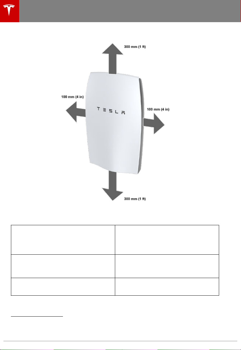
MINIMUM SPACE REQUIREMENTS...............................................................................................................................8
Step-by-Step Installation Instructions............................................................. 9
REQUIRED TOOLS.............................................................................................................................................................. 9
STEP 1 - REMOVE THE PALLET....................................................................................................................................10
STEP 2 - DETERMINE THE MOUNTING LOCATION FOR POWERWALL......................................................12
STEP 3 - INSTALL THE WALL MOUNT BRACKET.................................................................................................13
STEP 4 - MOUNT POWERWALL.................................................................................................................................. 14
STEP 5 - REMOVE THE PACKAGING..........................................................................................................................15
STEP 6 - REMOVE THE BOTTOM COVER................................................................................................................ 16
STEP 7 - REMOVE THE SPLASH COVER.................................................................................................................. 17
STEP 8 - SET THE COMMUNICATION SWITCHES.................................................................................................18
STEP 9 - SET THE ADDRESS SWITCHES................................................................................................................. 19
STEP 10 - PREPARE THE WIRING.............................................................................................................................. 20
STEP 11 - FEED WIRES THROUGH THE CONDUIT PLATE OR CABLE GLAND........................................ 22
STEP 12 - CONNECT THE WIRING..............................................................................................................................23
STEP 13 - CONNECT MULTIPLE POWERWALLS TOGETHER..........................................................................24
STEP 14 - CONNECT POWERWALL TO THE INVERTER...................................................................................24
STEP 15 - ATTACH THE SIDE COVERS......................................................................................................................25
STEP 16 - ATTACH THE SPLASH COVER.................................................................................................................26
STEP 17 - ATTACH THE BOTTOM COVER................................................................................................................26
STEP 18 - REPACK THE SHIPPING BOX................................................................................................................... 26
Operation and Care.............................................................................................. 27
NORMAL OPERATION.....................................................................................................................................................27
UNINTENDED OPERATION........................................................................................................................................... 27
POWERWALL CARE........................................................................................................................................................ 27
Contents

SAVE THESE IMPORTANT SAFETY INSTRUCTIONS. These installation and repair instructions
assume knowledge of high voltage electricity and should only be executed by Tesla Energy
Certified Installers. Tesla Motors assumes no liability for injury or property damage due to repairs
attempted by unqualified individuals or a failure to properly follow these instructions. These
warnings and cautions must be followed when using Powerwall.
SYMBOLS IN THIS DOCUMENT
This manual uses the following symbols to highlight important information:
Warning: WARNING indicates a hazardous situation which, if not
avoided, could result in injury or death.
Caution: CAUTION indicates a hazardous situation which, if not
avoided, could result in damage to the equipment.
Note: NOTE indicates an important step or tip that leads to best
results, but is not safety or damage related.
GENERAL INFORMATION
Warning: Read this entire document before installing or using Powerwall. Failure to do so or
to follow any of the instructions or warnings in this document can result in electrical shock,
serious injury, or death, or can damage Powerwall, potentially rendering it inoperable.
Warning: A battery can present a risk of electrical shock, fire, or explosion from vented gases.
Observe proper precautions.
Warning: Use Powerwall only with a Tesla-approved inverter.
Warning: Use Powerwall only as directed.
Warning: Do not use Powerwall if it is defective, appears cracked, broken, or otherwise
damaged, or fails to operate.
Warning: Before beginning the wiring portion of the installation, verify that the inverter is
powered o.
Warning: Do not attempt to open, disassemble, repair, tamper with, or modify Powerwall.
Powerwall is not user serviceable. Batteries in Powerwall are not replaceable. Contact the
Tesla Energy Authorized Reseller who sold the Powerwall for any repairs.
Warning: Do not connect Powerwall to alternating current carrying conductors. Powerwall
must be wired to either an inverter or a DC combiner panel that is then wired to an inverter.
No other wiring configuration may be used.
Warning: Powerwall contains components, such as switches and relays, that can produce arcs
or sparks.
Warning: To protect Powerwall and its components from damage when transporting, handle
with care. Do not impact, pull, drag, or step on Powerwall. Do not subject Powerwall to any
strong force. To help prevent damage, leave Powerwall in its shipping packaging until it is
ready to be installed.
Warning: Do not insert foreign objects into any part of Powerwall.
Warning: Do not expose Powerwall or its components to direct flame.
Warning: Do not immerse Powerwall or its components in water or other fluids.
Important Safety Instructions
Important Safety Instructions 3

Caution: Do not use cleaning solvents to clean Powerwall, or expose Powerwall to flammable
or harsh chemicals or vapors.
Caution: Do not use fluids, parts, or accessories other than those specified in this manual,
including use of non-genuine Tesla parts or accessories, or parts or accessories not purchased
directly from Tesla or a Tesla-certified party.
Caution: Do not place Powerwall in a storage condition for more than one (1) month, or
permit the electrical feed on the Powerwall to be severed for more than one (1) month,
without placing Powerwall into a storage condition in accordance with Tesla’s storage
specifications.
Caution: Do not paint any part of Powerwall, including any internal or external components
such as the exterior shell or casing.
Caution: Do not connect Powerwall directly to photovoltaic (PV) solar wiring.
ENVIRONMENTAL CONDITIONS
Warning: Install Powerwall at a height that prevents damage from flooding.
Warning: When used in an indoor location such as a garage, Powerwall must be located at
least 15 cm (6 in) above the floor.
Warning: Operating or storing Powerwall in temperatures outside its specified range might
cause damage to Powerwall.
Warning: Do not expose the Powerwall to ambient temperatures above 60°C (140°F) or
below -30°C (-22°F).
Caution: Ensure that no water sources are above or near Powerwall, including downspouts,
sprinklers, or faucets.
Caution: Ensure that snow does not accumulate on top of or around Powerwall.
QUALIFIED INSTALLERS
Warning: Powerwall installation must be carried out only by Tesla Energy Certified Installers,
who have been trained in dealing with high voltage electricity.
Warning: Powerwall is heavy and challenging to lift.
Important Safety Instructions
4

THE FUTURE OF SUSTAINABLE ENERGY
Powerwall is a lithium-ion battery system that turns solar panels into an all-day resource while
oering backup power in the event of a grid outage. Powerwall enables storage of renewable
energy, allowing optimized home energy control and an increasing amount of total electricity
production to come from renewable sources. Reliable renewable energy improves the resiliency of
the grid, reduces energy costs, and increases the impact of electric vehicle ownership.
POWER WHEN NEEDED
Powerwall enables the storage of energy from solar panels during the day, or from the grid when
energy rates are low; discharges energy for backup or use at night; and automatically optimizes
home energy. Powerall thereby maximizes solar consumption and reduces energy spending.
A FLEXIBLE SOLUTION
Powerwall is available in a weekly cycling version and a daily cycling version. Powerwall can be
charged from solar or grid power and can provide backup power. If greater amounts of energy are
needed, multiple Powerwalls can be installed together to work as a larger system.
Note: To secure the full 10-year product warranty, be sure to register Powerwall online.
What is Powerwall?
What is Powerwall? 5

ELECTRICAL SPECIFICATIONS
Daily Version Weekly Version
Power
Discharge, Continuous
Discharge, Peak
Charge, Continuous
3.3 kW
3.3 kW
3.3 kW
5.0 kW
7.0 kW (10 sec)
3.3 kW
Energy 6.4 kWh 9.1 kWh
9.8 kWh (o-grid mode)
DC Voltage 350 V to 450 V
Maximum DC Current
Continuous DC Current
9.5 A
9.5 A
20 A
14.3 A
Round Trip DC Eciency
(Beginning of Life)1
92.5% 93%
ENVIRONMENTAL SPECIFICATIONS
Operating Temperature2-20 °C to 50 °C (-4 °F to 122 °F)
Humidity <95% condensing
Storage Conditions
<24 hours
<1 month
<12 months
-30 °C to 60 °C (-22 °F to 140 °F)
-20 °C to 45 °C (-4 °F to 113 °F)
-20 °C to 30 °C (-4 °F to 86 °F), State of Energy (SoE):
50% initial
Maximum Altitude 3000 m (9843 ft)
Ingress Rating IP35 & NEMA 3R (Powerwall)
IP67 (battery Pod only)
Impact Rating IK09
MECHANICAL SPECIFICATIONS
Dimensions
Length
Width
Depth
1302 mm (51.3 in)
862 mm (34 in)
183 mm (7.2 in)
Weight Daily: 95 kg (210 lbs) Weekly: 101 kg (223 lbs)
1Values provided for 25 °C, 2 kW charge/discharge power, 400 V to 450 V DC bus.
2Performance might be de-rated in extreme ambient temperatures.
Specifications
6

PHYSICAL REQUIREMENTS
Caution: Ensure that no water sources are above or near Powerwall, including downspouts,
sprinklers, or faucets.
Caution: Ensure that snow does not accumulate on top of or around Powerwall.
Caution: When installing Powerwall in a garage or near vehicles, keep it out of the driving
path. If possible, install the Powerwall on a side wall and/or above the height of vehicle
bumpers.
Caution: Powerwall has a pre-installed aesthetic front cover. To prevent damage, keep
Powerwall flat on its back until just before lifting Powerwall onto the wall mount bracket.
Powerwall must be installed on upright walls that can support 115 kg (254 lbs), the maximum
weight of Powerwall and its installation packaging. Do not mount Powerwall horizontally or upside
down. Do not mount Powerwall on a wall that is tilted backward or forward more than 5 degrees.
Powerwall requires adequate clearance for installation, cabling, and airflow. Do not mount any
other objects within the clearance space illustrated below, except those explicitly required by the
installation (for example, conduit or DC disconnect depending on local installation codes). Do not
install anything between Powerwall and the ceiling.
Powerwall is capable of charging and discharging within the full ambient temperature range listed
in the Specifications section. At the high and low ends of the temperature range, Powerwall may
limit charge or discharge power based on battery cell temperature to improve battery lifespan.
Installation in full sun raises the temperature inside the enclosure above ambient temperature. This
temperature rise is not a safety risk, but can impact the performance of the batteries. Installation
in full sun is not recommended to optimize the use of Powerwall.
Do not install Powerwall in a room with sustained elevated temperatures, such as a boiler room.
The average ambient temperature over the system's life should be 30°C (86 °F) or less.
NON-PHYSICAL REQUIREMENTS
Powerwall must be installed with a compatible inverter. Wiring and conduit (where necessary)
must be provided by the installer.
DC disconnect requirements between Powerwall and the inverter are subject to local codes.
Ensure that the installation meets local DC disconnect requirements. Check the inverter
installation manual to understand site connections and overcurrent protection.
All U.S. and Canada electrical installations must be done in accordance with local codes and the
National Electric Code (NEC) ANSI/NFPA 70 or the Canadian Electrical Code CSA C22.1.
All installations must conform to the laws, regulations, codes, and standards applicable in the
jurisdiction of installation.
Site Requirements
Site Requirements 7

MINIMUM SPACE REQUIREMENTS
Height
Total ceiling height
Clearance above
Clearance below
2000 mm (6.5 ft )
300 mm (1 ft)
300 mm (1 ft)
Lateral
Wall space
Clearance from each side
1070 mm (42 in)
100 mm (4 in)
Depth
Depth of workspace3153 mm (6 in)
3Depth requirement is typically determined by working clearances required in the local
installation code.
Site Requirements
8

Powerwall must be installed by a Tesla Energy Certified Installer.
STEP 1 - REMOVE THE PALLET
STEP 2 - DETERMINE THE MOUNTING LOCATION FOR POWERWALL
STEP 3 - INSTALL THE WALL MOUNT BRACKET
STEP 4 - MOUNT POWERWALL
STEP 5 - REMOVE THE PACKAGING
STEP 6 - REMOVE THE BOTTOM COVER
STEP 7 - REMOVE THE SPLASH COVER
STEP 8 - SET THE CONFIGURATION SWITCHES
STEP 9 - SET THE ADDRESS SWITCHES
STEP 10 - PREPARE THE WIRING
STEP 11 - FEED WIRES THROUGH THE CONDUIT PLATE OR CABLE GLAND
STEP 12 - CONNECT THE WIRING
STEP 13 - CONNECT MULTIPLE POWERWALLS TOGETHER
STEP 14 - CONNECT POWERWALL TO THE INVERTER
STEP 15 - ATTACH THE SIDE COVERS
STEP 16 - ATTACH THE SPLASH COVER
STEP 17 - ATTACH THE BOTTOM COVER
STEP 18 - REPACK THE SHIPPING BOX
REQUIRED TOOLS
• Wall mount bracket fasteners
Note: The details below are only guidance and are not guaranteed to be applicable. Consult
local building codes and a structural engineer to ensure the use of appropriate fasteners.
• Minimum of 6 fasteners, stainless steel, diameter 10 mm (3/8 in)
• Fastener head clearance for all positions but two bottom outer holes: 18 mm (11/16 in)
• Fastener head clearance for bottom two holes at 600 mm (24 in) spacing: 8 mm (5/16 in)
• Washers between fastener heads and wall mount bracket are recommended
• Drill and a drill bit suitable for drilling pilot holes in the desired mounting surface
• Socket wrench
• 10 mm socket adapter (for covers and wall mount bracket side tabs)
• 17 mm socket adapter (for wood block bolts)
• Large flathead screwdriver (for ground lug)
• Optional: small flathead screwdriver (for wiring terminal tabs)
• T20 Torx (for splash cover)
• T25 Torx (for screws fastening box to wood blocks)
• T30 Torx (for packaging L-bracket and conduit/gland plate)
• Torque wrench
• Stud finder (for wood installations)
• Level tool
• Painter's tape and/or pencil
• Wire stripper and wiring (as described in Step 10)
• Conduit fitting or cable gland (as appropriate)
• Lift tool or adequate personnel trained and capable of lifting 115 kg (254 lb) from ground level
to approximately chest height
Warning: Powerwall is heavy and challenging to lift. Lift equipment is recommended.
To prevent injury, wear work boots (preferably steel-toed), long pants, and gloves.
Step-by-Step Installation Instructions
Step-by-Step Installation Instructions 9

STEP 1 - REMOVE THE PALLET
Caution: Leave the front cover of the box ON for structural stability while lifting.
Note: Two people are needed for this procedure.
1. Lay the box flat on the ground with the pallet side down.
2. Cut and remove the shipping straps around the box.
3. Use a T25 Torx to remove 2 screws from each of the 8 blocks on the box sides (shown in the
next image). Do not remove the screws near the corners of the box.
4. With the front cover still on, lift up the sides of the box and move it sideways until the top of
the box touches Powerwall inside. This leaves room for the bottom of the box to flex without
damaging Powerwall's bottom cover.
5. Align the lower edge of the box between the upper and lower wood blocks on the sides of the
Powerwall.
6. Use a T25 Torx to securely attach the same 2 screws into each of the 4 upper blocks attached
to the sides of the Powerwall. Now the Powerwall is secured to the sides of the box with the
top blocks, and the bottom blocks remain with the pallet.
7. With one hand on the front cover and one hand under the pallet towards the top corner, both
installers carefully tilt the box up onto its bottom end so that the printed Powerwall image on
the package cover is standing right side up. Ensure the box is in a stable location, such as
against a wall, where it will not be bumped or tip over.
Step-by-Step Installation Instructions
10

8. Remove the pallet back. The mounting cleat on the back of Powerwall should now be visible,
and extend past the edge of the box for easy installation.
9. Verify that the box contains the following items:
• Powerwall
• Wall mount bracket (wall mounting fasteners are not included)
• Two side covers
• Two M6, 10 mm external hex bolts for the wall mount bracket side tabs (plus one spare
bolt for side tabs or bottom cover)
• Spare M4, T20 bolt (if needed for splash cover)
If any parts are damaged or missing, contact the Tesla Energy Authorized Reseller or Tesla
Energy Certified Installer. If any damage is detected, address high voltage and other safety
risks immediately. Do not continue the installation procedure.
10. Remove the wall mount bracket from its foam padding on the inside face of the pallet.
Step-by-Step Installation Instructions
Step-by-Step Installation Instructions 11

STEP 2 - DETERMINE THE MOUNTING LOCATION FOR POWERWALL
1. Using the wall mount bracket as a guide, measure the proposed location for Powerwall. The
bracket must be bolted into studs or a load-bearing wall, and allow clearance on all sides as
shown in Site Requirements.
2. If mounting into wood, use a stud finder to locate and temporarily mark the center of the
wooden studs. It is important to install each fastener as close to the middle of each stud as
possible.
3. Position the thicker part of the bracket at the top, so that the flat side is flush with the wall.
Use the bracket as a guide to mark the location of the holes on the wall. Space the holes 200,
300, 400, 500, or 600 mm (8, 12, 16, 20, or 24 in) apart.
Note: Use a level tool to ensure that the bracket is level.
Step-by-Step Installation Instructions
12

STEP 3 - INSTALL THE WALL MOUNT BRACKET
1. Drill the pilot holes to attach the wall mount bracket to the wall.
2. Install at least four washers and fasteners into the top part of the bracket and two washers
and fasteners into the bottom of the bracket. There must be at least one fastener in each of
the six mounting hole rows. Install the fasteners in the order shown in the numbered image.
3. Verify that the bracket is firmly attached to the wall.
4. For easier alignment while lifting, use tape or a pencil to mark the wall at the height of the
bracket lip on the outside edges of the intended mount point.
Step-by-Step Installation Instructions
Step-by-Step Installation Instructions 13

STEP 4 - MOUNT POWERWALL
1. With Powerwall still in its box, keeping it as level as possible, lift it so that the mounting cleat
is just above the lip on the wall mount bracket. Use the tape or pencil marks on the wall as
visual guides.
2. Lower Powerwall so that the cleat on the back of Powerwall fits securely over the lip on the
bracket.
3. Ensure that Powerwall is centered on the bracket. When properly centered, Powerwall sits
between the two protruding tabs on the bottom part of the bracket.
Step-by-Step Installation Instructions
14

STEP 5 - REMOVE THE PACKAGING
Note: Two people are needed for this procedure.
1. First person: Hold the box in place from the bottom edge, to prevent the box from slipping
and damaging Powerwall's front cover.
2. Second person: Use a T25 Torx to remove the 8 screws holding the box to the wooden blocks.
3. Being careful not to bump the box into the sides or edges of Powerwall's front cover, remove
the box and carefully set it aside.
Note: Leave the protective sticker on the Powerwall front cover until installation is complete.
4. Use a 17 mm socket to remove the 4 bolts that hold the wooden spacer blocks against the
sides of Powerwall. Remove all 4 wooden blocks.
5. Use a T30 Torx driver to remove the screws from the metal L-brackets and discard.
6. Use a 10 mm socket tool and the 2 provided M6 external hex bolts to secure Powerwall to the
lower tabs of the wall mount bracket. Torque to 7 Nm (62 in-lbs).
Step-by-Step Installation Instructions
Step-by-Step Installation Instructions 15

STEP 6 - REMOVE THE BOTTOM COVER
Warning: Before beginning the wiring portion of the installation, verify that the inverter is
powered o.
1. Use a 10 mm hex socket to remove a 10 mm external hex M6 screw on each side of the bottom
cover.
2. Carefully slide o the bottom cover, ensuring that nothing is caught or bent.
3. Set the bottom cover and the 2 screws aside for reassembly after the wiring is complete.
Step-by-Step Installation Instructions
16

STEP 7 - REMOVE THE SPLASH COVER
Note: When the splash cover is removed, an Enable circuit disables the internal electronics of
Powerwall. The Enable button is located at the bottom of the circuit board, near the HV power
connectors.
Warning: Ensure the Enable button is not pressed by any wiring.
Warning: The Enable button only disables power from Powerwall. It does not disable power
from the inverter.
1. Turn o power to the relevant areas of the building at the circuit breaker panel.
2. Turn o the inverter.
3. Open the DC disconnect switch (if applicable for the installation).
4. Use a multimeter to verify that the wires from the inverter to Powerwall are not live.
5. Use a T20 Torx driver to remove the two splash cover screws.
6. Carefully remove the splash cover. Ensure that nothing is caught or bent. Set the screws and
cover aside for reassembly after the wiring is complete.
Warning: Use a multimeter to ensure no voltage is present on the terminals of the Powerwall
circuit board.
Step-by-Step Installation Instructions
Step-by-Step Installation Instructions 17

STEP 8 - SET THE COMMUNICATION SWITCHES
Communication switches are located on the lower right side of the board, next to the
communication connectors. The switches are independent and are labeled on the board:
1. Refer to the inverter manual to determine whether to use CAN or Modbus communication.
2. Set the switches based on whether the installation is one unit or multi-unit. A single
Powerwall, or the last Powerwall in a multi-unit chain, has one setting. All other Powerwalls in
a multi-unit chain have a second setting.
Switch Number Single/Last Unit,
CAN
Multi-unit, CAN Single/Last Unit,
Modbus
Multi-unit,
Modbus
S2 Right Right Left Left
S6 Right Right Left Left
S1 Up Up Down Down
S5 Down Up Down Down
S3 Down Down Down Down
S4 Up Up Up Down
Step-by-Step Installation Instructions
18
Other manuals for Powerwall
4
Table of contents
Other Tesla Batteries Charger manuals

Tesla
Tesla TI15014-120-240 User manual

Tesla
Tesla TI150 Series User manual

Tesla
Tesla Powerwall User manual

Tesla
Tesla WC4 User manual

Tesla
Tesla WC1 User manual

Tesla
Tesla WALL CONNECTOR User manual

Tesla
Tesla WALL CONNECTOR User manual

Tesla
Tesla Gen 3 Wall Connector User manual

Tesla
Tesla Wall Connector Gen 3 User manual

Tesla
Tesla QC50 User manual
Popular Batteries Charger manuals by other brands

G.T.Power
G.T.Power N802 instructions

Siemens
Siemens VersiCharge AC Installation and operation manual

KeyOuest
KeyOuest KO037478 quick start guide

DazeTechnology
DazeTechnology Dynamic Power Manager installation manual

VOLTCRAFT
VOLTCRAFT V-Charge Field 200 operating instructions

Eaton
Eaton xChargeIn Frequently asked questions