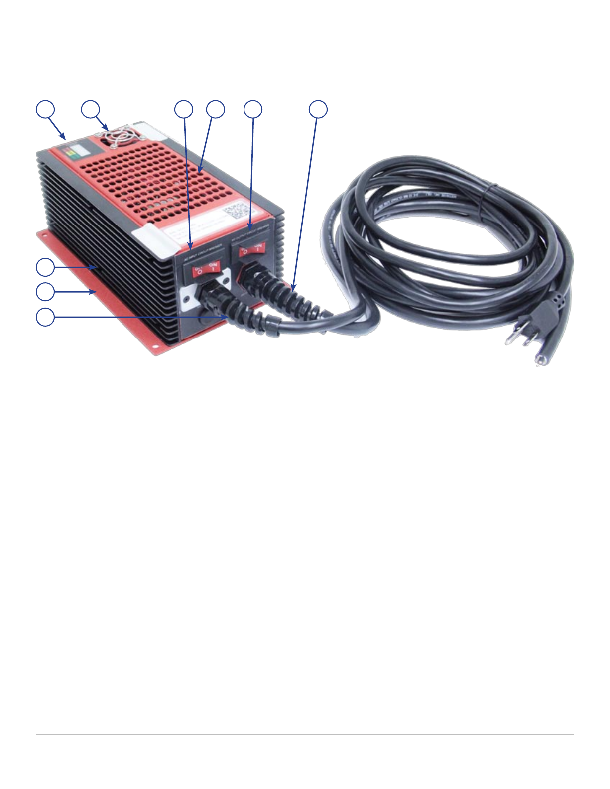
TI150 Series Hardwired Battery Charger/Conditioner 08-30-19
NOTE: All users must read this entire manual prior to operating
the TI150 Series Battery Charger/Conditioner.
The TI150 Battery Charger/Conditioner is a limited maintenance-free and sealed unit. No repairs are
authorized. Warranty will be voided if unit is tampered with in any way, or if unauthorized repairs are
made. For technical support please contact:
TESLA™ INDUSTRIES INCORPORATED
101 CENTERPOINT BLVD.
CENTERPOINT INDUSTRIAL PARK, NEW CASTLE, DELAWARE 19720
PHONE: (302) 324-8910 FAX: (302) 324-8912
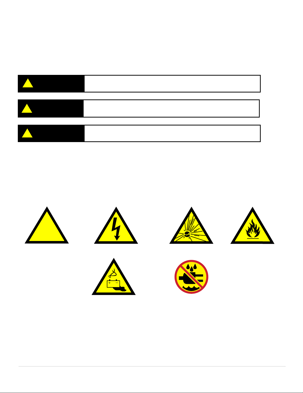
Shock Hazard Potential
CAUTION
Improper use or failure to follow instructions in this user manual can result in unit damage and/or injury or
death by electrical shock.
Any attempts to open or examine the inside of the unit via a tool or device (borescope, probe, etc.) can
result in unit failure and/or injury by electrical shock. This MPU is mainte nance free and should not be
opened or disassembled for any reason.
Always protect the unit from short circuit.
Shipping Hazards: The unit contains sealed, dry cell rechargeable batteries that do not pose a shipping
hazard.
All Ground Power Units, Micro Power Units (Aviation Batteries) and including, but not limited to, Battery Chargers/
Conditioners, manufactured by Tesla™ Industries, Inc., are able to safely and effectively charge any AGM, Lead
Acid battery.
The Tesla™ GPU’s and chargers are voltage and current regulated to 0.01% (dual loop). The charging voltage is
calibrated, by Tesla™, to 28.6 volts and is pure dc (no power line ripple).
Maximum Charge Voltage by Battery Type
Type: Charging Voltage / Cell Charging Voltage / 12v Charging Voltage / 24v
SLI/Flooded 2.366v to 2.416v 14.2v to 14.5v 28.4v to 29v
Lead Acid/Flooded 2.366v to 2.416v 14.2v to 14.5v 28.4v to 29v
Sealed Lead Acid 2.366v to 2.416v 14.2v to 14.5v 28.4v to 29v
VRLA 2.366v to 2.416v 14.2v to 14.5v 28.4v to 29v
AGM 2.433v to 2.466v 14.6v to 14.8v 29.2v to 29.6v
GEL 2.350v to 2.400v 14.1v to 14.4v 28.2v to 28.8v
Copyright © 2019 by Tesla™ Industries, Incorporated. All rights reserved.