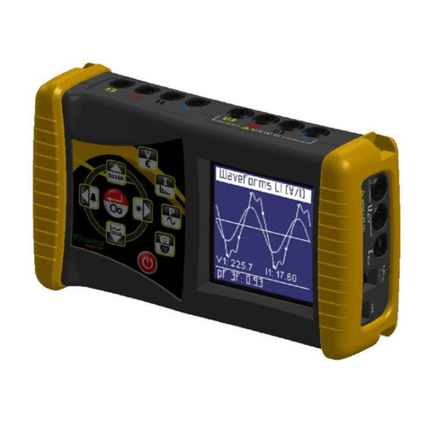
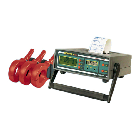
Elcontrol NanoVIP Plus Mem User manual

NANOVIP PLUS MEM
Supplemento al manuale di istruzione Nanovip Plus • Supplement to Nanovip Plus manual
• Supplement au manuel d’instruction Nanovip Plus • Ergänzung zum bedienungshandbuch
Nanovip Plus • Suplemento al manual de instrucciones Nanovip Plus
®
advanced technology for electrical installations

2120
NANOVIP PLUS MEM
SUPPLEMENTTO NANOVIP PLUS MANUAL
ENGLISH

23
The new functions on the NANOVIP PLUS MEM
with respect to the NANOVIP PLUS model are
the following:
a) Recording of campaigns of automatic measures
in an internal serial memory of 8 Megabits
(1 Mbyte)...........................................page 24
b) Addition and control of backlighting on display
LCD...................................................page 25
c) “Restore default” command of factory setup
parameters of the instrument............page 25
d) Display of the Active Power measure relative to
the harmonic selected.......................page 25
..............................................................
e) Downloading through serial line of the voltage
and current waveforms......................page 26
INDEX
f) Management of Harmonics Autoscroll.
..........................................................page 28
g) New Modbus command for setting a determined
Harmonic.. ........................................page 28
h) Input for external DC feeder (6VDC, 150 mA).
..........................................................page 29
Internal memory structure.......................page 34
Downloading data on measure campaigns stored
in internal memory...................................page 38
ENGLISH

25
B) DISPLAY BACKLIGHTING
The SETUP MENU is added with a Setup page on
display backlighting control with commands DISP
ON, DISP OFF and DISP AUT (automatic
backlighting for 10 seconds at each keystroke). The
life of the battery is about 45 hours with DISP ON
(the first five hours of which with backlighting on
and the following 40 hours with backlighting off) and
approximately double with DISP OFF.
C) RESTORE DEFAULT SETUP PARAMETERS
The SETUP MENU includes the possibility to restore
the default settings by using a command (TV ratio,
TA ratio, Configuration setup, Harmonics setup,
COM Setup).
D) DISPLAY OF ACTIVE POWER MEASURE OF
SELECTED HARMONIC
In the page displaying the RMS values relative to
the harmonic selected, there is now the possibility
to see the Active Power value (besides the values
of V, I and Power Factor) by keeping the Sel key
pressed.
24
This function allows you to store in a special flash-
type auxiliary memory (1024Kbyte) the entire range
of measures managed by NANOVIP PLUS, with a
maximum of 4032 recorded blocks of measures at
intervals from 2 second to 1...99 minutes.
The campaigns are recorded through the menu.
The SETUP MENU allows access to 4 pages for
setting data recording functions:
• Date setup
• Time setup (date and time are included at the top
of every record)
• Setup of the time interval between two recordings
(every 2 seconds, or at intervals of 1...99 minutes)
• Deletion of recorded data.
In the LOG CTRL MENU the recording of the
measure campaigns can be activated or deactivated;
this menu also displays the percentage recorded in
memory and the programmed rate of recording.
Once activated, the data LOG continues until it is
either deactivated or the memory is full: during this
time the part of the Setup menu relative to the LOG
(see the block diagram on the menu pages) is
deactivated; if the device is turned off and then
turned on again recording starts again.
In the MEAS PAGE two more pages are included
with display of the date and time.
To download data by serial line, see the dedicated
section.
A) RECORDING OF MEASURE CAMPAIGNS
(operation)
ENGLISH

2726
D13= lsb zero corresponding to samplings of second frame (Current)
D14= msb zero corresponding to samplings of second frame (Current)
D15= lsb calibration factor relative to second frame (Current)
D16= msb calibration factor relative to second frame (Current)
D17= calibration factor exponent relative to second frame (Current)
I1...I200 = samplings relative to second frame (Current buffer)
CS = Modbus checksum
NOTE: Using the sampling values relative toVoltage and Current, the value of the measures of the different
quantities can be reconstructed. Formulas for a single-phase connection are given below:
E) DOWNLOADING OFVOLTAGE AND CURRENT WAVEFORM
The format of the string transmitted by NANOVIP PLUS containing 200 waveform samples is as follows:
E:0103 D1 D2D3D4 D5D6 D7D8D9 V1..V200 D10D11D12 D13D14 D15D16D17 I1..I200 CS CRLF
Where :
: = start Modbus string
01= NANOVIP PLUS default address
03= data reading command
D1= number of frames inside the data buffer where a frame is equal to an entire sampling for one signal
(either Voltage or Current)
D2= type of signal identified by the first frame
D3= number of sampling data relative to first frame (LSB)
D4= number of sampling data relative to first frame (MSB)
D5= lsb zero corresponding to samplings of the first frame (Voltage)
D6= msb zero corresponding to samplings of the first frame (Voltage)
D7= lsb calibration factor relative to first frame (Voltage)
D8= msb calibration factor relative to first frame (Voltage)
D9= calibration factor exponent relative to first frame (Voltage)
V1...V200 = samplings relative to first frame (Voltage buffer)
D10= type of signal identified by second frame
D11= lsb number of sampling data relative to second frame (LSB)
D12= msb number of sampling data relative to second frame (MSB)
I
rms
=
1
200 2
k
2
x I x 0.0008579 x
Calibration factor V
x
Calibration factor I
x
x
PT Ratio
x
CT Ratio / 1000
ENGLISH
VA = V
rms
x I
rms
Power Factor = W / VA
V
rms
=
1
200∑
k=1,200
V
2
k
x 0.0008579 x
Calibration factor V
x
PT Ratio
x 0.0008579 x
Calibration factor I
x
CT Ratio / 1000
W =
1
200∑
k=1,200
V
kk
∑
k=1,200
V

29
just from this Harmonic, goes on increasing the
index.
H) SOCKET FOR EXTERNAL DC FEEDER
A socket has been added for external feeder with
output 6 VDC (+4% -35%), 150 mA, 0.15 A.
28
F) AUTOSCROLL MANAGEMENT
During activation of the measures LOG(storage),
the Autoscroll of the harmonic displayed, when
enabled, increases the harmonic index at each
recording cycle. The frequency of the increment
thus coincides with the “LOG_RATE” and enables
the recording of all 24 Harmonics consecutively.
In the 3 pages displaying the Harmonics the status
of the SCROLL enabled and commanded by the
LOG function is shown by turning on MEM in the
display.
G) MODBUS COMMAND FOR SETTING A
DETERMINED HARMONIC
The NANOVIP PLUS includes a Modbus command
that allows you to set the immediate calculation of
a determined harmonic.
The Modbus command to be sent is the following:
:01060279 Hn 00 Crc CR LF
where :
: = start of Modbus string
01= default address of NANOVIP PLUS
06 = write command
0279 = Harmonic address
Hn = value from 0 to 24 to set Harmonic desired
00 = value not managed by NANOVIP PLUS used
only to complete the Modbus string
Crc = check-sum
CR = carriage-return
LF = line-feed
Note that this type of operation remains valid only
when autoscrolling of the Harmonics is disabled.
If this is not the case, the Modbus command sets
the Harmonic desired, but the autoscrolling, starting
ENGLISH
This feeder is also available as accessory, code
4AAQI

3130
PAG
From
SETUP HARM TO
SETUP PT
If LOG “ON”, jump to Setup Display
LOG
SET
UP
15’
SEL + SET
Hr.
hh
mm
ss
SEL + SET
DAY
dd
mm
yy
SEL + SET
COM
k 9.6
7N1
SEL + SET
PAG PAG PAG PAG PAG PAG PAG
RSt
Yes
Restore
factory default
d o
I F
S F
F L
• Backlit OFF
• Backlit ON
• Backlit On for 10
seconds at each
keystroke
CLr
Yes
Clear
data
memory
SET
CLr
no
SET
d o
I n
S t
F L
SET
RSt
no
PAG
D C
A L
T r
A L
SELSEL
d A
I U
S t
F L
d A
I U
S t
F L
SELSEL
Set
UP
RSt
SEL
00 = 2 Seconds
01-99 minutes
Data recording rate
ENGLISH

3332
PAG
To MEAS MENU PAGE
CLr
SEL + SET
LOG
ON
20
15’
SET
LOG
OFF
20
15’
PAG
L C
O t
G r
AL
SELSEL
PAG PAG
%Data recording OFF
of memory used
Data recording rate
%Data recording ON
of memory used
Data recording rate
PAG
To MEAS PAGE
PAG
Hr.
hh
mm
ss
PAG PAG
DAY
dd
mm
yy
Clock Calendar SET=SCROLL/STOP
PAG PAG
SEL
From THD I To Crest FactorV
Volt
mem %mem %Harmonic CosF
Is displayed
Volt
A
CosFmem
Volt
A
kW Harmonic KW
Is displayed
(”MEM” is ON if “SCROLL ON”and “LOG ON”)
HO2
36.0
10.0
H01
115
10.0
H01
36.0
115
H01
0.50
36.0
115
2.07
H01
H24
H00
PAG PAG
A
PAG
PAG
ENGLISH

3534
NANOVIP PLUS MEM:
INTERNAL MEMORY STRUCTURE
- Storage medium utilized: 0Serial Flash Memory
type NX25F080 (NEXCOM); 8 Megabit Serial
Flash Memories managed as 2048 sectors of 536
bytes.
- Type of data recorded:4 different measure “families”
are recorded: RMS measures, MEM measures,
PEAK measures and finally measures THD + DC
Ripple + HARMONIC in pre-set intervals of 2
seconds or from 1-99 minutes.
Recording is carried out in “records” of 32 byte
defined as follows:
•RMS measures:
YY MM GG HH MM 0x01
24 Byte record data
SS Check
YY MM GG HH MM 0x11
24 Byte record data
SS Check
Where:
- YY, MM, DD, HH, MM are the year, month, day,
hour and minute when the record was recorded
(D1..D5);
- SS are the seconds (D31)
-0x01 is the type of record:record 1, under record 0 (D6);
- Record data:
- Voltage measure (V) (D7..D9: base + exp)
- Current measure (I) (D10..D12: base + exp)
-Active Power measure (Watt) (D13..D15:base + exp)
- Power Factor (D16..D18: base + exp)
- Reactive Power measure (var) (D19..D21)
- Apparent Power measure (VA)
(D22..D24: base + exp)
- Frequency (Hertz) (D25..D27: base + exp)
- D28..D30 not used
- D32 Modbus check-sum
-0x11 is the type of record:record 1,under record 1 (D6);
- Record data:
- kWh positive (D7..D11: bcd format)
- kvarh positive (D12..D16: bcd format)
- kWh negative (D17..D21: bcd format)
- kvarh negative (D22..D26: bcd format)
- D27..D30 not used
- D32 Modbus check-sum
•MEM measures:
YY MM GG HH MM 0x02
24 Byte record data
SS Check
Where:
- YY, MM, DD, HH, MM are the year, month, day,
hour and minute when the record was stored
(D1..D5);
- SS are the seconds (D31)
-
0x02 is the type of record:record 2,under record
0(D6);
- Record data:
-Voltage saved in MEM mode (V) (D7..D9:base+exp)
- Current saved in MEM mode (I) (D10..D12: base + exp)
-Active Power saved in MEM mode (Watt)
(D13..D15: base + exp)
-Power Factor stored (D16..D18: base + exp)
-difference in Voltage (DV) with respect to the
value MEM (D19..D21:base + exp)
-difference in Current (DI) with respect to the value
MEM (D22..D24: base + exp)
-difference in Active Power (DWatt) with respect
to MEM (D25..D27: base + exp)
-D28..D30 not used
-D32 Modbus check-sum
ENGLISH
•PEAK measures:
YY MM GG HH MM 0x02
24 Byte record data
SS Check
Where:
- YY, MM, DD, HH, MM are the year, month, day,
hour and minute when the record was stored
(D1..D5);
- SS are the seconds (D31)
-0x03 is the type of record: record 3, under record 0 (D6)
;
- Record data:
-
minimumVoltage measure saved in PEAK mode
(D7..D9: base + exp)
-
maximum Current measure saved in PEAK mode
(D10..D12: base + exp)
-
maximum Active Power measure in PEAK mode
(D13..D15: base + exp)
-
Power Factor saved in PEAK mode
(D16..D18:base + exp)
- Reactive Power measure saved in PEAK mode (var)
(D19..D21)
- Apparent Power measure saved in PEAK mode (VA)
(D22..D24: base + exp)
-
frequency saved in PEAK mode (Hertz)
(D25..D27: base + exp)
-
D28..D30 not used
-
D32 Modbus check-sum

3736
• THD + DC Ripple + HARMONIC measures:
YY MM GG HH MM 0x04
24 Byte record data
SS Check
YY MM GG HH MM 0x14
24 Byte record data
SS Check
YY MM GG HH MM 0x24
25 Byte record data
Check
Where:
- YY, MM, DD, HH, MM are the year, month, day,
hour and minute when the record was stored
(D1..D5);
-0x04 is the type of record:record 4, under record 0 (D6);
- Record data:
- V Total Harmonic Distortion factor
(ref. fundamental) (D7..D9: base + exp)
- V THD (ref. RMS) (D10..D12: base + exp)
- I THD (ref. fundamental) (D13..D15: base + exp)
- I THD (ref. RMS) (D16..D18: base + exp)
- V Crest Value (D19..D21: base + exp)
- V % Crest Value (D22..D24: base + exp)
- I Crest Value (D25..D27: base + exp)
- I % Crest Value (D28..D30: base + exp)
- SS are the seconds (D31)
- D32 Modbus check-sum
-0x14 is the type of record: record 4, under record 1 (D6);
- Record data:
- VDC Ripple (D7..D9: base + exp)
- % VDC Ripple (D10..D12: base + exp)
- ADC Ripple (D13..D15: base + exp)
- % ADC Ripple (D16..D18: base + exp)
- D19..D30 not used
- SS are the seconds (D31)
- D32 Modbus check-sum
-0x24 is the type of record: record 4, under record 2 (D6);
- Record data:
- Harmonic N selected (D7 decimal)
- Harmonic N volt (D8..D10: base + exp)
- Harmonic N volt ref.to fundamental
(D11..D13: base + exp)
- Harmonic N amps (D14..D16: base + exp)
- Harmonic N amps ref. to fundamental
(D17..D19: base + exp)
- Cosphi Harmonic N (D20..D22: base + exp)
- volt fundamental (D23..D25:base + exp)
- amps fundamental (D26..D28: base + exp)
- cosphi fundamental (D29..D31: base + exp)
- D32 check-sum tipo Modbus
The base + exp values are represented as:
lsb_base(bcd), msb_base(bcd), exp(decimal).
Through the Setup menu (LOG SETUP) the data
recording mode can be configured:
-LOG_RATE - Setup of measures sampling time;
allowable values are 00..99 (00 = every two
measure cycles, i.e., every 2 seconds; 01..99
minutes).
ENGLISH

3938
DOWNLOADING DATA ON MEASURE
CAMPAIGNS STORED IN INTERNAL MEMORY
The downloading of recorded data takes place
through Modbus commands:
- Command for request of number of records
memorized;
- Command for request of number of records starting
with number m.
Using the Modbus protocol for data request made
it necessary to assign the reading command with
a range of virtual addresses that would simulate
the data request from memory; specifically, the
address 0x4000 was assigned to the request for
the number of records stored, whereas the range
of addresses of records stored ranges from 0x8000
to 0xEE40; which are the 28224 max records that
can be stored.The transmission takes place only
at 8 bits;up to 7 records can be transmitted through
a Modbus command.
Format of the request string:
“:0103 4000 0001 3B”+ cr lf
Request of number of records stored
“:0103 xxxx yyyy LL” + cr lf
Request of yyyy records starting from number xxxx;
“:0105 0006 0000 F4” + cr lf Set UART 8 bit
“:0105 0007 0000 F3”+ cr lf Reset UART
Given that the test on the reception of a Modbus
command by the NANOVIP PLUS MEM takes place
when the calculation is finished, there would be the
transmission of each record block requested
approximately every second, which is the time
NANOVIP PLUS MEM takes to perform the measure.
To accelerate the total downloading of the memory,
as soon as the first data request is made you do
not return immediately to performing the next
measure, but “listen” for a set amount time to the
serial to receive the next command for downloading
data. When entering the maximum transmission
speed at 38400 baud, the maximum time for
downloading all the memories completely (1
Megabyte) is 15 minutes.
Format of transmitted data:
Response string for request of number of records
stored:
“:0103 01 xxxx LL” + cr lf
xxxx represents the number of records stored
Response string for n record request :
“:0103 nn
AAAAAAAAAAAAAAAAAAAAAAAAAAAAAA
AABBBBBBBBBBBBBBBBBBBBBBBBB… LL”
+ cr lf
- nn represents the number of words transmitted
- A max. of 7 records of 32 bytes follow; these are
the records requested starting with the first one.
The format of the string transmitted by the NANOVIP
PLUS MEM is not pure Modbus ASCII as that of
the other strings; the max. 7 records are in an 8 bits
binary format, not 7 bits ASCII, so the Uart must be
set at 8 bits with the special command before making
the transmission, then the setting restored with a
further command.
ENGLISH
Table of contents
Other Elcontrol Measuring Instrument manuals
Popular Measuring Instrument manuals by other brands
Hanna Instruments
Hanna Instruments HI 83208 instruction manual

PCB Piezotronics
PCB Piezotronics IMI SENSORS y635a01 Installation and operating manual
Columbus Instruments
Columbus Instruments Tail-Flick Analgesia Meter instruction manual
Surpass
Surpass ESL-6-2.5 Operation manual
Team
Team SWR 1180 W operating instructions

Fluke
Fluke CPS-40M-HC40 instructions

