RMG ERZ2000-NG User manual

Reliable Measurement of Gas
Flow Computer Series ERZ2000-NG
OPERATING MANUAL
Flow Computer Series
Flow
Computer
Series
ERZ2000
ERZ2000
-
NG
NG
Issued: 2019, May 13th
Version:
07
Firmware version: 1.7

Contact
Manual ERZ 2000-NG · EN07 · 2019, May 13th
Manufacturer
Contact our customer service department for
technical information.
Address
RMG Messtechnik GmbH
Otto-Hahn-Straße 5
D-35510 Butzbach (Germany)
Main office
+49 6033 897 – 0
Service
+49 6033 897 – 0
Spare parts
+49 6033 897 – 173
Fax
+49 6033 897 – 130
Email
Translation of the original
document
The manual ERZ2000NG_manual_de_07 of 2019,
May 13th
for the flow computer ERZ2000-
NG is the
original document. This document is a template for
translations in other languages.
Note
Unfortunately, paper is not updated automatically,
whereas technical development continuously ad-
vances. Therefore, we reserve the right to make
technical changes in regard to the representations
and specifications of this operating manual. The lat-
est version of this manual (and other devices) can
be downloaded at your convenience from our Inter-
net page:
www.rmg.com.
Created
January 2013
1st revision
July 2013
2nd revision
April 2014
3rd revision
October 2014
4th, 5th, 6th revision
-
7th revision
2019, May 13th
Document version and
language
Document version
ERZ2000NG_manual_de_07
2019, May 13th
Language
EN

Table of contents
Manual ERZ 2000-NG · EN07 · 2019, May 13th
I
TABLE OF CONTENTS
1 ABOUT THIS MANUAL ..................... 1
1.1 Structure of the manual .............................................................................. 1
1.2 Purpose of the manual ................................................................................ 2
1.2.1 Abbreviations ......................................................................................................... 2
1.2.2 Symbols ................................................................................................................. 4
1.2.3 Structure of notices................................................................................................ 4
1.2.4 Working with the device ......................................................................................... 5
1.2.5 Risk assessment and minimization ....................................................................... 9
1.2.6 Applicability of the manual ................................................................................... 10
1.2.7 Transport ............................................................................................................. 11
1.2.8 Scope of delivery ................................................................................................. 11
1.2.9 Disposal of packaging material ............................................................................ 12
1.2.10 Storage ................................................................................................................ 12
1.3 Function ..................................................................................................... 13
1.4 Overview .................................................................................................... 14
1.5 Areas of application .................................................................................. 15
1.5.1 Device type adjustment ....................................................................................... 16
1.5.2 Use in gas measurement technology .................................................................. 17
1.5.3 Seal diagram for devices with MID approval ....................................................... 19
1.5.4 Signature, software and hardware data ............................................................... 22
2 INTRODUCTION .............................. 27
2.1 Operation.................................................................................................... 27
2.1.1 Front panel .......................................................................................................... 27
2.1.2 Operation on the touch screen ............................................................................ 28
2.1.3 Remote control / parameterization ...................................................................... 28
2.2 Live browser and coordinate system ...................................................... 34
2.2.1 Display ................................................................................................................. 40
2.3 Access protection for data and settings ................................................. 46
2.4 Basic settings ............................................................................................ 50
2.5 Start screen ................................................................................................ 53
2.5.1 Overview.............................................................................................................. 55
2.5.2 Service................................................................................................................. 68
2.5.3 Details.................................................................................................................. 70
2.5.4 4 Lines ................................................................................................................. 70
2.5.5 Functions ............................................................................................................. 71
2.5.6 Archive................................................................................................................. 81
2.5.7 Alarm, warning message ..................................................................................... 84

Table of contents
Manual ERZ 2000-NG · EN07 · 2019, May 13th
II
2.5.8 Trend ................................................................................................................... 86
2.5.9 Maximum load ..................................................................................................... 87
2.6 Time system ............................................................................................... 89
2.6.1 KA Times and time settings ................................................................................. 89
2.6.2 KB Time contact signal to external devices ......................................................... 92
2.6.3 KC external time signal ........................................................................................ 93
2.6.4 KD Plausibility ...................................................................................................... 97
3 ELECTRICAL CONNECTIONS ....... 98
3.1.1 Equipment variants .............................................................................................. 98
3.1.2 Configuration of connections ............................................................................. 100
3.1.3 Terminal assignment ......................................................................................... 103
3.1.4 Data interfaces .................................................................................................. 107
3.1.5 Pin assignment and recommened use of the interfaces .................................... 109
3.1.6 External modem connection .............................................................................. 114
3.1.7 Connections....................................................................................................... 119
3.1.8 Activation of inputs and outputs ......................................................................... 123
3.1.9 Assignment of "physical values" ........................................................................ 125
3.1.10 MA Input / output function key ........................................................................... 125
3.1.11 NA Current input 1 ............................................................................................. 128
3.1.12 NI Res. input 1 ................................................................................................... 129
3.1.13 NL Frequency input 1 ........................................................................................ 130
3.1.14 NT Contact inputs .............................................................................................. 131
3.1.15 NU Current input 9 Exi ....................................................................................... 132
3.1.16 NY Resistance measuremnt 3 ........................................................................... 133
3.1.17 MB Current output 1 .......................................................................................... 134
3.1.18 MF Pulse output 1 ............................................................................................. 136
3.1.19 MJ Contact output 1 .......................................................................................... 139
3.1.20 MR Frequency output 1 ..................................................................................... 140
3.1.21 Revision switch
.................................................................................................. 141
4 COMMUNICATION AND BUS
SYSTEMS ........................................... 142
4.1 Bus systems ............................................................................................ 142
4.2 DSfG bus .................................................................................................. 143
4.3 MODBUS .................................................................................................. 146
4.3.1 Concept ............................................................................................................. 146
4.3.2 Modbus master overview................................................................................... 148
4.4 NAMUR sensor adjustment (optional) ................................................... 158
4.5 Settings for communication ................................................................... 159
4.5.1 IA TCP/IP network ............................................................................................. 159
4.5.2 IC DSfG instance computer ............................................................................... 160
4.5.3 ID DSfG entity recording .................................................................................... 162
4.5.4 IE Remote data transmission access ................................................................ 164

Table of contents
Manual ERZ 2000-NG · EN07 · 2019, May 13th
III
4.5.5 IF DSfG master.................................................................................................. 167
5 TRANSMITTERS ........................... 170
5.1 Measurements ......................................................................................... 171
5.2 Pressure transducer ................................................................................ 173
5.3 Temperature transducer ......................................................................... 180
5.3.1 AL internal temperature of the device ................................................................ 181
5.4 Special measurements ............................................................................ 182
6 FLOW METERS ............................. 183
6.1 General settings ...................................................................................... 183
6.1.1 AQ 4-20 mA flow ............................................................................................... 183
6.1.2 GB Flow rate parameters .................................................................................. 184
6.1.3 GC kv factor....................................................................................................... 193
6.1.4 GD Characteristic curve determination .............................................................. 194
6.1.5 GE Error curve linearisation, forward flow ......................................................... 196
6.1.6 GG Flow ............................................................................................................ 200
6.1.7 GH Start-up and shut-down monitoring ............................................................. 200
6.1.8 HB Energy flow .................................................................................................. 201
6.1.9 OO Extra counter............................................................................................... 202
6.2 Turbine meter ........................................................................................... 203
6.2.1 EC Billing mode ................................................................................................. 204
6.3 Ultrasonic gas meter ............................................................................... 209
6.3.1 GJ Body compensation ..................................................................................... 213
6.3.2 UA Ultrasonic volume transmitter ...................................................................... 214
6.3.3 UB USZ Reynolds correction ............................................................................. 215
6.3.4 UC Base correction ........................................................................................... 216
6.3.5 UD Err.curve correction ..................................................................................... 216
6.3.6 UE Effects of correct. ......................................................................................... 217
6.3.7 UF ID display IGM 1 .......................................................................................... 218
6.3.8 UJ Path 1 ........................................................................................................... 219
6.3.9 VA Current velocity of gas ................................................................................. 219
6.3.10 VB Speed of sound ............................................................................................ 220
6.3.11 VC Ultrasonic profile .......................................................................................... 221
6.3.12 VD Volume flow ................................................................................................. 221
6.3.13 VE Messages .................................................................................................... 222
6.3.14 VF Signal acceptance........................................................................................ 222
6.3.15 VG Signal-to-noise ratio .................................................................................... 223
6.3.16 VH Automatic gain control ................................................................................. 224
6.3.17 VI Gas speed hourly mean value ...................................................................... 224
6.3.18 LO Digital totalizer transmission ........................................................................ 225
6.4 Connection of USZs via Instance F ........................................................ 226
6.4.1 Explanation of the term Instance F .................................................................... 226
6.4.2 Modbus communication with the USM GT400 .................................................. 227

Table of contents
Manual ERZ 2000-NG · EN07 · 2019, May 13th
IV
6.4.3 Electrical connection .......................................................................................... 227
6.4.4 USM GT400 connection area ............................................................................ 227
6.4.5 Configuration for COM6 and COM7 .................................................................. 228
6.4.6 Volume transmitter operating mode .................................................................. 233
6.4.7 Protocol type in menu VJ Register plots ............................................................ 234
6.4.8 COM6 interface configuration ............................................................................ 235
6.4.9 Configuration VK Modbus according to Instance F ........................................... 236
6.4.10 Configuration menu VK for USM GT400 RS 485-1 ........................................... 237
6.4.11 Configuration USM GT400 for Instance F ......................................................... 238
6.4.12 Modbus register for Instance F .......................................................................... 240
6.4.13 OX RMGView Trigger ........................................................................................ 245
6.5 Orifice plate diameter .............................................................................. 246
6.5.1 GA Tube dimensions ......................................................................................... 248
6.5.2 AP diff.pressure ................................................................................................. 251
6.5.3 Special case zero point calibration of all delta-p cells ....................................... 255
7 PARAMETER OF THE GAS ......... 259
7.1 Direct gas parameters ............................................................................. 259
7.1.1 BA Components mode ...................................................................................... 259
7.1.2 BB Carbon dioxide............................................................................................. 261
7.1.3 BE Methane ....................................................................................................... 262
7.2 Additional gas values .............................................................................. 263
7.2.1 AD Superior calorific value ................................................................................ 264
7.2.2 AE Standard density .......................................................................................... 266
7.2.3 LU Quantity weighted average values ............................................................... 267
7.2.4 AF Relative density ............................................................................................ 268
7.2.5 AG Density ........................................................................................................ 268
7.2.6 AH Temperature of the density transmitter ........................................................ 268
7.2.7 AI Temperature for VOS correction ................................................................... 268
7.2.8 AJ Velocity of sound at measurement conditions .............................................. 269
7.2.9 AK Velocity of sound at base conditions ........................................................... 269
7.2.10 AM Viscosity ...................................................................................................... 269
7.2.11 AN Isentropic exponent ..................................................................................... 269
7.2.12 AO Joule-Thomson coefficient .......................................................................... 269
7.3 C Analysis ................................................................................................ 271
7.3.1 CA Overview (Analysis function key) ................................................................. 271
7.3.2 CB Conversion factor ........................................................................................ 272
7.3.3 CC Calculation of K coefficient .......................................................................... 273
7.3.4 GERG 88 S........................................................................................................ 278
7.3.5 CE AGA NX 19 equation of state ...................................................................... 280
7.3.6 CH AGA 8 92DC equation of state .................................................................... 281
7.3.7 CK Industrial gases parameter .......................................................................... 282
7.3.8 CN C6+ -Distribution ......................................................................................... 283
7.4 D Calculated values ................................................................................. 284
7.4.1 DA Calculations according to ISO 6976 ............................................................ 284
7.4.2 DB Calculation according to AGA10/Helmholtz ISO20765-1:2005 ................... 285
7.4.3 DC Transport phenomena ................................................................................. 286

Table of contents
Manual ERZ 2000-NG · EN07 · 2019, May 13th
V
7.4.4 DD Critical values .............................................................................................. 286
7.4.5 DE Stoichiometry ............................................................................................... 287
7.4.6 DF Environment................................................................................................. 287
7.4.7 DJ Exhaust summary ........................................................................................ 288
7.4.8 DK Composition of exhaust fumes .................................................................... 290
7.4.9 DG Correction of velocity of sound .................................................................... 291
7.4.10 DH Assessed analysis ....................................................................................... 292
7.4.11 DI Adjustable extra base condition .................................................................... 293
7.4.12 DL Calculations according to GPA 2172-96 ...................................................... 293
7.5 E-Z Additional analysis-specific menus ................................................ 294
7.5.1 EB Base values ................................................................................................. 294
7.5.2 EF Processing table values ............................................................................... 295
7.5.3 FE Calibration unit standard density / gross calorific value ............................... 296
7.6 Analysis-specific communication .......................................................... 297
7.6.1 IG Imported gas quality via DSfG...................................................................... 298
7.6.2 IJ Imp. GC Modbus main ................................................................................... 301
7.6.3 IK Imp. GC Modbus ref ...................................................................................... 302
7.6.4 IL Modbus Master GC1 ..................................................................................... 304
7.6.5 IM Modbus Master GC2 .................................................................................... 307
7.6.6 IH Imported gas quality via RMG bus ................................................................ 308
7.6.7 IP Modbus EGO Erdgas Ostschweiz ................................................................. 313
8 OVERVIEW: COORDINATES ....... 315
8.1.1 LS Hourly quantities .......................................................................................... 315
8.2 Documentation ........................................................................................ 317
8.2.1 Check numbers ................................................................................................. 317
8.2.2 Matrix ................................................................................................................. 318
8.2.3 Document creation ............................................................................................ 319
8.2.4 Documentation .................................................................................................. 320
8.3 Parameterization ...................................................................................... 321
8.3.1 Parameterizing data .......................................................................................... 321
8.3.2 Calibration data ................................................................................................. 322
8.3.3 Changes ............................................................................................................ 323
8.3.4 Saving and loading ............................................................................................ 324
8.4 Parameterization help ............................................................................. 325
8.4.1 Support for inputting components ...................................................................... 325
8.5 Miscellaneous .......................................................................................... 326
8.5.1 Fault display ...................................................................................................... 326
8.5.2 Frozen values .................................................................................................... 326
8.5.3 Interface variables ............................................................................................. 327
8.5.4 View log ............................................................................................................. 328
8.5.5 Binary code check ............................................................................................. 329
8.5.6 TSV export......................................................................................................... 330
8.5.7 Exceptions ......................................................................................................... 332

Table of contents
Manual ERZ 2000-NG · EN07 · 2019, May 13th
VI
9 FAULTS ......................................... 333
9.1 Fault settings ........................................................................................... 333
9.1.1 JA Fault messages............................................................................................ 333
9.1.2 JB Message register .......................................................................................... 335
9.1.3 CJ GIA-Bit table ................................................................................................. 336
9.1.4 JD Debugging .................................................................................................... 337
9.1.5 ON Extra messages .......................................................................................... 338
9.2 Error table ................................................................................................ 339
APPENDIX ......................................... 351
A.1 Second PT100 ................................................................................................... 351
A.2 Special case of revision with orifice flow meter ................................................. 353
A.3 Linking extra counter with pulse output ............................................................. 354
A.4 Linking control totalizer with pulse output .......................................................... 355
A.5 Test functions .................................................................................................... 356
.A.5.1 FA Control panel................................................................................................ 356
.A.5.2 FB On-the-fly calibration .................................................................................... 357
.A.5.3 FC Freeze.......................................................................................................... 357
.A.5.4 FD Corrector cycle ............................................................................................. 358
.A.5.5 FF Function test under running conditions ........................................................ 358
.A.5.6 FG Hardware test .............................................................................................. 360
.A.5.7 FJ File system ................................................................................................... 361
.A.5.8 FK Boole function .............................................................................................. 362
B) Updating software ................................................................................... 363
B.1 Advance information .......................................................................................... 363
B.2 Software identification ....................................................................................... 363
B.3 Updating software .............................................................................................. 364
B.4 Installing BIOS ................................................................................................... 366
B.5 Activation after software update ........................................................................ 369
C) Archive assignment, depth and identification ...................................... 370
C.1 Archive groups................................................................................................... 370
.C.1.1 OA DSfG archive ............................................................................................... 371
.C.1.2 OC Function ...................................................................................................... 372
.C.1.3 OD Input values ................................................................................................. 372
.C.1.4 OE Miscellaneous .............................................................................................. 373
.C.1.5 OU Freely programmable archive ..................................................................... 374
.C.1.6 OV Dialogs ........................................................................................................ 375
.C.1.7 OW Text for Browser ......................................................................................... 376
.C.1.8 OY special values DSfG .................................................................................... 377
.C.1.9 OZ DSfG archive part 2 ..................................................................................... 378
.C.1.10 Archive groups................................................................................................... 378
C.2 Archive depth..................................................................................................... 380
C.3 Archive identifications ........................................................................................ 380
D) Determination of the correction factor for a current input ................... 381
E) Various circuit diagrams for inputs ....................................................... 382

Table of contents
Manual ERZ 2000-NG · EN07 · 2019, May 13th
VII
F) Optional Ex input board .......................................................................... 393
F.1 Instructions for the installer ................................................................................ 393
G) Various circuit diagrams for outputs ..................................................... 395
H) Vo digital totalizer .................................................................................... 396
I) Examples for use of the revision switch ............................................... 398
J) Appendix for bus systems ...................................................................... 401
J.1 DSfG bus ........................................................................................................... 401
.J.1.1 Literature for the DSfG bus ................................................................................ 401
.J.1.2 Cross-comparison via DSfG .............................................................................. 401
J.2 Modbus .............................................................................................................. 404
.J.2.1 Summarized fault messages ............................................................................. 404
.J.2.2 Modbus EGO ..................................................................................................... 409
.J.2.3 Transgas Modbus .............................................................................................. 411
.J.2.4 Eon gas transport Modbus ................................................................................ 413
K) Cross-references to coordinates ........................................................... 414
K.1 A Measurements ............................................................................................... 414
K.2 B Components ................................................................................................... 416
K.3 C Analysis.......................................................................................................... 418
K.4 D Calculation values .......................................................................................... 419
K.5 E Mode .............................................................................................................. 420
K.6 F Test ................................................................................................................ 421
K.7 G Totalizer/volume transmitter .......................................................................... 422
K.8 H Flow rate ........................................................................................................ 423
K.9 I Communication................................................................................................ 424
K.10 J Fault messages .............................................................................................. 425
K.11 K Times ............................................................................................................. 426
K.12 L Totalizers ........................................................................................................ 427
K.13 M Outputs .......................................................................................................... 429
K.14 N Inputs ............................................................................................................. 431
K.15 O Miscellaneous ................................................................................................ 433
K.16 P Highest load ................................................................................................... 435
K.17 Q Archive ........................................................................................................... 436
K.18 T Trend .............................................................................................................. 438
K.19 U IGM ................................................................................................................ 439
K.20 V F instance....................................................................................................... 441
CERTIFICATES.................................. 442


1 About this manual
Manual ERZ 2000-NG · EN07 · 2019, May 13th
1
1 About this manual
1.1 Structure of the manual
The first chapter of this manual essentially comprises four parts. Safety-relevant gen-
eral specifications are provided in the first part. They must be observed for safe op-
eration. The symbols used in the manual and the structure of notices are presented
and a risk assessment are also provided. The second part describes the function be-
fore the basic overview of the configuration is presented in the third part. The fourth
part describes the different device types that are used for various applications. In
general, the device comes pre-configured and sealed for the previously intended ap-
plication. For this reason, the fourth part also includes the complete seal diagram.
Signed data that the ERZ2000-NG can be sent has been included as a final sub-
section.
The second chapter covers the operation of the ERZ2000-NG. Complete operation is
possible via the touchscreen of the device; the various screens and their functions
are presented. Operation of the ERZ2000-NG via a browser is convenient after con-
nection to a PC.
The electrical connections and their configuration are presented in the third chapter.
The chapter also outlines how inspections and corrections can be carried out, when
applicable. More extensive measurement values and data are transferred via various
buses, usually in digital form; for more information, refer to the fourth chapter.
Pressure and temperature measurement transmitters are described in the fifth chap-
ter. Flow meters have been removed from this chapter and are summarized in the
sixth chapter; transmitters for gas data are in the seventh chapter.
The ERZ2000-NG stores a host of information for documentation and assistance in
parameterization, etc. It is provided in the eighth chapter.
The final chapter provides a list of errors and error annotations.
The annex includes the description of special cases, various connection diagrams for
inputs and outputs and test function to ensure safe operation of the ERZ2000-NG
with its connected components. It also provides further details about the archives.
Connection and operation of the optional Ex input board are defined here.
Cross-references to all menu items of the ERZ2000-NG are provided for further in-
formation about the various menus. A key word index is provided before a summary
of current approvals at the end of the manual.
1 About this manual
Manual ERZ 2000-NG · EN07 · 2019, May 13th
2
Note
The PDF file contains some functionalities:
1.
By clicking on the individual sections in the table of contents, you can
skip directly to the corresponding chapter.
2. The manual contains numerous cross-references which can also be
used to skip to these chapters.
3. All menu items of the ERZ2000-
NG are listed in the last chapter of the
annex; the cross-
references there also make it possible to skip to the
corresponding passages.
1.2 Purpose of the manual
This manual provides information that is necessary for fault-free and safe operation.
The ERZ2000-NG was designed and produced according to the state of the art and
generally recognized safety standards and directives. However, its use can entail
dangers that are avoidable by complying with this manual. The device must only be
used as intended and in technically sound condition.
Caution
Unintended use voids all warranty claims and the flow computer ERZ2000-NG
can also lose its approvals.
1.2.1 Abbreviations
The following abbreviations are used:
ca.
circa, about
max.
maximum
min.
minimum
e.g.
for example
MID
Measurement Instruments Directive
PED (DGRL)
Pressure Equipment Directive (Druckgeräterichtlinie)
DSfG
Digitale Schnittstelle für Gasmessgeräte
Digital interface for gas flow
rate meters,
created under
the umbrella of the DVGW

1 About this manual
Manual ERZ 2000-NG · EN07 · 2019, May 13th
3
DVGW
Deutsche Verein des Gas- und Wasserfaches
German Gas and Water Association
MessEG
Measuring and calibration law
Law
on placing and providing measuring instruments
on
the market, their use and calibration; valid since
1.1.2015
MessEV
Measuring and calibration regulations
Regulation
on placing and providing
measuring instru-
ments
on the market; their use and verification;
11.12.2014
TCP/IP
Transmission Control Protocol/Internet Protocol
IP (-Adresse)
Address assigned to devices based on the Internet Pro-
tocol (IP). This makes devices addressable and acces-
sible in the network.
LAN
LAN (Local Area Network) is a local or local network, a
computer network.
Eth1 / Eth2
Ethernet interface 1 /2
Ethernet technology enables data to be exchanged in
the local network between the connected devices.
SNTP
Simple standard (NTP = Network Time Protocol) to syn-
chronisierung von Uhren in Computersystemen
PTB
Physikalisch-Technische Bundesanstalt
German authority for calibration tasks
SNR
Signal to Noise Ratio
VOS or SoS
Speed (Velocity) of Sound
TD
Transducer (ultrasonic transmitter and receiver)
USM (USZ)
Ultrasonic gas meter
Vo
Digital interface, original counter of an encoder (ENCO)
HART
Highway Addressable Remote Transducer Protocol
Standardized, digital communication superimposed on
the 4..20 mA analog Signal for data exchange with en-
coder devices
The following registered trademarks are used in the text:
Windows, Windows®, Windows CE, Explorer ( ), Firefox ( ),

1 About this manual
Manual ERZ 2000-NG · EN07 · 2019, May 13th
4
1.2.2 Symbols
The following symbols are used:
1, 2, …
Identifies steps for work tasks
..
1.2.3 Structure of notices
The following notices are used:
Danger
This warning notice informs you of imminently threatening dangers that can
arise due to misuse/operator error. If these situations are not avoided, death or
severe injuries can occur.
warning
This warning notice informs you of potentially dangerous situations that can
arise due to misuse/operator error. If these situations are not avoided, minor
injuries can occur.
Caution
This notice informs you of potentially dangerous situations that can arise due
to misuse/operator error. If these situations are not avoided, damage to the de-
vice or nearby property can occur.
Note
This notice provides you with helpful tips to make your work easier. This notice
also provides you with further information about the device or the work pro-
cess in order to prevent operator error.

1 About this manual
Manual ERZ 2000-NG · EN07 · 2019, May 13th
5
1.2.4 Working with the device
1.2.4.1 Safety instructions
Danger
All of the following safety notices must be observed!
Disregard of the safety notices can result in danger to the life and limb or environ-
mental and property damage.
Bear in mind that the safety warnings in this manual and on the device cannot cover
all potential dangerous situations, because the interaction of various conditions can
be impossible to foresee. Merely following the instructions may not suffice for correct
operation. Always remain attentive and consider potential consequences.
x Read this operating manual and especially the following safety notices careful-
ly before working with the device for the first time.
x Warnings are provided in the operating manual for unavoidable residual risks
for users, third parties, equipment or other property. The safety instructions
used in this manual do not refer to unavoidable residual risks.
x Only operate the device in fault-free condition and in observance of the operat-
ing manual.
x Compliance with local statutory accident prevention, installation and assembly
regulations is also mandatory.
Caution
All notices in the manual must be observed.
Use of the flow computer ERZ2000
-
NG is only permitted in accordance with the
specifications in the operating manual.
RMG assumes no liability for damages arising due to disregard of the operat-
ing manual.
Danger
Service and maintenance tasks or repairs that are not described in the operat-
ing manual must not be carried out without prior consultation with the manu-
facturer.

1 About this manual
Manual ERZ 2000-NG · EN07 · 2019, May 13th
6
Note
The flow computer ERZ2000
-
NG is approved for officially certified operation.
For this purpose, it is sealed before deliver and settings specified by the ap-
proval authority are blocked.
These seals, software or hardware locks must not be damaged, destroyed
or
removed!
In this case, the ERZ2000
-NG loses its official certification!
The ERZ2000
-
NG can only be approved for officially certified operation after a
renewed inspection by calibration officials and an additional inspection of ad-
ditional settings in th
e factory.
The calibration official must re-apply the seals and blockades.
Observe the following, in particular:
x Modifications of the flow computer ERZ2000-NG are not permitted.
x The technical specifications must be observed and followed for safe operation
(chapter 3 Electrical connections). Performance limits must not be exceeded.
x The flow computer ERZ2000-NG must only be used in the scope of the in-
tended use (chapter1.5 Areas of application)
x The flow computer ERZ2000-NG complies with current standards and regula-
tions. However, danger can arise with misuse.
1.2.4.2 Dangers during commissioning
Initial commissioning
The initial commissioning must only be carried out by
specially trained personnel (training by RMG) or RMG
service personnel.
1 About this manual
Manual ERZ 2000-NG · EN07 · 2019, May 13th
7
Note
In accordance with Article 15 of the German Ordinance on Industrial Safety
and Health (BetrSichV), Article 5 of German Social Accident Insurance
(DGUV) REGULATION 3 "Electrical systems and equipment” and generally
recognized good engineering practices, particularly the VDE standards VDE
0100
-100 "Construction of low-
voltage systems” and VDE 0165 "Electrical
explosion protection”, an inspection of the measuring system must be car-
ried out before the device is commissioned.
An acceptance test certificate must be created during the commissioning.
This, the operating manual and the CE Declaration of Conformity must be
stored so that they are always readily available. In the process, the entire
documentation, including the conformity declarations and certificates must
be checked for completeness.
All sharp edges on the device were removed, insofar as possible. However,
suitable personal protective equipment provided by the operator must be
worn during all work.
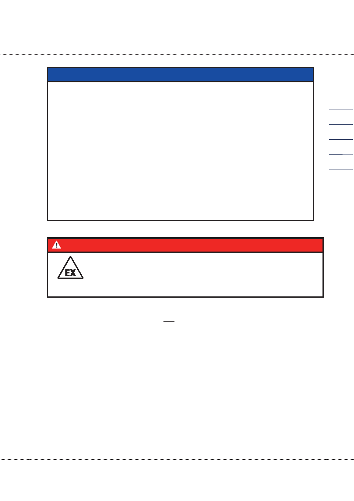
Danger
This symbol is used in the manual as a warning of the danger of
explosion; observe the instructions following the symbol. With
the danger of explosion, the following must be observed, in par-
ticular:
The flow computer ERZ2000-NG is not approved or designed for use in explosion-
prone areas. Installation must only take place in safe rooms. The ERZ2000-NG is
intended for installation in a control cabinet in an electronics room.
Install the device as specified in the operating manual. If the device is not installed as
specified in the operating manual, there may be a risk that other connected devices
have adequate explosion protection.
Inadequately qualified persons working on the equipment are unable to correctly es-
timate dangers. Explosions can be triggered. Only work on the equipment if you have
the appropriate qualifications.
Components can be damaged if you do not use suitable tools and materials. Only
use tools that are recommended for the respective work in the operating manual.
Mechanical installation
Mechanical installation must only be performed by appro-
priately qualified technicians.
1 About this manual
Manual ERZ 2000-NG · EN07 · 2019, May 13th
8
Electrical installation
Installation on electrical components must only be carried
out by qualified electricians.
Mechanical and/or elec-
trical insta
llation
These qualified personnel require training specifically for
work in explosion
-
prone areas. Qualified personnel are
persons who have training / education in accordance with
DIN VDE 0105, IEC 364 or comparable standards.
Caution
In general, the replacement of a flow computer ERZ2000-NG must only be car-
ried out by RMG Service.
1.2.4.3 Dangers during maintenance and repair
Operating personnel
The operating personnel use and operate the device in
the scope of the intended use.
Maintenance personnel
Work on the device must only be carried out by qualified
personnel who can carry out the respective tasks on the
basis of their technical training, experience and familiarity
with the applicable standards and requirements. These
qualified personnel are familiar with the applicable statu-
tory regulations for accident prevention and can inde-
pendently recognize and avoid potential dangers.
Maintenance and clean-
ing
Maintenance and cleaning must only be performed by
appropriately qualified technicians.
Danger
Inadequately qualified persons working on the equipment are unable to cor-
rectly estimate dangers. Explosions can be triggered.
Caution
The device can be damaged if it is not cleaned as specified in the operat-
ing manual. Only clean the device as specified in the operating manual.
- Only clean the device with a slightly damp cloth!

1 About this manual
Manual ERZ 2000-NG · EN07 · 2019, May 13th
9
Danger
The flow computer ERZ2000-NG must only be used as intended! (chapter 1.5
Areas of application
).
Avoid using the flow computer ERZ2000
-NG as a
potential climbing aid or as a
potential grip!
1.2.4.4 Qualification of personnel
Note
In general, the following is recommended for all persons working with or on the
flow computer ERZ2000
-NG:
x
Training / education for work in explosion-prone areas.
x
The capacity to be able to correctly estimate dangers and risks when work-
ing with the flow computer ERZ2000-NG and all connected devices.
x
Training / education by RMG for work with gas measuring devices.
x
Education / instruction in all national standards and directives to be com-
plied with for the work to be carried out on the flow computer ERZ2000-NG.
1.2.5 Risk assessment and minimization
According to assessment by qualified employees of RMG, the flow computer
ERZ2000-NG is subject to risks during its use. Risks can arise, for instance, during
use outside of the permissible temperature range. Impermissible current and voltage
values can trigger explosions in explosion-prone areas. Naturally, work must only be
carried out by trained personnel (see chapter 1.5 Areas of application), who are also
trained to recognize suitable tools and use them exclusively. These risks were sum-
marized alongside development and measures were taken to minimize these risks.
Measures for risk minimization:
- The maximum permissible temperature range is specified on the type plate of
the flow computer ERZ2000-NG. Operation of the device is only permitted
within these specified ranges.
1 About this manual
Manual ERZ 2000-NG · EN07 · 2019, May 13th
10
Danger
- The wiring from and installation of the flow computer ERZ2000-NG in ex-
plosion-
prone areas must only be carried out by trained personnel in ac-
cordance with EN60079-14 and in observance of national regulations.
- Qualified persons must satisfy the definitions in a
ccordance with DIN EN
0105 or IEC 364 or directly comparable standards.
-
Only trained and instructed personnel are permitted. Work on the meas-
uring system must only be carried out from qualified persons and in-
spected by responsible qualified supervisors.
- Qu
alified persons have been authorized by the person responsible for
safety of personnel to carrying out such work on the basis of their train-
ing, experience or instruction and familiarity with applicable standards,
provisions, accident prevention regulation
s and system conditions. It is
essential that these persons are able to recognize and avoid potential
dangers in good time.
1.2.6 Applicability of the manual
This manual describes the volume corrector ERZ2000-NG. The ERZ2000-NG is only
part of a complete system. The manuals of the other components of the system must
be observed. If you find contradictory instructions, contact RMG and/or the manufac-
turers of the other components.
Caution
Ensure that the power data of the current connection matches the specifica-
tions on the type plate. Observe any applicable national regulations in the
country of use. Use cable that is appropriate for the cable fittings.
1.2.6.1 Danger during operation
Observe the specifications of the system manufacturer and/or system operator.
Table of contents
Other RMG Measuring Instrument manuals


Popular Measuring Instrument manuals by other brands

Valeport
Valeport MIDAS WLR Hardware manual

Siemens
Siemens SITRANS FX330 operating instructions

Hanna Instruments
Hanna Instruments HI 718 quick start guide

Kamstrup
Kamstrup OMNIPOWER installation manual

Riken Keiki
Riken Keiki GX-8000 operating manual

Wavelength References
Wavelength References ClarityPlus Operator's manual


