2. Intended use
7
The testo 177 data loggers are used to save and read out separate readings and measurement
sequences. The readings are measured, saved and transmitted to a PC, to the testo 575 fast printer
or to the testo 580 data collector per infrared using testo ComSoft software.
Applications
testo 177-T1
Fast and affordable temperature monitoring
in refrigeration and deep freeze sector:
during transport, in refrigerated rooms,
in display cabinets, in containers
Fulfills guidelines in accordance with
EN 12830 standards *
testo 177-T2
Temperature monitoring with display:
during transport, in glass cabinets,
in refrigerated rooms, in containers,
in domestic housing
Fulfills guidelines in accordance with
EN 12830 standards *
testo 177-T3
Temperature logger with display and switch
(door contact) for monitoring transport:
transport monitoring, refrigerated room
monitoring, in containers, in warehouses
Fulfills guidelines in accordance with
EN 12830 standards *
testo 177-T4
Fast measurement of high temperatures:
during production processes, in laboratories
in heating installation sector, in containers
in domestic housing
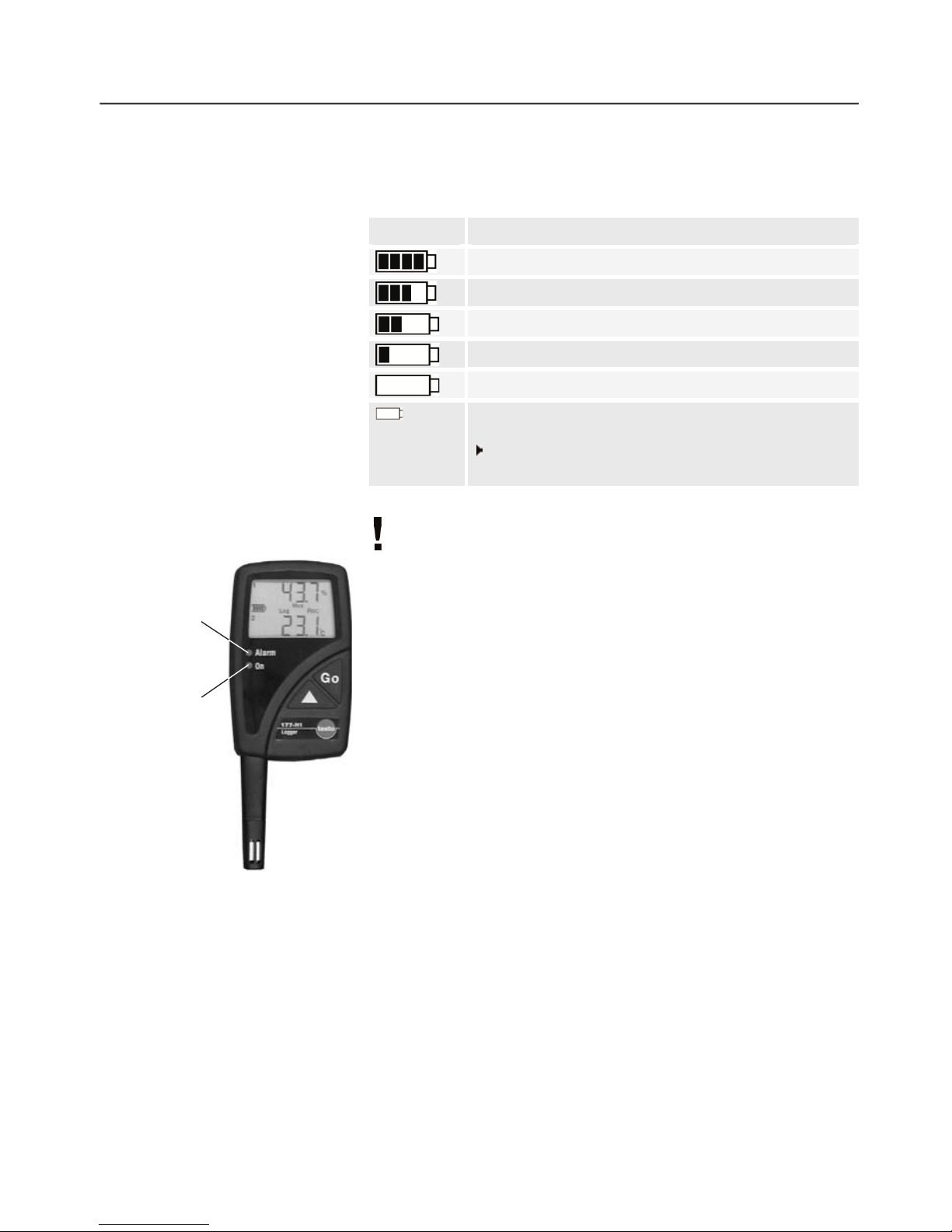
testo 177-H1
Monitoring of humidity and temperature
values with external temperature and dew
point measurement
in domestic housing, in the pharmaceutical
sector, in museums, in warehouses,
in industry
* In accordance with EN 12830, please ensure that a regular check and calibration in accordance with
EN 13486 (recommendation: once a year) is carried out on this instrument. Please contact us for
more detailed information.
Only for testo 177 - T3
The following components of the product are designed for continuous contact with
foodstuffs in accordance with the regulation
(EG) 1935/2004:
The measurement probe up to 1 cm before the probe handle or the plastic housing. If
provided, the information about penetration depths in the instruction manual or the mark(s)
on the measurement probes should be noted.