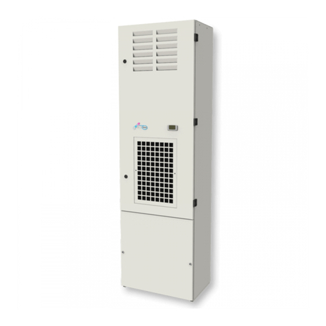
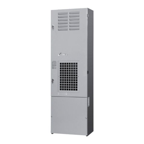
TEXA NOX06 User manual

C17000903R00PAQL22A
NOX
Installation, operation and maintenance manual
Cooling units for door or wall mounting
AT
T
E
N
T
I
O
N
!
Read carefully and completely before installation. Keep the manual until unit decommissioning.

2
ENGLISHENGLISH - «Translation of the original instructions» ENG
1. General Information........................................................................................................................................................8
1.1 Overview.......................................................................................................................................................8
1.2 Purpose of the Manual..................................................................................................................................8
1.3 Symbols Contained in this Manual................................................................................................................8
1.4 Retention of Documents................................................................................................................................8
1.5. Updates.......................................................................................................................................................8
1.6.TechnicalFeatures........................................................................................................................................8
1.7. Cooling UnitApplication................................................................................................................................8
1.7.1 Intended Use..............................................................................................................................8
1.7.2 Misuse........................................................................................................................................8
2. Technical Information.....................................................................................................................................................8
2.1 Operating Principles......................................................................................................................................8
2.2 Safety Devices............................................................................................................................................
.
8
3. Supply............................................................................................................................................................................8
4. Transport and handling..................................................................................................................................................8
5. Installation....................................................................................................................................................................
.
.9
5.1 Installation of External Installation Versions..................................................................................................9
5.2
Installation of Semi-Recessed Installation Versions
.........................................................................................9
6. Condensate runo pipe..................................................................................................................................................9
7. Electrical Connection.....................................................................................................................................................9
7.1 Two-Phase Models........................................................................................................................................9
7.2 Three-phase models.....................................................................................................................................9
7.3 Alarm Pins....................................................................................................................................................9
7.4 Sequencing (optional)...................................................................................................................................9
7.5 Modbus (optional).........................................................................................................................................9
8. First Start-Up and Regulation.........................................................................................................................................9
8.1 Electronic Thermostat...................................................................................................................................9
8.2 Electronic Board...........................................................................................................................................9
9. Maintenance................................................................................................................................................................10
10. Removal and Dismantling..........................................................................................................................................10
11. Troubleshooting.......... ...............................................................................................................................................10
12. Pictograms......................................................................................................................................................23-24-25
13. Technical data.......................................................................................................................................................26-27
14. Performances.......................................................................................................................................................28-29
15. Dimensions...........................................................................................................................................................30-31
16. Spare parts.................................................................................................................................................32-33-34-35
17. Guarantee.............................................................................................................................................................36-37
18. Assistance service.....................................................................................................................................................38
19.Notes..........................................................................................................................................................................39

8
ENG
1 General Information
WARNING
Read the following instructions carefully
before installing and using the product.
1.1 Overview
The product is manufactured by TEXA
INDUSTRIES S.r.l. in compliance with applicable
EC directives; more specically, it complies with
the requirements of the Machinery Directive
2006/42/EC and applicable harmonised and
safety regulations pursuant to the same directive.
1.2 Purpose of the Manual
This manual contains all information for safe
installation, use and maintenance of the product.
1.3 Symbols Contained in this Manual
WARNING
Indicates that failure to comply with these
instructions can lead to serious or even fatal
personal injury.
CAUTION
Indicates that failure to comply with these
instructions can lead to less serious injury or
damage to the product.
NOTICE
Indicates information which is important for use of
the machine.
1.4 Retention of Documents
This manual, in combination with the rest of the
digital/hardcopy documentation, represents an
integral part of the product.
Ensure this documentation is available for
consultation by all persons who use the product
and personnel authorised to carry out maintenance
operations.
NOTICE
Store the documentation with care in a clean, dry
location until the product has been disposed of.
5) applied to the cooling unit, and in table F.13 of
this manual
- Away from any sources of heat or hot air
- In an environment with adequate air exchange
- On switchboards with IP54 rating or higher.
If these requirements are not respected,
excessive condensation build-up may occur. As
a consequence, cable entry points or any other
openings in the enclosure should be well sealed.
- So that the compressor always remains upright.
1.7.2 Misuse
WARNING
Incorrect or careless use may cause irreparable
damage to the cooling unit and may lead to
hazardous situations.
NOTICE
The product warranty shall automatically be
rendered void if it is not used under the conditions
laid out above, and in the event of any tampering by
the customer. TEXA INDUSTRIES S.r.l. shall bear
no liability in the event of faults or malfunctions due
to failure to comply with the instructions provided.
NOTICE
To ensure correct operation, the specied
scheduled maintenance operations (see section
9) must be performed regularly.
2. Technical Information
2.1 Operating Principles
The cooling unit for electrical switchboard
enclosures works on the basis of a refrigeration
circuit consisting of four main components:
compressor, evaporator, condenser and
expansion device (gure F.12). The refrigeration
circuit is sealed and contains R134a refrigerant,
which is chlorine free and ozone friendly. The
unit is divided into two hermetically separated
sections where the ambient air and enclosure air
do not come into contact with one another and
are treated separately. The compressor (CP)
compresses the refrigerant, taking it to a high
pressure and high temperature. The compressor
then pushes the refrigerant through a heat-
exchanger coil, called the condenser (C), where it
is cooled by ambient air, thus passing from the gas
to the liquid state. In the liquid state it then passes
through the expansion valve (EXP), vaporising at
the outlet as it is now at a much lower pressure. It
is then received by the heat exchanger coil, called
the evaporator (E), by means of which it absorbs
heat from the enclosure air and passes from a
liquid state to gas. The enclosure is cooled down
in this manner. The gaseous refrigerant is then
drawn back into the compressor and this cycle is
repeated.
2.2 Safety Devices
WARNING
DO NOT disable the safety devices; any such
modication, in addition to causing a hazard,
would immediately invalidate the product
warranty.
WARNING
Ensure the following operations are performed
by qualied and authorised personnel,
equipped with appropriate PPE.
WARNING
Do not exceed the maximum manual handling
weight for loads specied by law. Use lifting
equipment as required.
CAUTION
Dispose of the packaging materials in an
environmentally friendly manner.
1.5. Updates
TEXA
INDUSTRIES
S.r.l.
reserves
the
right
to
update
its
products
and
the
corresponding
manuals based on technical progress without prior
notice.
Please
note
that
at
the
time
of
sale,
this
manual and the corresponding product may not be
considered inadequate only because they are not
subject to the above-mentioned progress.
1.6. Technical Features
The technical features and CE marking are given
on the data plate attached to the machine.
The
product
is
supplied
with
safety
instruction
manual,
wiring
diagram,
specic
test
report
and
CE declaration of conformity.
1.7. Cooling Unit Application
The
NOX
series
cooling
units
described
in
this manual
are
designed
and
built
to
cool
the
air
inside
electrical
switchboards
in
order
to
protect
components sensitive to thermal shock. They also
provide IP55 protection level against the inltration
of
contaminating
and
aggressive/corrosive
substances.
1.7.1 Intended Use
Use the
NOX
cooling unit:
- For cooling electrical switchboards
- Within the temperature limits and with the supply
voltages specied on the rating plate (F.04, pos.
Do not use the
NOX
cooling unit:
-
Under
any
condition
except
those
described
in
section
1.7.1
-
In
explosion-risk
atmospheres,
or
those
with
aggressive chemicals or excessive concentrations
of
dust,
solid
contaminants,
chemicals
or
oil
suspended in the air
-
Exposed
to
the
elements,
strong
radiated
heat
sources or strong magnetic elds
- With the doors of the electrical switchboard open,
or installed on enclosures without a minimum IP54
rating, due to excessive condensate formation
- With the temperature set below the dew point of
the ambient air
- With the condensate line closed or blocked o, or
in any case in which the condensate is not allowed
to run o freely
- Without the front panel
- With the cooling unit intake and outlet air ows
obstructed by walls or objects that are too close
To
this
end,
check
the
minimum
distances
as
regards
the
external
air
ow
(gure
F.02),
and
make sure there are no obstructions caused by the
switchboard
components
as
regards
the
internal
air ow.
-
In
a
position
other
than
that
for
which
it
was
designed, installed neither on moving, oscillating
nor vibrating parts
The refrigeration circuit is tted with an EN 12263
compliant
high-pressure
safety
switch
P
(gure
F.12)
set
to
the
maximum
working
pressure
of
the cooling unit. If this threshold is exceeded, the
pressure
switch
cuts
out
the
compressor,
before
restoring it automatically. The fans and compressor
have
an
(internal
or
external)
thermal
cut-out
switch that stops them in the case of overheating.
3. Supply
Inside the packaging you will nd:
1
Cooling unit
1
Safety instruction manual
1
CE conformity certicate
1
Test certicate
1
A4 drilling template
1
Wiring diagram
1
Installation kit containing (F.04):
- Flanged nuts (1)
- Flat washers (2)
- Grub screws (3)
2
Connectors, one for the power supply (F.04) and
one for the signals (F.05)
1
Self-adhesive sealing strip (F.04, 4)
1
Hose barb for the condensate discharge (F.10,
1)
Transport/handling
eyebolts
from
NOX12
to NOX60 (F.03)
4. Transport and handling
On
receipt,
check
that
the
packaging
does
not
show
signs
of
damage
from
transport.
Once
the
packaging
has
been
removed,
make
sure
the
product shows no signs of dents or damage and
that no oil is leaking from the circuit.
During transport and storage, the cooling unit must
be kept in a vertical position, as indicated on the
packaging (gure
F.01) and must not be exposed
to temperatures above 70°C or below -20°C. To lift
the cooling unit in a safe manner use the supplied
eyebolts (included from NOX12); these should
be tted into the threaded inserts located on the
top of the cooling unit (gure
F.03).

9
ENG
NOTICE
Immediately contact TEXA INDUSTRIES S.r.l.
in writing in the event of any damage or other
discrepancies.
5. Installation
WARNING
Disconnect power before starting any work
inside the switchboard.
WARNING
Installation of the machine must be performed
only by authorised and qualied personnel
using appropriate PPE.
CAUTION
Debur holes and slots to prevent cuts, above
all during the installation phase.
(gure F.13). These models nevertheless have
an emergency condensate outlet which can be
carried outside as described above. If the cooling
unit is used with the doors of the enclosure open,
excessive quantities of condensate will form and
this is an unauthorised condition of use (gure
F.09). We suggest using a position switch on the
door connected to the cooling unit’s digital input
to stop the unit if the door is opened. (See section
7.3)
7. Electrical Connection
WARNING
The electrical connection and any work on the
system or on electrical components must be
performed solely by specialised and authorised
personnel in compliance with electrical code
and any other applicable regulations.
WARNING
Isolate the power to the enclosure during the
connection phase.
WARNING
Ensure the machine is correctly earthed.
CAUTION
Make sure the supply voltage is compatible
with the voltage on the cooling unit’s rating
plate.
CAUTION
The power supply must be protected upline
of the machine using appropriate time-delay
fuses (type T) or circuit breakers with K-curve,
per the indications given in table F.13.
Connect the supply cable in accordance with
gure F.14.
7.1 Two-Phase Models
The two-phase models can operate with two
dierent supply voltages: 460V 2~50-60Hz and
400V 2~50-60Hz. If the available power supply
is 460V 2~50-60Hz, connect terminals L1(0) and
L3(460) on the terminal board (gure F.14). If,
on the other hand, the available supply voltage
is 400V 2~50-60Hz, connect terminals L1(0) and
L2(400) on the same terminal board.
The UL-listed models are tted with fuses on
the 460V 2~50-60Hz supply line located in the
corresponding fuse holders in the rear part of the
cooling unit (gure F.16).
7.2 Three-phase models
The three-phase UL-listed models with 460V 3~
60 Hz power supply can also be powered with
400V 3~ 50 Hz voltage by opening the rear panel
and modifying the connection of the cables on
the quick-release connector (gure F.19). On the
contrary, the models with only CE marking are
factory set for 400V 3~ 50 Hz and can be powered
with 460V 3~ 60 Hz voltage by modifying the
connection with the same procedure described
previously.
The UL-listed models are tted with fuses on
the 460V 3~ 60Hz supply line located in the
corresponding fuse holders in the rear part of the
cooling unit (gure F.16).
7.3 Alarm Pins
(gure F.15)
The input/output signals from the electronic control
unit are managed via the alarm pins:
- Alarm signals from the electronic control unit can
be taken from positions 1-2-3; in the event of an
alarm, the digital output relay will change state
- A digital input for voltage free contacts is available
on terminals 4-5
The cooling unit’s electronic control unit is
programmed to generate an alarm when the
digital input is open. When the digital input is not
being used, it is therefore necessary to bridge it
by connecting terminals 4 and 5 together with a
cable.
7.4 Sequencing (optional)
(gure F.17)
It is possible to connect two cooling units together
in sequence via the red 4-pole connector on the
rear of the machine; the cable is not supplied as
standard.
See the control unit manual to set the necessary
parameters.
7.5 Modbus (optional)
(gure F.18)
It is possible to make a modbus connection via the
4-pole connector on the rear of the machine; the
cable is not supplied as standard.
See the control unit manual to set the necessary
parameters.
8. First Start-Up and Regulation
CAUTION
If, prior to installation, the cooling unit was left
in an incorrect position (gure F.01), wait at
least 8 hours before switching it on.
Otherwise, 30 minutes is more than enough
time for the oil to return to the compressor,
after which the cooling unit can be powered
up.
Once voltage is applied, the enclosure air
intake fan will operate intermittently, making the
temperature inside the enclosure even. If this
temperature exceeds 2K above the set point, both
the compressor and external air fan will turn on,
causing the cooling cycle to start. This then stops
when the inside temperature reaches the set point.
The thermostat is factory-set to 35°C. The setpoint
can be set between 20°C and 45°C.
NOTICE
To save energy and minimise the production
of condensate, we recommend not setting the
setpoint below 30 °C.
Install the cooling unit with the enclosure air intake
hole in the highest possible point.
Ensure the xing elements and couplings will not
foul the equipment inside the enclosure itself.
If the cooling unit is to be installed on the door of
an electrical switchboard, make sure the door can
take the weight.
The
unit
must
be
installed
in
a
vertical
position.
Maximum permitted deviation from the vertical is
2°.
5.1 Installation of External Installation Versions
The cooling unit must be installed on the outside
of
the
electrical
switchboard.
Drill
the
holes
and
make the necessary cuts in the enclosure (gure
F.04) using the drilling template supplied with the
unit. Fit the sealing strip on the cooling unit on the
side
connected
to
the
enclosure
and
follow
the
assembly diagram (gure
F.04).
5.2
Installation
of
Semi-Recessed
Installation
Versions
Thanks
to
its
modular
conguration,
depending
on requirements the cooling unit can be installed
on the exterior of the electrical switchboard (gure
F.05)
or
semi-recessed
(gure
F.06)
without
the
need
for
further
accessories.
Depending
on
the
installation
option,
drill
the
holes
and
make
the
necessary cuts in the switchboard using the drilling
template supplied with the unit. Fit the sealing strip
on the cooling unit on the side connected to the
enclosure.
Follow
the
installation
diagram
given,
depending on the required installation type.
6. Condensate runo pipe
The condensate which, depending on the ambient
temperature and humidity conditions, forms on the
cooling unit which cools the enclosure air, is not
a
malfunction
but
a
normal
phenomenon
of
the
cooling unit. In models
NOX04-NOX06-NOX08,
this
condensate is taken outside through a hose at the
bottom of the cooling unit. It is possible to screw
on the hose barb supplied with the machine (gure
F.10) on which an 8 mm ID hose can be tted to
carry the condensate to another position, so that
the
discharge
can
be
made
at
a
point
where
it
does not represent a slipping hazard to personnel.
In
this
case,
make
sure
the
condensate
ows
without
any
hindrance.
Avoid
horizontal
lengths
of more than 0.5 metres, uphill sections and the
accidental formation of traps (gure
F.07). The end
of the condensate runo pipe must always be free
and never underwater. The end of the condensate
runo pipe must therefore not be placed inside a
condensate collection container (gure
F.08).
Models
NOX10
to
NOX60
are
tted
with
a condensate
evaporation
device
which
operates via
the
hot
(outlet)
tube
of
the
compressor
8.1 Electronic Thermostat
The NOX04 model is tted with a TX050
electronic thermostat.
See
the
specic
manual
C17000199 for
the
functions
of
this
thermostat
and
how
to program it.
8.2 Electronic Board
All other models in the NOX range are
equipped with an electronic board TX-i40 and a
display on which the operator can modify the
machine parameters. See the specic manual
TX-I40 MANUAL for the functions of this
thermostat and how to program it.
TEXA INDUSTRIES S.r.l. nor B&R Enclousres
(it's distributor in Australia)
shall be in no way
held
liable for any alterations the customer may
make
to the default parameters if they have not
received
authorisation to do so.
NOTICE

10
ENG
9. Maintenance
WARNING
Before commencing any operation, shut o the
power supply to the machine.
WARNING
Scheduled and extraordinary machine
maintenance must be performed only by
authorised and qualied personnel using
appropriate PPE.
WARNING
Wait for the surfaces of the internal components
to come to ambient temperature.
CAUTION
DO NOT use acidic or ammable detergents to
clean the product.
The cooling unit is the low maintenance type, so
no lter change is required. The only maintenance
required is for the internal components, which
should be checked regularly, as indicated in the
following table, and cleaned with compressed air
at a maximum pressure of 4 bar (gure F.11).
NOTICE
Increase the frequency of these operations if
the machine is operated in very dusty and dirty
environments.
10 Removal and Dismantling
WARNING
Before commencing any operation, shut o the
power supply to the machine.
WARNING
Removal and dismantling of the machine must
be performed only by authorised and qualied
personnel using appropriate PPE.
The cooling unit contains R134a refrigerant and
small quantities of lubricating oil. These are
polluting substances and must not be dumped.
Have personnel certied per Regulation (EU)
517/2014 recover the refrigerant so that it can be
reused, regenerated or destroyed.
Job
Check the external air
heat exchanger and clean
if necessary.
Check eectiveness of the
condensate discharge.
Check the fans for any
overheating or excessive
vibrations.
Frequency
Every 3
months
Every 3
months
Every 6
months
Remedy
This is not a malfunction of the cooling unit.
To verify functioning when testing, lower the thermostat setting until
the compressor and external fan start working and then reset the
thermostat.
Change the adjustment (or antifreeze) thermostat
This is not a malfunction of the cooling unit.
Make sure the power cable has been connected well to the
terminals.
Check that the cubicle doors and switches are closed
Call a refrigeration expert or the Manufacturer’s Technical Assis-
tance Service
Call a refrigeration expert or the Manufacturer’s Technical Assis-
tance Service
Change the internal fan’s capacitor
Change the internal fan
Change the amperometric protector
Change the relay or PTC for compressor starting
Change the capacitor for compressor starting
Call a refrigeration expert or the Manufacturer’s Technical Assis-
tance Service
Call a refrigeration expert or the Manufacturer’s Technical Assis-
tance Service
Change the contactor
Change the cooling unit with another of greater capacity
Clean the evaporator coil
See if there are any obstacles inside the enclosure to hinder the
ow of recycling air
Call a refrigeration expert or the Manufacturer’s Technical Assis-
tance Service
Check thermostat setpoint
Ventilate the premises where the enclosure is installed to keep
ambient temperature lower.
Clean the exchanger with compressed air and detergent
Ventilate the premises where the enclosure is installed to keep
ambient temperature lower.
Clean the coil with compressed air and detergent
This is not a malfunction of the cooling unit. Close the enclosure
door or disable the cooling unit
This is not a malfunction of the cooling unit. Seal enclosure open-
ings, e.g. for passage and upward path of wires
Check seal and remedy
Causes
The temperature inside the enclosure is lower than what
is set on the adjustment thermostat.
The adjustment (or antifreeze) thermostat has failed
No electricity getting to the unit.
Cooling unit empty of uid
Compressor mechanical failure
Internal fan capacitor failed
Internal fan failed
Compressor’s amperometric protector failed (external to
the compressor, where present)
Relay or PTC for compressor starting failed
Capacitor for compressor starting failed (where present)
Compressor motor electrical failure
High pressure safety switch failed
Compressor contactor failed (where present)
Cooling unit under sized for the heat dissipated inside
the enclosure
Antifreeze thermostat triggered (where present)
Insucient gas in the cooling unit
Thermostat set point incorrect
High pressure safety switch triggered:
Ambient temperature over the maximum working
limit
Heat exchanger coil (condenser) either dirty or
clogged
Thermal protector inside the compressor triggered:
Ambient temperature over the maximum working
limit
Heat exchanger coil (condenser) either dirty or
clogged
Too much ambient air inside the enclosure
Enclosure protection level is below IP54
The enclosure/cooling unit connecting seal has been t-
ted incorrectly
Conditions
The internal fan works, the external fan and com-
pressor do not work.
No component works
Compressor, external and internal fan work
Compressor and external fan work, internal fan
does not work
External and internal fan work, compressor does
not work
External and internal fans work, compressor works
all the time
Inside fan works, external fan and compressor
work irregularly
External and internal fans work, compressor works
irregularly
Enclosure door open
Enclosure door closed
Malfunction
It fails to cool
It is not cooling enough
Too much condensate forming
•
•
•
•
•
•
•
•
12. Troubleshooting
•
•
•
•

23
F.03F.01
F.04
F.02
F.05 F.06
12. Pictograms

24
F.10
F.13
F.07 F.08
F.09
F.11 F.12
12. Pictograms

25
F.14
230V ~ 50-60Hz
115V ~ 50-60Hz
400V 3~ 50Hz
460V 3~ 60Hz
400V 2~ 50-60Hz 460V 2~ 50-60Hz
F.15
LN
L1L2 PE
L1 L2 PE
RSPE
T
PE
COMNO NC
ALARM
DIGITAL
INPUT
F.17F.16
F.19F.18
400V 3~ 50Hz 460V 3~ 60Hz
12. Pictograms

28
NOX06
NOX08 NOX10
NOX12 NOX16
14. Performances
F.21

29
P(W)
Useful cooling output
Nutzkühlleistung
Puissance frigorique utilisée
Potencia frigorica útil
ESP
ENG
ITA
DEU
FRA
Ta (°C)
Ambient temperature
Umgebungstemperatur
Température ambiante
Temperatura ambiente
Ti (°C)
Enclosure internal temperature
Temperatura interna armadio
Schaltschrank-Innentemperatur
Température intérieure armoire
Temperatura interior armario
NOX20 NOX30
NOX40 NOX60
14. Performances
F.21
Poenza frigorifera utile Tempeatura ambiente

30
NOX06-08NOX10
15.
Dimensions
F.22
External Mounting Semi-recessed mounting

31
NOX12-16-20NOX30-40NOX60
15. Dimensions
F.22
External Mounting Semi-recessed mounting
External Mounting
External Mounting

32
En caso de pedido depiezas de
repuesto, siempre indicar los
1Front structure Scocca anteriore Vorderer
Gehäuserahmen Coque avant Bastidor delantero
2Condenser Condensatore Verüssiger Condenseur Condensador
3Evaporator Evaporatore Verdampfer évaporateur Evaporador
4Compressor Compressore Kompressor Compresseur Compresor
5Condenser fan Ventilatore
condensatore Verüssigerlüfter Ventilateur du condenseur Ventilador
condensador
6Evaporator fan Ventilatore evaporatore Verdampferlüfter Ventilateur évaporateur Ventilador
evaporador
7Electric Control Regolatore elettrico Elektrische Regler Régulateur électrique Regulador eléctrico
8Display Visualizzatore Anzeige Acheur Visualizador
9Electronic Board Scheda elettronica Elektronikkarte Carte électronique Tarjeta electrónica
10 Autotransformer Autotrasformatore Spartransformator Autotransformateur Autotransformador
11 Assembly accessory
kit Sacchetto accessori di
montaggio Beutel mit Montagezu-
behör Enveloppe des accessoi-
res de montage Bolsa de accesorios
de montaje
ENG ITA DEU FRA ESP
16. Spare parts

33
NOX06-08
16. Spare parts
F.23

34
NXT10
NXT12-16-20
16. Spare parts
F.23

35
NOX30-40
NOX60
16. Spare parts
F.23
This manual suits for next models
8
Table of contents
Other TEXA Air Conditioner manuals
Popular Air Conditioner manuals by other brands

ARDES
ARDES AR5R003 Instructions for use

Samsung
Samsung AC024JXADCH installation manual

Mitsubishi Electric
Mitsubishi Electric Mr.Slim MS-GK36VA operating instructions

Frigidaire
Frigidaire 220218A007 use and care manual

Hitachi
Hitachi RAD-25NH4 Service manual

Frigidaire
Frigidaire FAA074S7A12 Use & care manual