1
SPRUIK1–June 2018
Submit Documentation Feedback Copyright © 2018, Texas Instruments Incorporated
AWR1642 Obstacle Detection Sensor (AWR1642BOOST-ODS) Single-Chip
mmWave Sensing Solution
User's Guide
SPRUIK1–June 2018
AWR1642 Obstacle Detection Sensor
(AWR1642BOOST-ODS)
Single-Chip mmWave Sensing Solution
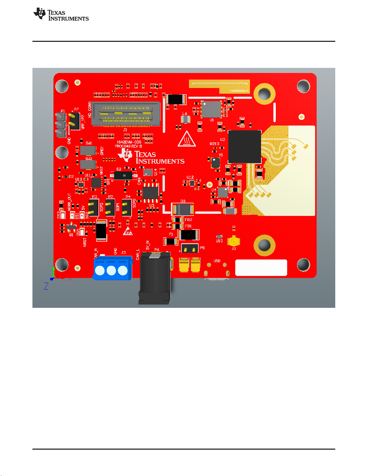
The AWR1642 Obstacle Detection Sensor from Texas Instruments is an easy-to-use evaluation board for
the AWR1642 mmWave sensing device, with direct connectivity to the microcontroller (MCU)
LaunchPad™ Development Kit. The Obstacle Detection Sensor contains everything required to start
developing software for on-chip C67x DSP core and low-power ARM®R4F controllers, including onboard
emulation for programming and debugging as well as onboard buttons and LEDs for quick integration of a
simple user interface.
Contents
1 Getting Started............................................................................................................... 2
1.1 Introduction .......................................................................................................... 2
1.2 Key Features ....................................................................................................... 2
1.3 Kit Contents.......................................................................................................... 2
2 Hardware...................................................................................................................... 3
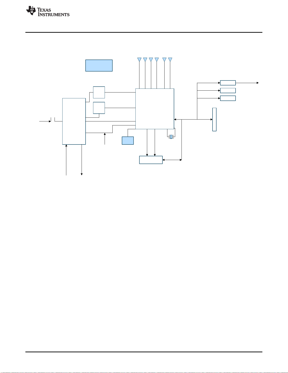
2.1 Block Diagram....................................................................................................... 5
2.2 Power Connections................................................................................................. 6
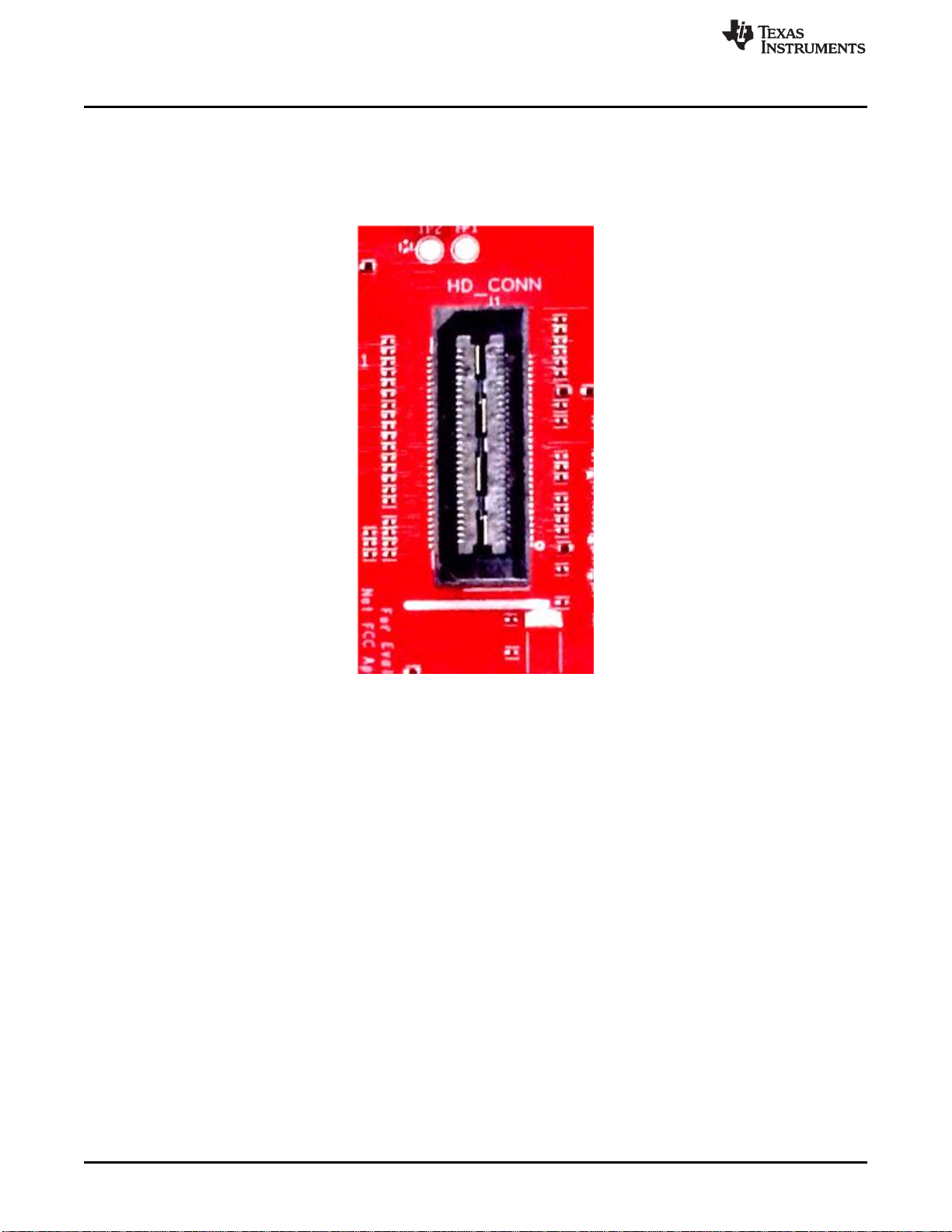
2.3 Connectors .......................................................................................................... 6
2.4 PC Connection..................................................................................................... 10
2.5 Connecting the Obstacle Detection Sensor to the LaunchPad or the MMWAVE-DEVPACK........... 11
2.6 Antenna............................................................................................................. 11
2.7 Jumpers, Switches, and LEDs................................................................................... 13
3 Design Files and Software Tools......................................................................................... 17
3.1 Hardware........................................................................................................... 17
3.2 Software, Development Tools, and Example Code........................................................... 17
4 Design Revision History .................................................................................................. 17
5 Mechanical Mounting of PCB............................................................................................. 18
6 PCB Storage and Handling Recommendations........................................................................ 18
7 Troubleshooting ............................................................................................................ 18
Trademarks
LaunchPad, Code Composer Studio are trademarks of Texas Instruments.
ARM is a registered trademark of ARM Limited.
Windows is a registered trademark of Microsoft Corporation.
All other trademarks are the property of their respective owners.