1
SLUUBW8–July 2018
Submit Documentation Feedback Copyright © 2018, Texas Instruments Incorporated
TPS543C20EVM-054 40-A Single Phase Synchronous Step-Down Converter
User's Guide
SLUUBW8–July 2018
TPS543C20EVM-054 40-A Single Phase Synchronous
Step-Down Converter
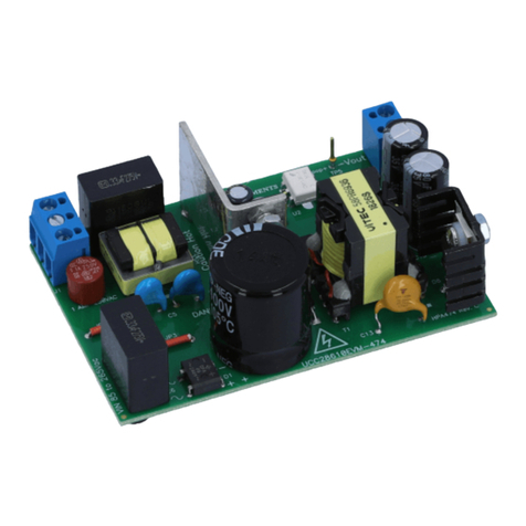
This user's guide describes the characteristics, operation, and use of the TPS543C20EVM-054 evaluation
module (EVM). The user's guide includes test information, descriptions, and results. A complete schematic
diagram, printed-circuit board layouts, and bill of materials are also included in this document. Throughout
this user's guide, the abbreviations EVM, TPS543C20EVM-054, and the term evaluation module are
synonymous with the TPS543C20EVM-054, unless otherwise noted.
Contents
1 Introduction ................................................................................................................... 3
1.1 Before You Begin................................................................................................... 3
2 Description.................................................................................................................... 4
2.1 Typical End-User Applications .................................................................................... 4
2.2 EVM Features....................................................................................................... 4
3 EVM Electrical Performance Specifications.............................................................................. 4
4 Schematic..................................................................................................................... 5
5 Test Equipment .............................................................................................................. 6
6 BSR054EVM ................................................................................................................. 7
7 List of Test Points, Jumpers, and Switch................................................................................. 8
8 Test Procedure............................................................................................................... 9
8.1 Line and Load Regulation Measurement Procedure........................................................... 9
8.2 Efficiency............................................................................................................. 9
8.3 Equipment Shutdown............................................................................................. 10
9 Performance Data and Typical Characteristic Curves................................................................. 10
9.1 Efficiency ........................................................................................................... 10
9.2 Power Loss......................................................................................................... 10
9.3 Load Regulation................................................................................................... 11
9.4 Transient Response............................................................................................... 11
9.5 Output Ripple ...................................................................................................... 12
9.6 Control On.......................................................................................................... 13
9.7 Control On and Off................................................................................................ 14
9.8 Thermal Image..................................................................................................... 15
10 EVM Assembly Drawing and PCB Layout .............................................................................. 16
11 List of Materials............................................................................................................. 26
List of Figures
1 BSR054EVM Schematic.................................................................................................... 5
2 BSR054EVM Overview ..................................................................................................... 7
3 Tip and Barrel Measurement............................................................................................... 7
4 Efficiency of 0.9-V Output vs Load....................................................................................... 10
5 Power Loss of 0.9-V Output vs Load.................................................................................... 10
6 Load Regulation of 0.9-V Output......................................................................................... 11
7 Transient Response of 0.9-V Output at 12-VIN, Transient is 15 A to 25 A to 15 A, the Step is 10 A at 40
A/µs .......................................................................................................................... 11
8 Output Ripple and SW Node of 0.9-V Output at 12-VIN, 40-A Output............................................... 12
9 Output Ripple and SW Node of 0.9-V Output at 12-VIN, 0-A Output ................................................ 12
