www.ti.com
2SBAU200C–June 2012–Revised April 2020
Submit Documentation Feedback
Copyright © 2012–2020, Texas Instruments Incorporated
Performance Demonstration Kit for the ADS131E08
4 Using the Software......................................................................................................... 14
5 ADS131E08 Analysis Tools............................................................................................... 22
6 Bill of Materials (BOM), Layout, and Schematic ....................................................................... 28
List of Figures
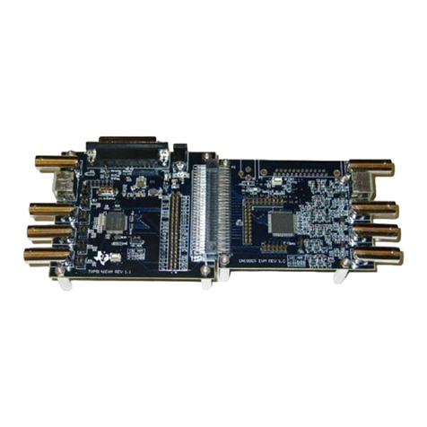
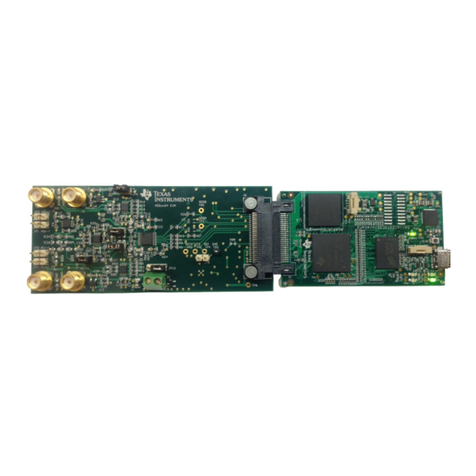
1 ADS131E08EVM-PDK ...................................................................................................... 1
2 ADS131E08EVM-PDK Kit.................................................................................................. 4
3 Initialization of ADS131E08EVM GUI..................................................................................... 6
4 License 1...................................................................................................................... 6
5 License 2...................................................................................................................... 6
6 New Hardware Wizard Screen 1 .......................................................................................... 7
7 New Hardware Wizard Screen 2 .......................................................................................... 7
8 New Hardware Wizard Screen 3 .......................................................................................... 8
9 Completion of the First USB Driver........................................................................................ 8
10 Second New Hardware Wizard Screen................................................................................... 9
11 Installing the USBStyx Driver .............................................................................................. 9
12 File Save Option Under Save Tab....................................................................................... 14
13 Channel Registers GUI for the Configuration Registers .............................................................. 15
14 Channel Control Register GUI Panel: Single Channel Enabled ..................................................... 16
15 Channel Control Registers GUI Panel: All Channels Enabled....................................................... 16
16 Example of Internal Test Signals Viewed on the Scope Display Tab............................................... 17
17 Internal Temperature Sensor ............................................................................................. 18
18 Eight-Channel Read of Internal Temperature Data.................................................................... 18
19 GPIO Control Register GUI Panel ....................................................................................... 19
20 Fault Status Indicator...................................................................................................... 20
21 Device Register Settings.................................................................................................. 21
22 Scope Tool Features....................................................................................................... 22
23 Scope Analysis Tab (Noise Levels for Each Channel Shown)....................................................... 23
24 Zoom Option on the Waveform Examination Tool..................................................................... 23
25 Histogram Bins ............................................................................................................. 24
26 Statistics for the Signal Amplitude of Eight Channels................................................................. 24
27 Analysis→FFT Graph of Normal Electrode Configuration............................................................ 25
28 Analysis→FFT→AC Analysis Parameters: Windowing Options..................................................... 26
29 Analysis→FFT→FFT Analysis: Input Short Condition ................................................................ 26
30 Changing the User-Defined Dynamic Range for Channel 1.......................................................... 27
31 FFT Plot Using Waveform Zoom Function.............................................................................. 27
List of Tables
1 Related Documentation..................................................................................................... 1
2 Power-Supply Test Points................................................................................................. 10
3 Analog Supply Configurations............................................................................................ 11
4 Digital Supply Configurations (DVDD and DGND)..................................................................... 11
5 CLK Jumper Options....................................................................................................... 12
6 External Reference Jumper Options..................................................................................... 12
7 Auxiliary Connector Test Signals and Test Points..................................................................... 12
8 Serial Interface Pinout..................................................................................................... 13
9 Register Assignments: Channel-Specific Settings..................................................................... 16
10 GPIO: General-Purpose I/O Register.................................................................................... 19
11 ADS131E08 Bill of Materials ............................................................................................. 28
