Table of Contents
1 Definitions............................................................................................................................................................................... 3
2 Introduction.............................................................................................................................................................................3
2.1 Key Features......................................................................................................................................................................4
2.2 Quick Setup........................................................................................................................................................................6
3 Board Setup Details................................................................................................................................................................8
3.1 Block Diagram....................................................................................................................................................................8
3.2 EVM High-Level Summary.................................................................................................................................................9
4 Configuration Options..........................................................................................................................................................10
4.1 Bootstrap Options............................................................................................................................................................ 10
4.2 SGMII/Fiber Interface.......................................................................................................................................................13
4.3 RGMII...............................................................................................................................................................................13
4.4 Clock Output.................................................................................................................................................................... 13
4.5 Clock Input....................................................................................................................................................................... 13
4.6 Switch Configuration Options...........................................................................................................................................14
5 Schematics............................................................................................................................................................................16
6 Revision History................................................................................................................................................................... 22
List of Figures
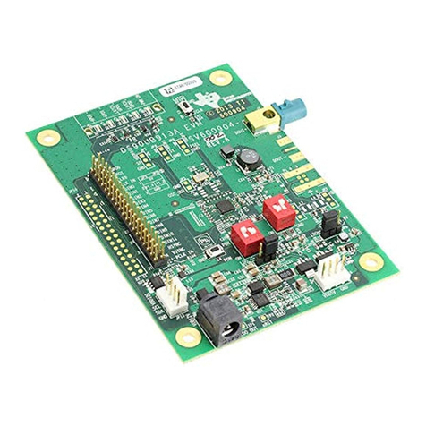
Figure 2-1. DP83869EVM – Top Side..........................................................................................................................................4
Figure 2-2. DP83869EVM – Bottom Side.................................................................................................................................... 5
Figure 2-3. Onboard Power Supply Connection.......................................................................................................................... 6
Figure 2-4. Jumper Placements for Onboard Power................................................................................................................... 6
Figure 3-1. DP83869EVM Block Diagram................................................................................................................................... 8
Figure 4-1. EVM Strap Jumpers................................................................................................................................................ 10
Figure 4-2. Onboard Clock........................................................................................................................................................ 13
Figure 4-3. External Clock Input................................................................................................................................................ 13
Figure 5-1. Schematic Page 1................................................................................................................................................... 16
Figure 5-2. Schematic Page 2................................................................................................................................................... 17
Figure 5-3. Schematic Page 3................................................................................................................................................... 18
Figure 5-4. Schematic Page 4................................................................................................................................................... 19
Figure 5-5. Schematic Page 5................................................................................................................................................... 20
Figure 5-6. Schematic Page 6................................................................................................................................................... 21
List of Tables
Table 1-1. Terminology.................................................................................................................................................................3
Table 3-1. EVM Applications........................................................................................................................................................9
Table 4-1. 4 Level Straps........................................................................................................................................................... 10
Table 4-2. 2 Level Straps........................................................................................................................................................... 10
Table 4-3. PHY Strap Table........................................................................................................................................................11
Table 4-4. Functional Mode Strap Table.....................................................................................................................................11
Table 4-5. Copper Ethernet Strap Table.....................................................................................................................................11
Table 4-6. 1000Base-X Strap Table........................................................................................................................................... 12
Table 4-7. 100Base-X Strap Table............................................................................................................................................. 12
Table 4-8. Bridge Mode Strap Table.......................................................................................................................................... 12
Table 4-9. 100 M Media Converter Strap Table......................................................................................................................... 12
Table 4-10. 1000 M Media Strap Table...................................................................................................................................... 12
Table 4-11. 4-Pin Dip Switch Modes.......................................................................................................................................... 14
Trademarks
All trademarks are the property of their respective owners.
Table of Contents www.ti.com
2DP83869 Evaluation Module SNLU237A – SEPTEMBER 2018 – REVISED JANUARY 2024
Submit Document Feedback
Copyright © 2024 Texas Instruments Incorporated
