2SNLU177–July 2016
Submit Documentation Feedback
Copyright © 2016, Texas Instruments Incorporated
Contents
Contents
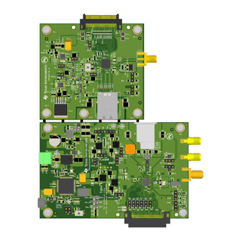
1 DS90UB96X-Q1EVM User's Guide.......................................................................................... 5
1.1 General Description ......................................................................................................... 5
1.2 Features....................................................................................................................... 6
1.3 System Requirements....................................................................................................... 7
1.4 Contents of the Demo Evaluation Kit ..................................................................................... 7
1.5 Applications Diagram........................................................................................................ 7
1.6 Typical Configuration........................................................................................................ 8
1.7 Quick Start Guide............................................................................................................ 9
1.8 Demo Board Connections .................................................................................................. 9
1.8.1 Power Supply........................................................................................................ 9
1.8.2 Power Over Coax Interface...................................................................................... 10
1.8.3 MIPI CSI-2 Output Signals....................................................................................... 11
1.8.4 FPD-Link III Signals............................................................................................... 13
1.8.5 I2C Interface........................................................................................................ 13
1.8.6 Control Interface................................................................................................... 14
1.9 Enable and Reset .......................................................................................................... 15
1.10 ALP Software Setup ....................................................................................................... 16
1.10.1 System Requirements........................................................................................... 16
1.10.2 Download Contents.............................................................................................. 16
1.10.3 Installation of the ALP Software................................................................................ 16
1.10.4 Startup - Software Description.................................................................................. 17
1.10.5 Information Tab................................................................................................... 18
1.10.6 Registers Tab..................................................................................................... 19
1.10.7 Registers Tab - Address 0x00 Selected ...................................................................... 20
1.10.8 Registers Tab - Address 0x00 Expanded..................................................................... 21
1.10.9 Scripting Tab...................................................................................................... 22
1.10.10 Sample ALP Python Script .................................................................................... 22
1.10.10.1 Initialization ................................................................................................. 22
1.11 Troubleshooting ALP Software........................................................................................... 27
1.11.1 ALP Loads the Incorrect Profile ................................................................................ 27
1.11.2 ALP does not detect the EVM.................................................................................. 30
1.12 Typical Connection and Test Equipment................................................................................ 32
1.13 Termination Device ........................................................................................................ 32
1.14 Typical Test Setup ......................................................................................................... 32
1.15 Equipment References .................................................................................................... 34
1.16 Cable References .......................................................................................................... 34
1.17 Bill of Materials ............................................................................................................. 35
2 PCB Schematics................................................................................................................. 46
3 Board Layout..................................................................................................................... 53
