Table of Contents
1 Overview..................................................................................................................................................................................4
1.1 INA233EVM Kit Contents...................................................................................................................................................4
1.2 Related Documentation from Texas Instruments............................................................................................................... 5
2 INA233EVM Hardware............................................................................................................................................................ 5
2.1 Theory of Operation for INA233 Hardware........................................................................................................................ 6
2.2 Signal Definitions of H1 (10-Pin Connector Socket).......................................................................................................... 7
2.2.1 SM-USB-DIG Platform Description..............................................................................................................................8
3 INA233EVM Hardware Setup................................................................................................................................................. 9
3.1 Electrostatic Discharge Warning........................................................................................................................................ 9
3.2 One-Time INA233EVM GUI Software Setup......................................................................................................................9
3.2.1 Hardware Requirements..............................................................................................................................................9
3.2.2 Software Installation.................................................................................................................................................... 9
3.3 Configuration of INA233EVM Jumper Settings................................................................................................................ 10
3.4 Connecting the Hardware.................................................................................................................................................11
3.4.1 System Power Up......................................................................................................................................................12
3.5 INA233EVM Features...................................................................................................................................................... 13
3.5.1 J3: I2C VS Control Setting......................................................................................................................................... 13
3.5.2 J1: I2C Address Hardware Setting (A0).....................................................................................................................13
3.5.3 J2: I2C Address Hardware Setting (A1).....................................................................................................................13
3.5.4 External I2C Lines and Test Points SCL and SDA.....................................................................................................13
3.5.5 IN+/IN– Input Filter (R1, R2, and C1)........................................................................................................................ 13
3.5.6 Shunt Monitor Configuration......................................................................................................................................14
4 INA233EVM Software Overview...........................................................................................................................................15
4.1 Starting the INA233EVM Software...................................................................................................................................15
4.2 Configuring the INA233EVM Software.............................................................................................................................16
4.2.1 I2C Address Selection................................................................................................................................................17
4.2.2 Set the Configuration Register (MFR_ADC_CONFIG)..............................................................................................18
4.2.3 Set Calibration Register (MFR_CALIBRATION)........................................................................................................19
4.2.4 Set the MFR_DEVICE_CONFIG Register.................................................................................................................20
4.2.5 Set the MFR_ALERT_MASK.....................................................................................................................................20
4.2.6 Set the Warning Limit Registers................................................................................................................................ 20
4.3 Using the INA233EVM Software...................................................................................................................................... 21
4.3.1 Read Data Tab...........................................................................................................................................................21
4.3.2 Status Register Tab................................................................................................................................................... 22
4.3.3 Register Map Tab...................................................................................................................................................... 23
4.3.4 Plots Tab....................................................................................................................................................................24
5 INA233EVM Documentation.................................................................................................................................................25
5.1 Schematic........................................................................................................................................................................ 25
5.2 PCB Layout...................................................................................................................................................................... 26
5.3 Bill of Materials.................................................................................................................................................................28
6 Revision History................................................................................................................................................................... 29
List of Figures
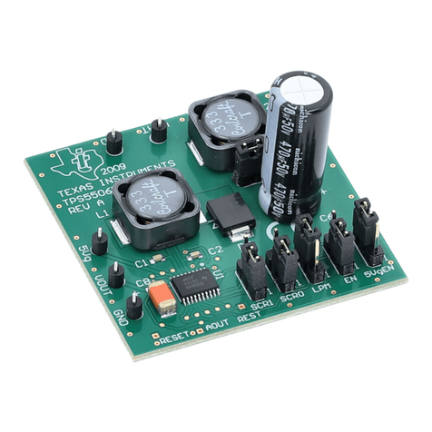
Figure 1-1. INA233EVM Evaluation Module................................................................................................................................ 1
Figure 1-1. Hardware Included With INA233EVM Kit.................................................................................................................. 4
Figure 2-1. INA233EVM Hardware Setup....................................................................................................................................5
Figure 2-2. INA233EVM Board Block Diagram............................................................................................................................6
Figure 2-3. SM-USB-DIG Platform Block Diagram...................................................................................................................... 8
Figure 3-1. INA233EVM Software Installation............................................................................................................................. 9
Figure 3-2. INA233EVM Default Jumper Settings..................................................................................................................... 10
Figure 3-3. Connecting the INA233 Test Board and SM-USB-DIG Platform Board to the Computer........................................11
Figure 3-4. Connecting the INA233 Test Board and SM-USB-DIG Platform Board...................................................................11
Figure 3-5. INA233 Power Up Using SM_USB DIG and INA233EVM GUI Software................................................................12
Figure 3-6. VDUT Voltage Selection in INA233EVM GUI..........................................................................................................12
Figure 3-7. INA233 Shunt Configurations..................................................................................................................................14
Figure 4-1. INA233EVM Software Interface.............................................................................................................................. 15
Figure 4-2. INA233EVM Software: Communication Error With the SM-USB-DIG Platform...................................................... 16
Figure 4-3. Setting the I2C Address...........................................................................................................................................17
Figure 4-4. Configuring Averaging Mode...................................................................................................................................18
Figure 4-5. Configuring Conversion Times................................................................................................................................ 18
Table of Contents www.ti.com
2INA233EVM Rev A User's Guide And Software Tutorial SBOU187A – APRIL 2017 – REVISED APRIL 2023
Submit Document Feedback
Copyright © 2023 Texas Instruments Incorporated
