Table of Contents
1 Introduction.............................................................................................................................................................................4
1.1 LM61460 Synchronous Step-Down Voltage Converter......................................................................................................4
1.2 LM61460-Q1 Evaluation Module........................................................................................................................................5
2 Quick Start...............................................................................................................................................................................6
3 Detailed Descriptions............................................................................................................................................................. 7
4 Schematic................................................................................................................................................................................9
4.1 Alternative BOM Configurations.......................................................................................................................................10
5 Board Layout.........................................................................................................................................................................11
6 LM61460EVM Board Test Results....................................................................................................................................... 13
6.1 EMI...................................................................................................................................................................................13
6.2 Board Efficiency............................................................................................................................................................... 14
6.3 Load Regulation............................................................................................................................................................... 16
7 Bill of Materials..................................................................................................................................................................... 18
8 Revision History................................................................................................................................................................... 20
List of Figures
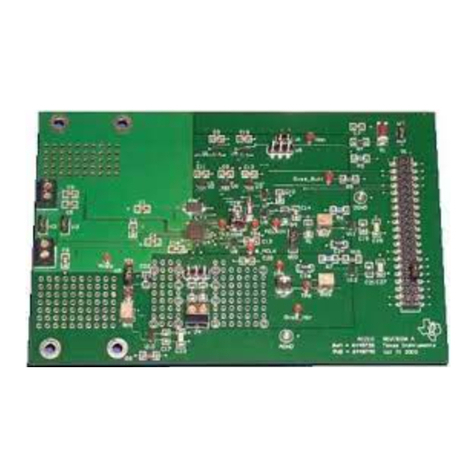
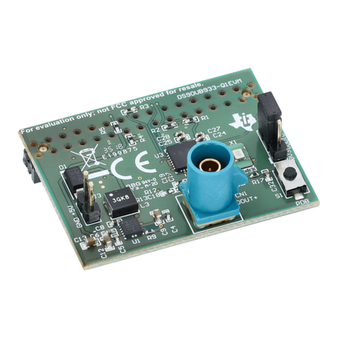
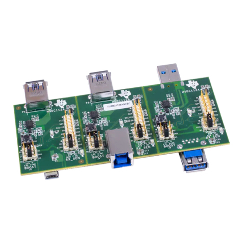
Figure 1-1. LM61460EVM Front.................................................................................................................................................. 1
Figure 1-2. LM61460EVM Angle................................................................................................................................................. 1
Figure 1-1. LM61460-Q1 Pin Configuration (Top View)...............................................................................................................4
Figure 1-2. LM61460-Q1 Schematic............................................................................................................................................4
Figure 2-1. Top View of LM61460-Q1 EVM................................................................................................................................. 6
Figure 4-1. LM61460-AS-400K Rev A EVM Schematic.............................................................................................................. 9
Figure 5-1. Top 3D View.............................................................................................................................................................11
Figure 5-2. Top Layer.................................................................................................................................................................11
Figure 5-3. Signal Layer 1 - Ground Plane................................................................................................................................ 11
Figure 5-4. Signal Layer 2 - Routing.......................................................................................................................................... 11
Figure 5-5. Bottom Layer........................................................................................................................................................... 12
Figure 5-6. Bottom 3D view....................................................................................................................................................... 12
Figure 6-1. Conducted EMI Measurement with CISPR 25 Class 5 Limit Lines (150 kHz to 30 MHz)....................................... 13
Figure 6-2. Conducted EMI Measurement with CISPR 25 Class 5 Limit Lines (30 MHz to 110 MHz)...................................... 13
Figure 6-3. Radiated EMI Measurement with Horizontal Bicon Antenna Under CISPR 25 Class 5 Limits............................... 13
Figure 6-4. Radiated EMI Measurement with Vertical Bicon Antenna Under CISPR 25 Class 5 Limits....................................13
Figure 6-5. Radiated EMI Measurement with Horizontal Log Antenna Under CISPR 25 Class 5 Limits.................................. 14
Figure 6-6. Radiated EMI Measurement with Vertical Log Antenna Under CISPR 25 Class 5 Limits.......................................14
Figure 6-7. Radiated EMI Measurement with Rod Antenna Under CISPR 25 Class 5 Limits................................................... 14
Figure 6-8. FSW = 400 kHz, 5 VOUT, Auto Mode.......................................................................................................................14
Figure 6-9. FSW = 400 kHz, 5 VOUT, FPWM Mode................................................................................................................... 14
Figure 6-10. FSW = 400 kHz, 3.3 VOUT, Auto Mode..................................................................................................................15
Figure 6-11. FSW = 400 kHz, 3.3 VOUT, FPWM Mode.............................................................................................................. 15
Figure 6-12. FSW = 2.2 MHz, 5 VOUT, Auto Mode.................................................................................................................... 15
Figure 6-13. FSW = 2.2 MHz, 5 VOUT, FPWM Mode.................................................................................................................15
Figure 6-14. FSW = 2.2 MHz, 3.3 VOUT, Auto Mode................................................................................................................. 15
Figure 6-15. FSW = 2.2 MHz, 3.3 VOUT, FPWM Mode..............................................................................................................15
Figure 6-16. FSW = 400 kHz, 5 VOUT, Auto Mode.....................................................................................................................16
Figure 6-17. FSW = 400 kHz, 5 VOUT, FPWM Mode................................................................................................................. 16
Figure 6-18. FSW = 400 kHz, 3.3 VOUT, Auto Mode..................................................................................................................16
Figure 6-19. FSW = 400 kHz, 3.3 VOUT, FPWM Mode.............................................................................................................. 16
Figure 6-20. FSW = 2.2 MHz, 5 VOUT, Auto Mode.................................................................................................................... 16
Figure 6-21. FSW = 2.2 MHz, 5 VOUT, FPWM Mode.................................................................................................................16
Figure 6-22. FSW = 2.2 MHz, 3.3 VOUT, Auto Mode................................................................................................................. 17
Figure 6-23. FSW = 2.2 MHz, 3.3 VOUT, FPWM Mode..............................................................................................................17
List of Tables
Table 1-1. Device and Package Configurations...........................................................................................................................1
Table 1-1. EVM Variants.............................................................................................................................................................. 5
Table 4-1. Different BOM Configurations................................................................................................................................... 10
Table 7-1. LM61460EVM-xS-400K Rev A EVM Bill of Materials............................................................................................... 18
Trademarks
Hotrod™ is a trademark of Texas Instruments.
Table of Contents www.ti.com
2LM61460-Q1 EVM User's Guide SNVU621D – MAY 2019 – REVISED JULY 2021
Submit Document Feedback
Copyright © 2021 Texas Instruments Incorporated
