User’s Guide
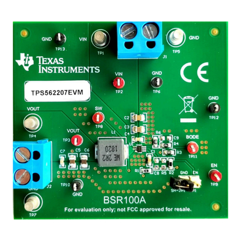
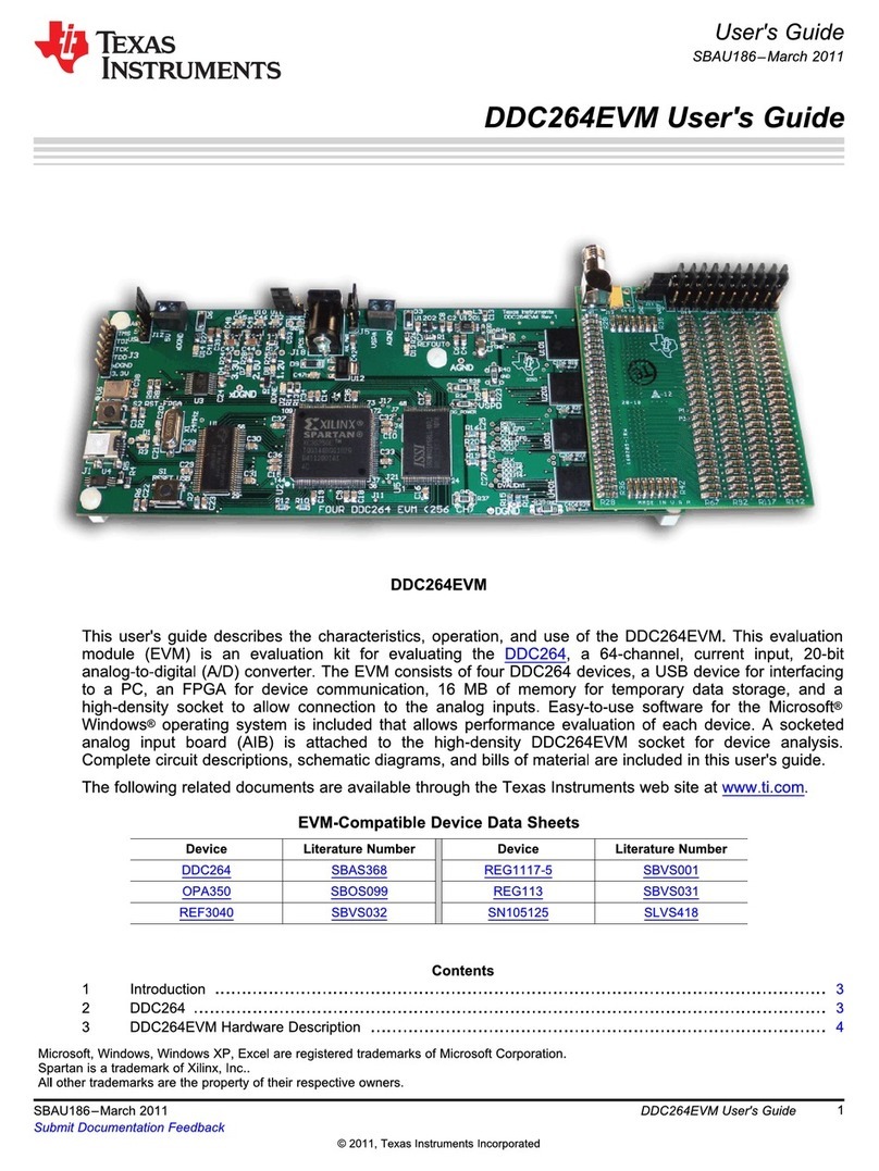
TPS36Q1EVM Voltage Supervisor User Guide
ABSTRACT
This user’s guide describes the TPS36Q1EVM evaluation module (EVM). This guide contains the EVM
schematic, bill of materials (BOM), assembly drawing and top and bottom board layouts.
Table of Contents
1 Trademarks..............................................................................................................................................................................2
2 Introduction.............................................................................................................................................................................3
2.1 Related Documentation......................................................................................................................................................4
3 Schematic, Bill of Materials, and Layout.............................................................................................................................. 5
3.1 TPS36Q1EVM Schematic..................................................................................................................................................6
3.2 TPS36Q1EVM Bill of Materials.......................................................................................................................................... 7
3.3 Layout and Component Placement....................................................................................................................................8
4 EVM Connectors................................................................................................................................................................... 10
4.1 EVM Jumpers...................................................................................................................................................................10
4.2 EVM Test Points...............................................................................................................................................................12
5 EVM Setup and Operation....................................................................................................................................................14
5.1 Input Power (VDD)............................................................................................................................................................ 14
5.2 RESET ............................................................................................................................................................................ 14
5.3 Manual Reset (MR).......................................................................................................................................................... 14
5.4 SET0 and SET1............................................................................................................................................................... 14
5.5 Watchdog Enable (WD_EN).............................................................................................................................................14
5.6 Watchdog Input (WDI)......................................................................................................................................................14
5.7 Watchdog Output (WDO)................................................................................................................................................. 14
5.8 CRST................................................................................................................................................................................14
5.9 CWD.................................................................................................................................................................................15
6 EVM Performance Results................................................................................................................................................... 16
7 Revision History................................................................................................................................................................... 17
List of Figures
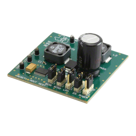
Figure 2-1. TPS36Q1EVM Board Top......................................................................................................................................... 3
Figure 2-2. TPS36Q1EVM Board Bottom....................................................................................................................................3
Figure 3-1. TPS36Q1EVM Schematic......................................................................................................................................... 6
Figure 3-2. Component Placement—Top Assembly....................................................................................................................8
Figure 3-3. Component Placement—Bottom Assembly.............................................................................................................. 8
Figure 3-4. Layout—Top.............................................................................................................................................................. 8
Figure 3-5. Layout—Bottom.........................................................................................................................................................8
Figure 3-6. Top Layer...................................................................................................................................................................8
Figure 3-7. Bottom Layer............................................................................................................................................................. 8
Figure 3-8. Top Solder Mask........................................................................................................................................................9
Figure 4-1. Schematic Closeup................................................................................................................................................. 13
Figure 6-1. Early Fault............................................................................................................................................................... 16
Figure 6-2. Late Fault................................................................................................................................................................ 16
Figure 6-3. Valid Pulse...............................................................................................................................................................17
Figure 6-4. Startup Delay...........................................................................................................................................................17
List of Tables
Table 2-1. Voltage Supervisors.................................................................................................................................................... 3
Table 3-1. BOM............................................................................................................................................................................7
Table 4-1. Pinout A Onboard Jumpers.......................................................................................................................................10
Table 4-2. Pinout B Onboard Jumpers.......................................................................................................................................11
www.ti.com Table of Contents
SLVUCG9 – OCTOBER 2022
Submit Document Feedback
TPS36Q1EVM Voltage Supervisor User Guide 1
Copyright © 2022 Texas Instruments Incorporated
