Texecom Impaq S User manual

Installation Manual
Impaq S / Impaq SC
INS877-1

INS877-1 2/20
Content
1.0 Introduction 3 ............................................................................................................................
1.1 Impaq S 3 ...............................................................................................................................
1.2 Impaq SC 5 .............................................................................................................................
2.0 Mounting 7 ..................................................................................................................................
2.1 Device mounting 7 .................................................................................................................
2.2 Magnet mounting (type SC only) 10 .......................................................................................
3.0 Wiring configuration 13 ............................................................................................................
3.1 End of Line (EOL) configuration 14 .........................................................................................
3.2 Connections 16 .......................................................................................................................
3.3 Connections - Impaq SC only 16 .............................................................................................
3.4 Optional wiring 16 ..................................................................................................................
4.0 LED functionality 16 ..................................................................................................................
5.0 Setting the shock sensitivity 17 ..............................................................................................
6.0 Specifications 18 ........................................................................................................................
7.0 Legal Information 19 .................................................................................................................

INS877-1 3/20
1.0 Introduction
The Impaq S is a wired shock sensor and the Impaq SC is a wired shock sensor with
the option for a magnetic contact.
Sections 1.1 and 1.2 show the key parts of the devices.
1.1 Impaq S

INS877-1 4/20

INS877-1 5/20
Icon Item
A LED function select DIP switch
B Sensitivity selection button
C Alarm resistance value selection DIP switch
D Tamper resistance value selection DIP switch
E Input terminal block
1.2 Impaq SC

INS877-1 6/20

INS877-1 7/20
Icon Item
A LED function select DIP switch
B Sensitivity selection button
C Magnet sensor
D Alarm resistance value selection DIP switch
E Tamper resistance value selection DIP switch
F Input terminal block
2.0 Mounting
2.1 Device mounting
Select the intended mounting position. The device can be installed in any
mounting orientation.
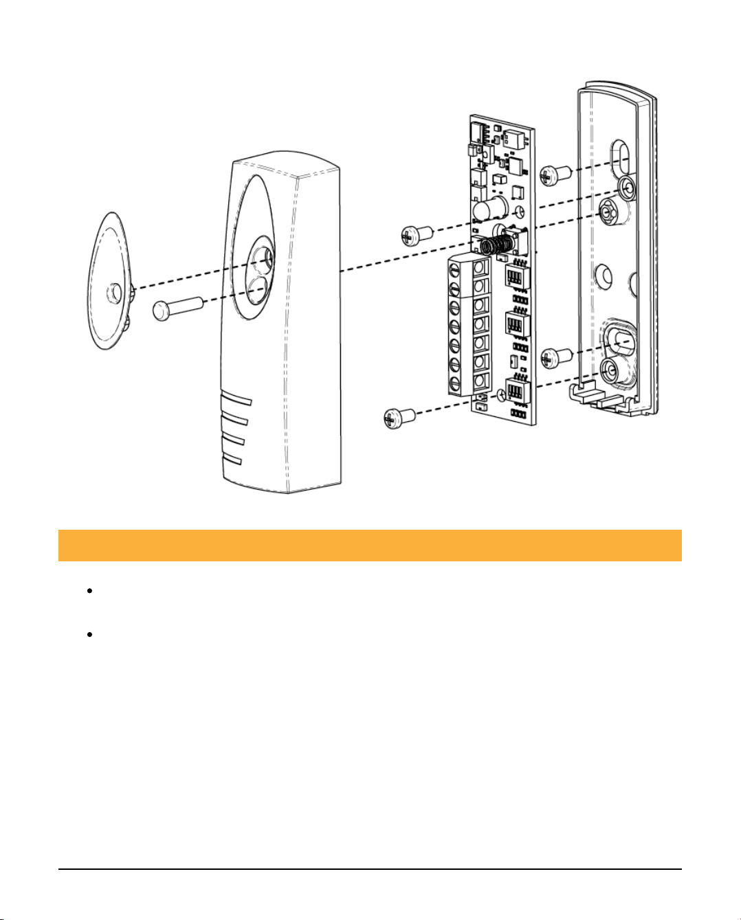
Open the device cover and remove the PCB using a screwdriver (see figure 1)
Remove the cable knockouts (see figure 2)
To ensure product compliance with EN50131, fix the base onto the
mounting surface (see figure 3) using the following screw type:
Head Type: Counter Sunk flat head
Head Diameter: 5.3-6.8mm
Screw Diameter 2.9-3.2mm
Screw length: 15.8-24.5mm
NOTE 1: If the product is mounted on concrete suitable wall plugs should be used.
NOTE 2: If installing the Impaq SC the same screw types should be used to mount
the magnet.
Figure 1

INS877-1 8/20
Figure 2

INS877-1 9/20
Figure 3
INS877-1 10/20
2.2 Magnet mounting (type SC only)
Once the device has been mounted, position the magnet so the notch is
aligned with the arrow marker on the PCB.
The magnet can be installed on either side of the device. Greater sensitivity
is achieved by positioning the magnet so the notch is aligned with the arrow
(see figure 4 for magnet distances).
Figure 4

INS877-1 11/20
Axis Approach Min
(mm)
Removal Max
(mm)
Right
X 20 27
Y+ 6 7
Y- 4 6
Z+ 42 49
Z- 35 42

INS877-1 12/20
Left
X 35 42
Y+ 5 7
Y- 5 6
Z+ 43 46
Z- 35 40
Once the correct position has been located fix the magnet in place (see figure 5).
Figure 5

INS877-1 13/20
3.0 Wiring configuration

INS877-1 14/20
3.1 End of Line (EOL) configuration
For use as a shock sensor the device is only compatible with EOL panels that
support the resistor values specified in the table below.
If installing the Impaq SC, the magnetic contact operates on a normally closed
circuit.
This table is for the shock sensor only
Panel Support Texecom Cooper
Menvier Honeywell DSC
Alarm EOL 4k7 4k7 1k 5k6
Tamper EOL 2k2 2k2 1k 5k6
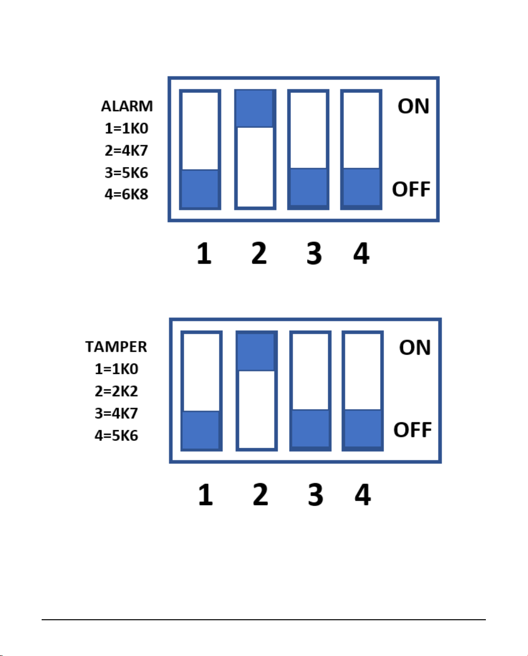
Select the correct resistance value for Tamper and Alarm by moving the DIP switch
to the ON position (Texecom values shown in example below).
INS877-1 15/20
NOTE: The product will only function if both DIP switches have a single switch set
to the ON position. If no switches or multiple switches are moved the product will
not function as expected.

INS877-1 16/20
3.2 Connections
Connect two wires into the 0V and 12V terminals to supply power to the
device from an EN50131 compliant power supply unit.
Connect two wires into the terminals marked EOL for the Alarm and Tamper
signals. These wires should be terminated into a zone on the intruder panel.
3.3 Connections - Impaq SC only
Connect two cores into the terminals marked MAG for the alarm signals from
the magnetic contact.
The shock and contact functions must be wired as two separate zones in the
panel.
3.4 Optional wiring
There is a facility to remotely enable the walk test LED from the panel. To use this
connect a wire from the RLED terminal to an output of the panel.
NOTE: This overrides the LED DIP Switch settings.
4.0 LED functionality
LED Colour Indication How to Select
Comfort Green every 6
seconds
Move switch 1 to
the ON position
Detection Red every time a
detection occurs
Move switch 2 to
the ON position
Example selection shown here:

INS877-1 17/20
NOTE: Any selections made on the comfort and detection LED switches will be
overridden when the RLED function is utilised.
5.0 Setting the shock sensitivity
After powering up the device single press the sensitivity button and the LED
will flash blue defaulting to sensitivity setting 2. There are 5 sensitivity
settings from 1 to 5 with 1 being the least sensitive (slowest flash rate) and 5
the most sensitive. Each press of the button will change the sensitivity
indicated by the flash rate of the blue LED, cycling from slow to fast and
finally back to slow after 5 presses.

INS877-1 18/20
Recommended Sensitivity Setting* Material Radius
1 Wood 1m
2 Framed Glass Window 1m
5 Concrete 0.5m
Before testing the device, press and hold the button (3 secs) to set the
desired sensitivity setting.
The LED will turn green for confirmation at which point the device is ready for
impact testing.
On impact test, if the LED turns red, the selected sensitivity setting is
appropriate for the installation.
If the LED turns orange the selected sensitivity setting is too high for the
installation.
If the LED turns green the selected sensitivity setting is too low for the
installation.
Select the next sensitivity level and repeat the test. Continue until a level is
selected whereby the device LED turns red on impact.
*Based on the testing requirements of EN50131-2-8 : 2016
6.0 Specifications
Specifications
Alarm System
EN50131-2-8:2017, EN50131-2-6:2008 (Impaq SC only)
EN50131-1:2006+A2:2017, PD6662:2017, Grade 2
Class II
Operating Voltage 9-16V DC
Maximum Current 15.4mA
Quiescent Current 12.8mA
Relative Humidity 0 - 95% non-condensing

INS877-1 19/20
Specifications
Operating Temperature -10°C to 55°C
Weight 80g
Dimensions 86mm x 25mm x 21mm (magnet 57mm x 11.5mm)
7.0 Legal Information
Supplier: Texecom Ltd, Haslingden, Lancashire, BB4 4PW, UK.
Made in England
WEEE Directive: 2012/19/EU (WEEE Directive): Products marked with this symbol
cannot be disposed of as unsorted municipal waste in the European Union. To
recycle, return this product to your local supplier upon the purchase of equivalent
new equipment, or dispose of it at designated collection points. For more
information see: www.recyclethis.info.
Maintenance: Test yearly by the installer.
Warranty: 2 year replacement warranty.
As the Impaq S/SC is not a complete alarm system, but only a part thereof,
Texecom cannot accept responsibility or liability for any damages whatsoever
based on a claim that the Impaq S/SC failed to function correctly. Due to our policy
of continuous improvement Texecom reserves the right to change specification
without prior notice.
Domestic Use: If this product is installed within reach of children the screw cover
should not be fitted as this could cause a choking hazard.
Hereby, Texecom declares that the equipment type : AEJA0000 (Impaq S),
AEKA000 and (Impaq SC), is in compliance with the Electo-magnetic Compatibility
(EMC) Directive 2014/30/EU.
The full EU declaration of conformity is available here: Impaq S, Impaq SC.

INS877-1 20/20
Certified by Telefication B.V.
Other manuals for Impaq S
1
This manual suits for next models
1
Table of contents
Other Texecom Accessories manuals


Popular Accessories manuals by other brands


turck
turck RU130U-M18E-LI8X2-H1151 quick start guide

Omnicom
Omnicom LLS-Ex 5 manual

CONVUM
CONVUM MPS-P35 quick start guide

GefenTV
GefenTV GTV-VOLCONT- D user manual

Jalousie-Welt
Jalousie-Welt Jupiter Operations and Maintenance, Instructions of shipment, unpacking and installation

Schlage
Schlage B008Q5CTTG Setup and Signals


