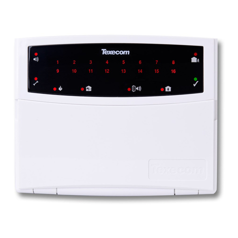
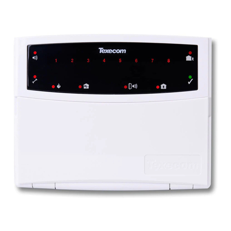
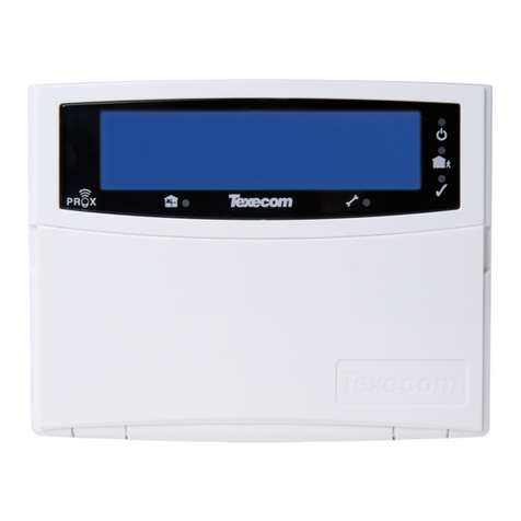
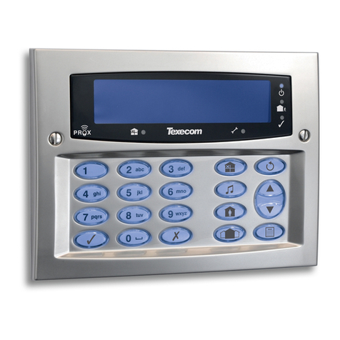
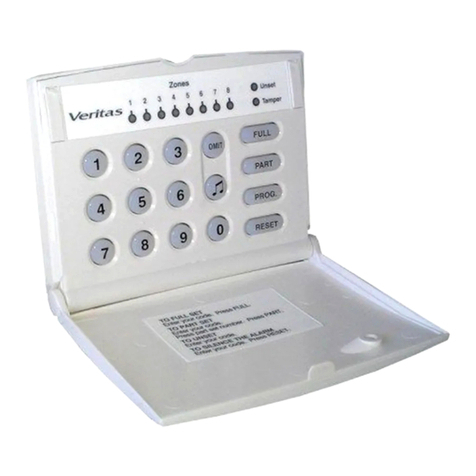
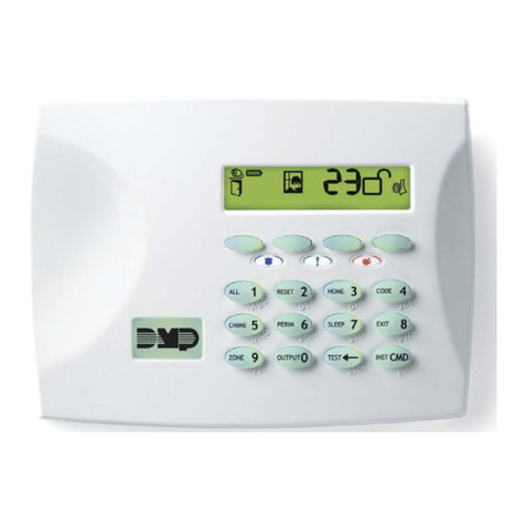
Texecom Premier RKP4 User manual

Installation Manual
PREMIER RKP4/8/16
&RKP8PLUS/16PLUS
INS181-4

INS181-4 2/9
Content
1.0 Installation 3 ..............................................................................................................................
1.1 Mounting RKP8/16 Plus 3 ........................................................................................................
1.2 Mounting RKP4/8/16 3 ............................................................................................................
1.3 Selecting an Address 5 ...........................................................................................................
1.4 Cable Entry RKP4/8/16 5 .........................................................................................................
1.5 Wiring 7 ..................................................................................................................................
1.6 Programming/Confirm Devices 7 ............................................................................................
1.7 Technical Specifications 8 ......................................................................................................
1.8 Standards 9 ............................................................................................................................
1.9 Warranty 9 .............................................................................................................................

INS181-4 3/9
1.0 Installation
The Premier RKP4/8/16 &8/16 Plus remote keypads are suitable for use with the following Texecom control panels: Premier 412 and Premier 816 with Version 2.1
or higher panel software. Up to 6 keypads may be connected to the system
1.1 Mounting RKP8/16 Plus
Open the keypad by carefully inserting a small flat-blade screwdriver into each slot at the base of the unit. Gently push the screwdriver to ease the retaining clips
upward, DO NOT LEVER OR TWIST. Excessive force is NOT required. The front flap and front cover can now be removed.
1.2 Mounting RKP4/8/16
Open the keypad by carefully inserting a small flat-blade screwdriver into both screw covers.
The PCB assembly is hinged for easy access. Alternatively the PCB assembly can be unclipped and completely removed if required.
Mount the keypad using at least two appropriate countersunk screws (no larger than No. 6). A keyhole slot has been provided to assist mounting and aid levelling.

INS181-4 4/9

INS181-4 5/9
1.3 Selecting an Address
Each keypad MUST be given a different address using the DIP switch on the left hand side of the PCB as follows:
N NEVER set two RKPs to the same address. Keypads are factory set to Address 1 (all switches off).
1.4 Cable Entry RKP4/8/16

INS181-4 6/9
Cable entry MUST use either the top left-hand hole or the cable channel.
NEVER run cables behind the PCB.

INS181-4 7/9
1.5 Wiring
It is strongly recommended that the system is completely powered down (mains and battery) before wiring a keypad. Connect the keypad to the control panel using
4-core cable as follows:
Up to six keypads may be connected in parallel (‘star’) or series (‘daisy‑chain’) or any combination.
N When using long cable runs or connecting keypads in series (‘daisy‑chain’) ensure that the voltage at the keypad is no less than 10.0V. When using 6-core or 8-core
cable always use the spare cores to ‘double-up’ on 0V. This will allow longer cable runs particularly when connecting keypads in series (‘daisy‑chain’). As a rule ‘trebling‑up’ on 0V
will be more beneficial than ‘doubling-up’ on 12V and 0V.
Keypad Zones
The Premier RKP8/16 Plus has two fully programmable zone inputs (Z1 COM Z2). For information on wiring configuration options please refer to the Premier
412/816 Installation Manual.
In order to use the keypad zones, you must first enable the zones using Menu 43 Option 1 (refer to the Premier 412/816 Installation Manual). When a keypad has its
zones enabled they are mapped onto the system as shown:
1.6 Programming/Confirm Devices
When the system is powered up you will need to confirm the devices connected to the data bus.
To Confirm Devices on all types of RKP’s panel firmware version 14.06 onwards please use the following procedures. The method for each keypad is detailed.
N For previous versions (14.04 and below) you can only confirm devices with an LCD RKP.

INS181-4 8/9
LED RKP 4, 8 & 16
Allow system to operate for 30 seconds1.
Enter installer/engineer code – would display confirm devices2.
Press Arm Key – Enter confirm devices menu (Top line of LED’s will illuminate)3.
Press Arm Key – Accept Detected network devices (All zone LED’s will un-illuminate)4.
Press Arm Key – Confirm detected devices, exit installer menu and returns to day mode operation5.
RKP+8
Allow system to operate for 30 seconds1.
Enter installer/engineer code – would display confirm devices2.
Press Yes Key – Enter confirm devices menu (All zone LED’s will illuminate)3.
Press Yes Key – Accept Detected network devices (All zone LED’s will un-illuminate)4.
Press Yes Key – Confirm detected devices, exit installer menu and returns to day mode operation5.
RKP+16
Allow system to operate for 30 seconds1.
Enter installer/engineer code – would display confirm devices2.
Press Yes Key – Enter confirm devices menu (All zone LED’s will illuminate)3.
Press Yes Key – Accept Detected network devices (All zone LED’s will un-illuminate)4.
Press Yes Key – Confirm detected devices, exit installer menu and returns to day mode operation5.
N Any premier International panels containing a software version prior to V14.02 that is flashed with version V14.02 or later, The Confirm Devices strings
are not loaded in the panel’s memory so any reference to them results in black squares being shown.
Reload English Text Strings
This can be achieved by entering the Installers code and then pressing the keypad’s “Menu” key this provides a short cut to the language
setting menu. Once the selected language is transferred from flash to memory the Confirm Devices strings will be displayed.
N Updated versions of the panel firmware can be found on our FTP server, or by contacting Technical Support.
1.7 Technical Specifications
Operating Voltage: 9 – 13.7VDC
Current Consumption: Nominal: 35mA; When fully back lit: 85mA
Zone Indicators: 16 on the RKP16/Plus; 8 on the RKP8/Plus 4 on RKP4
Status Indicators: RKP Plus Alarm: Red; Service: Yellow; Fire: Red; Bypass/Omit: Red; Instant:
Red; Stay/Part: Red; Ready: Green; Armed: Red
Status Indicators: RKP4/8/16 Alarm: Red; Trouble: Yellow; Armed: Red; Ready: Green
Data Bus: 4-wire up to 250m Star, Daisy-Chain or any combination
Operating Temperature: -10°C to +45°C
Storage Temperature: -20°C to +60°C
Maximum Humidity: 95% non-condensing
INS181-4 9/9
EMC Environment: Residential/Commercial/Light Industrial or Industrial
Material: 3mm Polycarbonate
Dimensions: RKP Plus 140mm x 115mm x 30mm
Dimensions: RKP4/8/16 140mm x 105mm x 35mm
Packed Weight: RKP4/8/16 380g
Packed Weight: RKP Plus 260g Approx.
1.8 Standards
2004/108/EC (CE directive): Hereby, Texecom declares that this device
is in compliance with the essential requirements and other relevant
provisions of Directive 2004/108/EC.
Weee Directive: 2002/96/EC (WEEE directive): Products marked with
this symbol cannot be disposed of as unsorted municipal waste in the
European Union. For proper recycling, return this product to your local
supplier upon the purchase of equivalent new equipment, or dispose of it
at designated collection points. For more information see:
www.recyclethis.info.
RoHs Directive: 2002/95/EC RoHS Compliant. Hereby, Texecom declares that this device does not
contain lead, mercury, cadmium, hexavalent chromium, polybrominated biphenyls (PBB) or
polybrominated depheny ethers (PBDE) in more than the percentage specified by EU directive
2002/95/EC, except exemptions stated in EU directive 2002/95/EC annex.
This product Type B Moveable device. And is suitable for use in systems designed to comply with
EN 50131-1 & EN50131-3 at Grade 2 and Environmental Class II.
1.9 Warranty
All Texecom products are designed for reliable, trouble-free operation. Quality is carefully monitored by extensive computerised testing. As a
result the Premier RKP8/16 Plus is covered by a two year warranty against defects in material or workmanship (details on request).
As the Premier RKP8/16 Plus is not a complete alarm system but only a part thereof, Texecom cannot accept responsibility or liability for any
damages whatsoever based on a claim that the Premier RKP8/16 Plus failed to function correctly. Due to our policy of continuous improvement
Texecom reserve the right to change specification without prior notice.
© Texecom Ltd 2011.
© Texecom Ltd 2011.
This manual suits for next models
4
Table of contents
Other Texecom Keypad manuals

Texecom
Texecom PREMIER RKP8PLUS User manual

Texecom
Texecom Veritas Excel Master User manual

Texecom
Texecom Premier Elite LCDLP-W User manual

Texecom
Texecom Premier RKP8 Plus User manual

Texecom
Texecom Premier LCDLP User manual

Texecom
Texecom Premier RKP8 User manual

Texecom
Texecom Premier Series Instruction and safety manual

Texecom
Texecom Premier LCDLP User manual

Texecom
Texecom Veritas RKP User manual

Texecom
Texecom Premier Elite Series User manual