Texecom Premier Elite 5Ci-W User manual
Premier Elite 5Ci-W
Installation Manual
INS655-3
Premier Elite 5Ci-W Internal Installation Manual
2 INS655-3
Introduction
The Premier Elite 5Ci-W sounder is an Internal warning device with Ricochet®mesh technology. It is now even easier to add an internal
wireless sounder to your security system. As the device is self powered the only limit on the number of units you can put on a system is
determined by how many free Ricochet enabled zones you have available.
This unit is NOT designed for external applications.
Tamper Detection
As this unit is designed for internal applications only, and may be mounted at low level and within easy reach the SAB facility has been
disabled and the unit WILL NOT self activate in the case of the device being tampered.
System Compatibility
The Premier Elite 5Ci-W is compatible with all Premier Elite control panels V2.11 and later, and Premier Elite 8XP-W & Premier Elite
32XP-W. Ricochet Monitor V2.18.2 or later should also be used.
Battery Pack
The battery pack is retained by a reusable cable tie. and should be secured through the holes in the backplate above the Piezo module.
All eight batteries (supplied) must be installed with the correct polarity. Failure to do so will result in the device reporting a
battery fault. If 1-2 batteries are incorrectly fitted the firmware will detect this on power up and flash both comfort LED’s for
approximately 10 minutes. While the unit is in this state it will not learn to a panel. After approximately 10 minutes the unit will
power off in order to save energy.
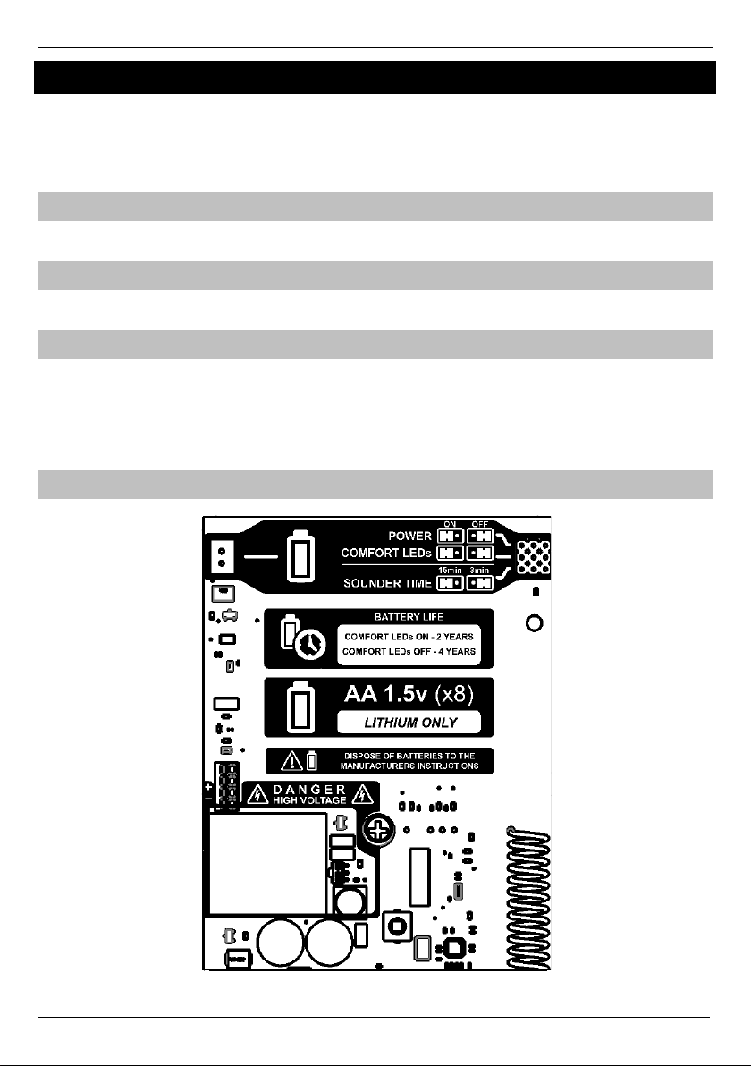
PCB Layout

Premier Elite 5Ci-W Internal Installation Manual
INS655-3 3
Symbol
Description
The battery pack should be connected here after installing the batteries.
Powering the sounder on for the first time starts the learn process. Once learned the "POWER"
jumper should be left in the "ON" position.
If you need to relearn the sounder, the link should be moved to the OFF position for a minimum of
1 second.
Enables or disables the comfort LED's. Disabling the LED's significantly increases battery life.
The sounder on time is dictated by this jumper position and is independent of the Bell On
time in the control panel. If however the panel bell time is shorter than the jumper setting
selected, the panel will over ride the jumper setting.
Only Lithium AA 1.5V Type batteries should be used
Alkaline batteries should not be used, they will have a much shorter lifespan and can freeze and
fail to operate at -5C
Used Batteries should be disposed of according to the manufacturers instructions.
The quoted battery life is an estimate and will depend on the site conditions.
Learning the Sounder
As with all Ricochet enabled devices, the sounder should be learned to the control panel along with all other devices BEFORE it is installed
in it's final location.
The Premier Elite 5Ci-W is learned to a Zone on the control panel in the same way that Ricochet enabled detection devices are. The Zone
type and Ricochet Device Mode is automatically assigned based on the type of device being learned. In the case of the sounder the Zone
Type is set to "Custom" and the Ricochet Device Mode is set to Device Specific. These should not be changed. Zone attributes 1 & 2 and
Chime options will be ignored for Ricochet enabled Sounders.
You can learn the device from first power up following "Confirm Devices" or from the dedicated Ricochet Learn menu.
The 5Ci-W has no Learn Switch, learning is initiated by connecting the batteries via the Power Jumper
To learn the 5Ci--W to the system follow the diagram below.
YES to Select:-
Learn Ricochet
yy
Learn Device?
Zone ??? N?,E??
Power up Device!
N?,E?,D?? - 20s
Learn Device to
Zone ??? N?,E??
yy
yy
yy
nnU
NN
If you need to delete the device from the system you should first put it into "hold off " mode and remove the batteries.
If the device will not learn to the system check that all batteries are installed correctly.

Premier Elite 5Ci-W Internal Installation Manual
4 INS655-3
LED Indications
The Premier Elite 5Ci-W LED’s aid in the installation of the device and act as status indicators. The table below details the status of each
LED indicator.
The LED jumper has no effect on the status described below.
Leds
Status
Left LED flashing quickly
Device is attempting to communicate with receiver after power up.
Left LED flashing slowly
Device has learnt or re-connected to receiver and is waiting for the tamper to be
closed.
Both LEDs off
Device has failed to learn or failed to communicate after tamper has been
closed.
Right LED flashing quickly
Device is attempting to communicate with receiver after tamper has been
closed.
Right LED on solid (for 3 seconds)
Device has successfully connected with receiver after tamper closed.
Right LED flashing slowly
Hold-off mode has been requested from the panel but the tamper is closed. Bell
will not self-activate. Cancels after 20 minutes.
LEDs alternating quickly.
Device has successfully connected with receiver after tamper closed and self-
activation on tamper will re-activate in 2 minutes.
Both LEDs flashing
1 or 2 batteries are fitted incorrectly. Remove the batteries and reinstall correctly.
Hold-Off Mode
For safety reasons, each Texecom sounder and strobe unit incorporates a unique patented engineer Hold-Off mode. This mode prevents
the unit from self-activating during installation and maintenance, thereby allowing only bona fide engineers access to the unit without any
loss of tamper protection. The sounder can be put in hold-off mode by flashing the strobe 3 times, or by pressing the Omit key when in Bell
Test menu.
When the outer cover is replaced and the tamper circuit is closed, the LEDs will alternate rapidly, confirming that the tamper circuit is secure
and signalling that self activation on tamper will be re-enabled within 2 minutes, after which the LEDs will alternate slowly to signal normal
operation. If the tamper circuit is re-opened within the 2 minute period, then hold-off mode will be restored.
The LED's will only flash after hold off mode has stopped IF the LED jumper is in the "ON" position.
The strobe is disabled during hold-off mode. Hold-off mode is immediately cancelled when the sounder is activated from the control panel if the
tamper is closed..
Tamper Detection
As this unit is designed for internal applications only and may be mounted at low level and within easy reach the SAB facility has been
disabled. The unit WILL NOT self activate in the case of the device being tampered.
Care should be taken when installing these devices, and all possible precautions should be taken to ensure the units are not easily
accessible to unauthorised persons.
Tamper signals will still be generated and logged by the control panel. Tamper signals will also be transmitted to the ARC if signalling is
enabled.
Mounting the Unit
Select a suitable position to mount the unit, which satisfies the following criteria:
Good wireless signal
The wireless signal may be checked before final installation by depressing the tamper switch briefly. The Right LED will flash to indicate
communication and will the go solid for 3 seconds to indicate a successful connection.
Highly prominent for maximum deterrence
High enough to be out of normal reach to deter tampering. See above
In addition to the corner screw fixing points, the unit also has a central keyhole to simplify mounting and aid levelling.
Four screws and wall plugs are required for mounting the backplate to an even surface.
An additional screw is required to provide "Removal from Mounting" tamper and is required in installations complying with the requirements PD6662
and/or EN50131. In doing so, care must be taken to leave the screw head slightly proud to ensure that the microswitch remains level and closes
correctly when the outer cover is fitted.

Premier Elite 5Ci-W Internal Installation Manual
INS655-3 5
Rear Tamper
A Screw must
be used here
Installing The Cover
Commissioning
Once the installation is complete the sounder should be tested to confirm correct operation. This can be achieved by utilising the
Bell/Strobe test facility in the "Engineer Utilities" menu.
Technical Specification
Environmental
Electrical
Volume
105dB Peak at 1m (A Weighting, 90)
Supply Voltage:
12V DC
Battery Type:
8 x Lithium type AA 1.5V
High Power LED Strobe:
320lm
Acoustic Output
Varying Sound Output
Flash Rate:
1Hz (typical)*
Cut-Off Time:
15 minutes or3 minutes(selectable)
Waterproof Coating:
Conformal
Comfort LEDs:
Environmental Protection
N/A
Brightness:
100mcd (typical)
Flash Rate (tamper
secure):
1/4 sec flash at 5 sec intervals alternating
(typical)
Wireless Frequency:
868.0MHz –868.6MHz
Operating Temperature:
-25C (-13F) to +55C (+131F)**
Storage Temperature:
-25C (-13F) to +60C (+140F)
EMC Environment:
Residential / Commercial /Light
Industrial / Industrial
* The flash rate will reduce to 0.125Hz after flashing for 20 minutes (1 flash every 8 seconds). This is a software feature to reduce power consumption and
cannot be disabled. After 10 days the strobe is cancelled completely. Turning the strobe off then on again will resume normal operation.
** In extreme conditions where the temperature is likely to exceed the stated maximum avoid direct sunlight.
Physical
Material
3mm polycarbonate
Packed Weight
835g (30oz) approx
Tamper Detection
Wall & Lid
Dimensions (h x w x d)
189 mm x 186 mm x 60 mm

Premier Elite 5Ci-W Internal Installation Manual
6 INS655-3
Standards
Texecom declares that this product complies with the requirements of the following directives:
1999/5/EC R&TTE Directive
2004/108/EC EMC Directive
2006/95/EC LVD Directive
2011/65/EU RoHS Directive
The product therefore meets all the requirements to enable it to be CE marked.
Weee Directive: 2012/19/EU (WEEE directive): Products marked with this symbol cannot be disposed of as unsorted municipal waste in the
European Union. For proper recycling, return this product to your local supplier upon the purchase of equivalent new equipment, or dispose
of it at designated collection points. For more information see: www.recyclethis.info.
This product is a Type B Moveable device and is suitable for use in systems designed to comply with EN 50131-4, EN50131-5-3 and PD6662 at Grade 2 and
Environmental Class II.
Security Grade 2 Environmental Class 2
EN Standard
Premier Elite 5Ci-W
EN60950-1
EN61000-6-3
EN 301 489-3
EN50130-4
EN300 220-1
EN50131-1
EN50130-5
EN50131-5-3
EN50131-6
PD6662
EN50131-4
Warranty
All Texecom products are designed for reliable, trouble-free operation. Quality is carefully monitored by extensive computerised testing. As a result the Premier Elite
5Ci-W is covered by a two year warranty against defects in material or workmanship (details on request).
Because the Premier Elite 5Ci-W is not a complete alarm systems but only a part thereof, Texecom cannot accept responsibility or liability for any damages whatsoever
based on a claim that a unit failed to function correctly. Due to our policy of continuous improvement Texecom reserve the right to change specification without prior
notice.
Premier & Premier Elite are trademarks of Texecom Ltd

Premier Elite 5Ci-W Internal Installation Manual
INS655-3 7
Notes:

Texecom Limited, Bradwood Court, St. Crispin Way, Haslingden, Lancashire BB4
4PW, England.
Technical Support:
UK Customers Tel: 08456 300 600
(Calls charged at 3.36 pence per minute from a BT landline. Calls from other networks may vary.)
International Customers Tel: +44 1706 233875
Email: techsupport@texe.com
© Texecom Limited 2015
INS655-3
Other manuals for Premier Elite 5Ci-W
1
Table of contents
Other Texecom Marine Equipment manuals

Texecom
Texecom Odyssey X User manual

Texecom
Texecom Premier Elite Odyssey-W Series User manual

Texecom
Texecom Premier Elite Odyssey 5-W User manual

Texecom
Texecom Premier Elite 5Ci-W User manual

Texecom
Texecom Premier Elite Odyssey 1-W User manual

Texecom
Texecom Flashguard User manual

Texecom
Texecom Odyssey X Series User manual


