TFT BlitzForce User manual
©Copyright Task Force Tips, Inc. 2006-2018 LIX-730 January 8, 2018 Rev08
MANUAL: BlitzForce
Portable Monitor
INSTRUCTIONS FOR SAFE OPERATION AND MAINTENANCE
DANGER Understand manual before use. Operation of this device without understanding the manual and
receiving proper training is a misuse of this equipment. Obtain safety information at www.tft.
com/serial-number
DANGER Risk of sliding increases at low elevation angles. To reduce risk of injury or death from sliding,
test safety elevation plunger before using.
This Instruction Manual is intended to familiarize fi refi ghters and maintenance personnel with the operation, servicing, and
safety procedures associated with the portable monitor.
This manual should be kept available to all operating and maintenance personnel.
TASK FORCE TIPS, INC.
MADE IN USA • www.tft.com
3701 Innovation Way, Valparaiso, IN 46383-9327 USA
800-348-2686 • 219-462-6161 • Fax 219-464-7155
DANGER
PERSONAL RESPONSIBILITY CODE
The member companies of FEMSA that provide emergency response
equipment and services want responders to know and understand the
following:
1. Firefi ghting and Emergency Response are inherently dangerous activities
requiring proper training in their hazards and the use of extreme caution
at all times.
2. It is your responsibility to read and understand any user’s instructions,
including purpose and limitations, provided with any piece of equipment
you may be called upon to use.
3. It is your responsibility to know that you have been properly trained in
Firefi ghting and /or Emergency Response and in the use, precautions, and
care of any equipment you may be called upon to use.
4. It is your responsibility to be in proper physical condition and to maintain
the personal skill level required to operate any equipment you may be
called upon to use.
5. It is your responsibility to know that your equipment is in operable
condition and has been maintained in accordance with the manufacturer’s
instructions.
6. Failure to follow these guidelines may result in death, burns or other
severe injury.
FEMSA
Fire and Emergency Manufacturers and Service Association
P.O. Box 147, Lynnfi eld, MA 01940 • www.FEMSA.org
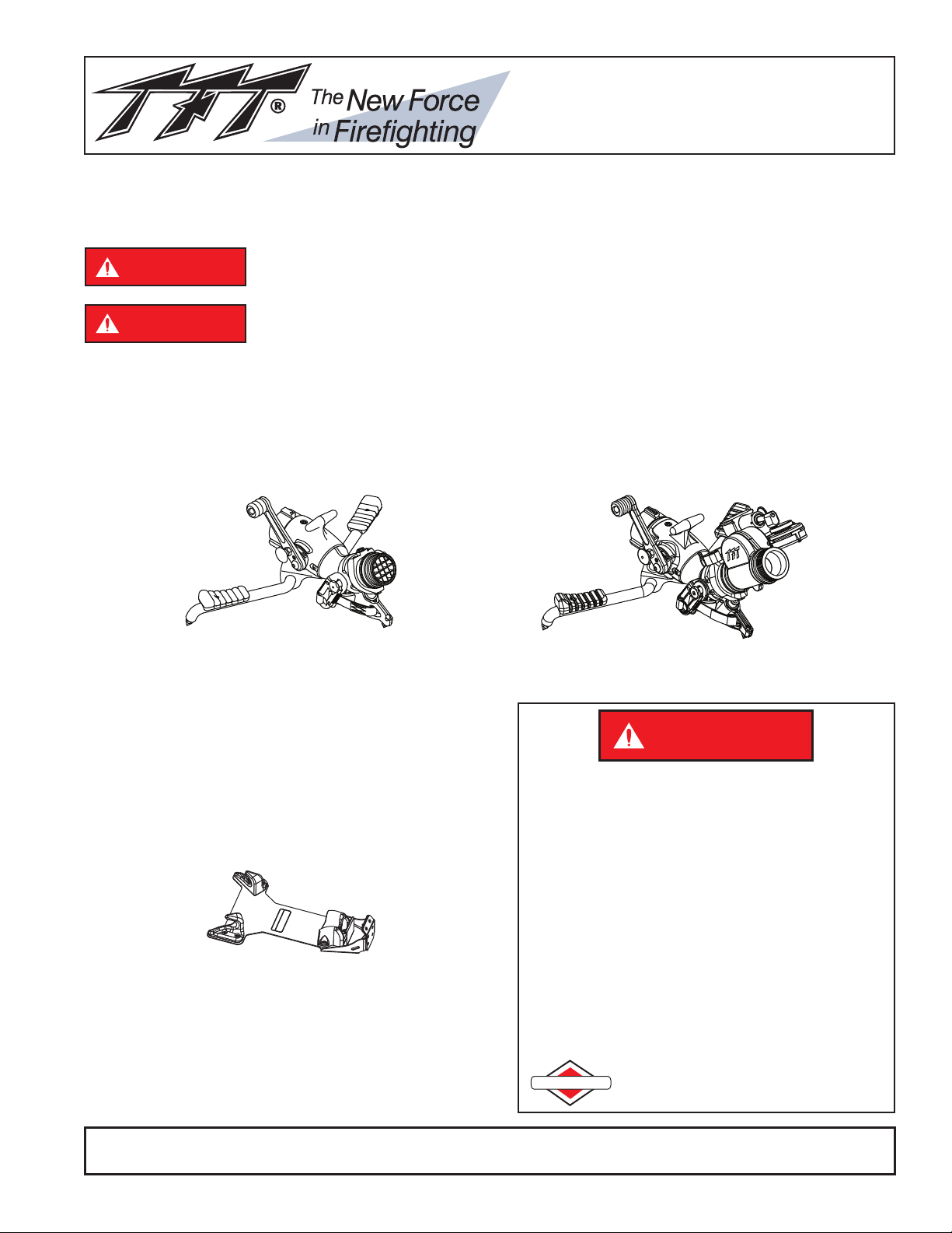
BlitzForce Portable Monitor BlitzForce OSC Portable Monitor
MAXIMUM OPERATION PRESSURE
175 PSI (12 bar)
MAXIMUM FLOW
500 GPM (2000l/min)
BlitzForce Mounting Bracket

©Copyright Task Force Tips, Inc. 2006-2018 LIX-730 January 8, 2018 Rev08
2
Table Of Contents
1.0 Meaning of Safety Signal Words
2.0 General Information
2.1 BlitzForce Part Identification
2.2 Valve Operation
2.3 Folding Legs
2.3.1 Carbide Spikes
2.4 Full-time Swivel Inlet Coupling
2.5 Outlet Pivots and Safety Elevation Plunger
2.5.1 Elevation Holding Mechanism
3.0 Flows and Pressures
3.1 Automatic, Fixed, and Selectable Flow Nozzles
3.2 Stacked Tips or Smoothbore Nozzles
3.3 Stream Straighteners
3.4 Use with Foam
3.5 Use with Salt Water
3.6 BlitzForce Portable Monitor Pressure Loss
4.0 Deployment of BlitzForce Portable Monitor
4.1 Carrying with an Uncharged Hose
4.2 Carrying with a Charged Hose
4.3 Pressure Gage Port
5.0 Anchoring
5.1 Anchoring by Weight
5.2 Anchoring by Spike Holds
5.3 Anchoring by Hooking Legs
5.4 Anchoring by Tying Off with Safety Strap
6.0 OSC Oscillating Unit
6.1 Safety - Oscillator
6.2 General - Oscillator
6.3 Oscillator
6.4 Oscillating Speed and Coverage
7.0 Storage
8.0 Exploded View and Parts List
8.1 BlitzForce Portable Monitor Exploded View and Parts List
8.2 BlitzForce Oscillator Exploded View
9.0 XXL-B Storage Bracket Installation Instructions
9.1 For Blind Mounting
9.2 For Mounting Where Back Of The Mounting Surface Is Accessible
9.3 Mounting Bracket Dimensions
10.0 Bracket Exploded View and Parts List
11.0 Warranty
12.0 Maintenance
12.1 Service Testing
12.1.1 Hydraulic Testing
12.1.2 Shut-off Valve Test
12.1.3 Records
12.2 Repair
13.0 Answers to Your Questions
14.0 Operation Checklist
©Copyright Task Force Tips, Inc. 2006-2018 LIX-730 January 8, 2018 Rev08
3
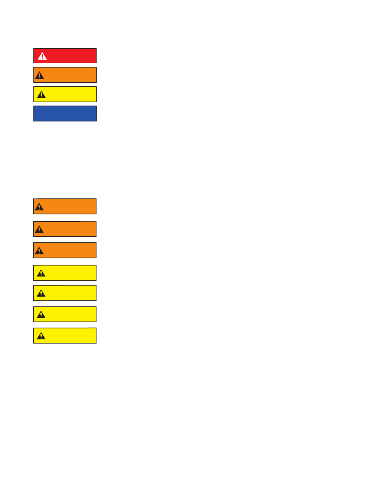
1.0 MEANING OF SAFETY SIGNAL WORDS
A safety related message is identifi ed by a safety alert symbol and a signal word to indicate the level of risk involved with a particular
hazard. Per ANSI standard Z535.6-2011, the defi nitions of the four signal words are as follows:
DANGER DANGER indicates a hazardous situation which, if not avoided, will result in death or serious
injury.
WARNING WARNING indicates a hazardous situation which, if not avoided, could result in death or serious
injury.
CAUTION CAUTION indicates a potentially hazardous situation which, if not avoided, could result in minor
or moderate injury.
NOTICE NOTICE is used to address practices not related to physical injury.
2.0 GENERAL INFORMATION
The BlitzForce Portable Monitor is an effi cient, compact and easy to maneuver portable monitor. The monitor is a lightweight aluminum
unit, which can deliver 500 GPM of water. This monitor can be mounted in a pre-connected state on the truck-mounting bracket for
achieving quick and eff ective initial attack. General product specifi cations are as follows:
• Standard Inlet Coupling: 2 ½ inch NH Female
• Standard Outlet: 2 ½ inch NH male
• Flow range: up to 500 GPM (2000 LPM)
• Maximum inlet pressure: 175 PSI (12 BAR)
• Vertical Stream Range: 20 to 60° above horizon manned
(30 to 60° above horizon unmanned)
• Horizontal Stream Range: +/- 20 degrees either side of centerline
• Size, legs folded: 14.8”L x 9.0”W x 9.4”H (375 x 230 x 240mm)
• Size, legs unfolded: 15”L x 25.8”W x 10”H (380 x 655 x 254mm)
• Weight: 15 lbs (6.9 kg)
WARNING This equipment is intended for use by trained personnel for fi refi ghting. Its use for other
purposes may involve hazards not addressed by this manual. Seek appropriate guidance and
training to reduce risk of injury.
WARNING An out of control monitor can cause injury or death. To reduce the risk of instability, do not
attempt to move the monitor with water fl owing.
WARNING The fl ow from the monitor may be vital to keep a fi refi ghter from injury or death. Avoid situations
that may interrupt fl ow to the monitor such as: hose line kinks, traffi c running over hose, and
automatic doors or devices that can pinch the hose.
CAUTION Master streams are powerful and capable of causing injury and property damage. Make sure
the monitor is pointing in a safe direction before water to the nozzle is turned on. Use care in
directing the stream.
CAUTION Monitor must be properly connected to hose and nozzle. Mismatched or damaged threads may
cause leaking or uncoupling under pressure and could cause injury.
CAUTION Do not couple aluminum to brass. Dissimilar metal coupled together can cause galvanic
corrosion that can result in inability to unscrew threads or complete loss of thread engagement.
CAUTION Use with salt water is permissible provided the monitor is thoroughly cleaned with fresh water
after each use. The service life of the monitor may be shortened due to the eff ects of corrosion
and is not covered under warranty.
©Copyright Task Force Tips, Inc. 2006-2018 LIX-730 January 8, 2018 Rev08
4
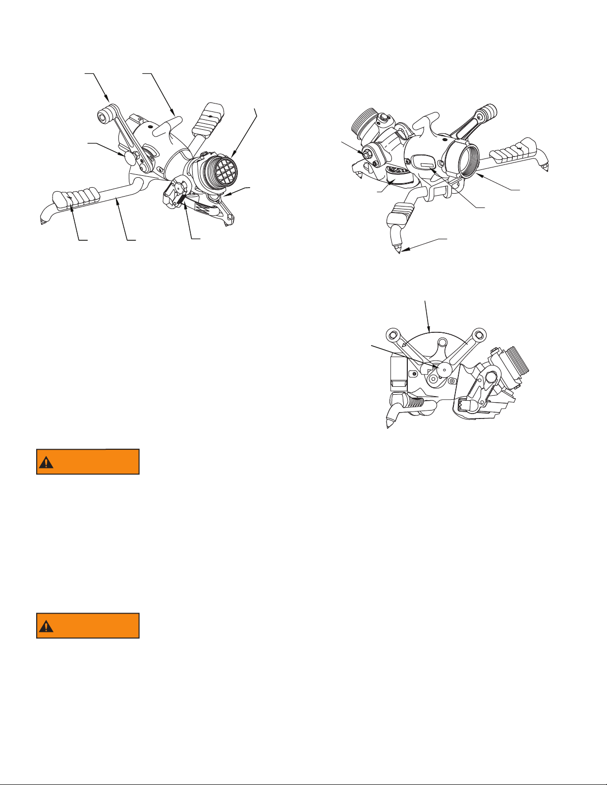
2.1 BlitzForce PART IDENTIFICATION
Figure 2.1 identifi es the various parts and controls of the Portable Monitor.
SEE SECTION 6
FOR BLITZ FORCE
OSCILLATORS
Pivoting Outlet
with Removable
Stream Straightener
Strap Hook
& Anchor
Handle
Locking
Knob
Valve
Handle
Folding
Leg
Carrying
Handle
Knee
Pad
Safety
Elevation
Plunger
Anchor Strap
Reel Assembly
Carbide Tipped Spike
Inlet
Serial
Number
Elevation
Holding
Mechanism
Figure 2.1 Portable Monitor Parts and Controls
2.2 VALVE OPERATION
The valve handle is locked in the closed position so that the
Portable Monitor may be carried/moved without the valve
inadvertently opening when water fl ow is not desired. To unlock
the valve handle from the closed position:
1. Pull knob on right side of valve handle.
2. While pulling on knob move valve handle slowly to an
open position with other hand.
As soon as valve is opened the knob may be released. Valve
handle may be moved to any position by pushing or pulling on
the valve handle. When the valve is closed the valve handle
automatically locks and must be unlocked again to reopen. The
monitor has a label that indicates the direction to open and close
the valve. The valve opening procedure is shown in fi gure 2.2.
Remember to close the valve slowly to reduce water hammer.
2) Open Valve
LOCKED
CLOSED
POSITION
ON
POSITION
1) Pull Knob
Away
From Handle
To Unlock
Figure 2.2 Valve Opening Procedure
WARNING Injury or death from an out of control monitor can occur. If monitor gets out of control, retreat
from monitor immediately. Do not attempt to regain control of monitor while it is fl owing.
To minimize the risk of an out of control monitor:
• Test Shut-off Valve before each use.
• Tie off the monitor when practical.
• Hook legs on stationary objects such as door frames,
cracks, sign posts etc.
• Keep elevation as high as practical.
• Choose surfaces that allow spikes to dig in.
• Assure that the hose is not lifting the spikes off the ground.
• Reduce fl ow to limit nozzle reaction if stability is questionable.
2.3 FOLDING LEGS
The Portable Monitor has two legs that fold for storage and unfold for operation. The legs are held in the folded and unfolded position
by spring detents. To fold or unfold the legs:
1. Grasp the spike end of one leg and pivot it to the folded or unfolded position.
2. Repeat for the other leg.
WARNING In the unfolded position the legs provide a stable base for operation of the monitor. Lack of
stability can cause an out of control monitor resulting in injury or death. Do not operate as a
portable monitor with either one or both legs in the folded position.
©Copyright Task Force Tips, Inc. 2006-2018 LIX-730 January 8, 2018 Rev08
5
2.3.1 CARBIDE SPIKES
The BlitzForce Portable Monitor has 3 tungsten carbide tipped spikes on the legs and the base to resist sliding by digging into the
surface the monitor is sitting on. The amount of sliding force these spikes can withstand depends upon the amount of downward and
sideways force that is on the base and the hardness and texture of the surface the spikes are in contact with. At low elevation angles,
it is diffi cult for these spikes to resist sliding. These spikes are essential to safe operation of the monitor and must be in contact with
the ground at all times. Set the monitor on an even surface so that all three spikes contact the ground. Replace any spike if the tip
diameter exceeds 1/16 inch (1.6 mm).
WARNING For stable operation the three spikes must maintain in contact with the ground. Do not place
the monitor on top of debris, objects, or uneven terrain that would keep any of the spikes from
contacting the ground.
WARNING On hard slippery surfaces the spikes may provide little resistance to sliding. In these cases the
monitor should be tied off or the legs hooked on stationary objects to keep the monitor in position.
Also, a person’s weight applied to the monitor may help increase resistance to sliding.
CAUTION Spikes must be sharp to provide resistance to sliding. Replace any spike if the tip diameter
exceeds 1/16 inch (1.6 mm).
CAUTION Spikes are sharp and exposed. Use care around spikes to avoid injury and damage to clothing
or other property.
2.4 FULL TIME SWIVEL INLET HOSE COUPLING
The BlitzForce Portable Monitor has a full-time swiveling inlet coupling so that when the hose is charged, any twist in the hose will
minimize the lifting of the spikes off the ground. The monitor is equipped with three spikes to provide traction when fl owing from the
ground. For the spikes to provide traction they must remain in contact with the ground. Assure that the hose is not on top of anything
that would cause the spikes to be lifed off the ground.
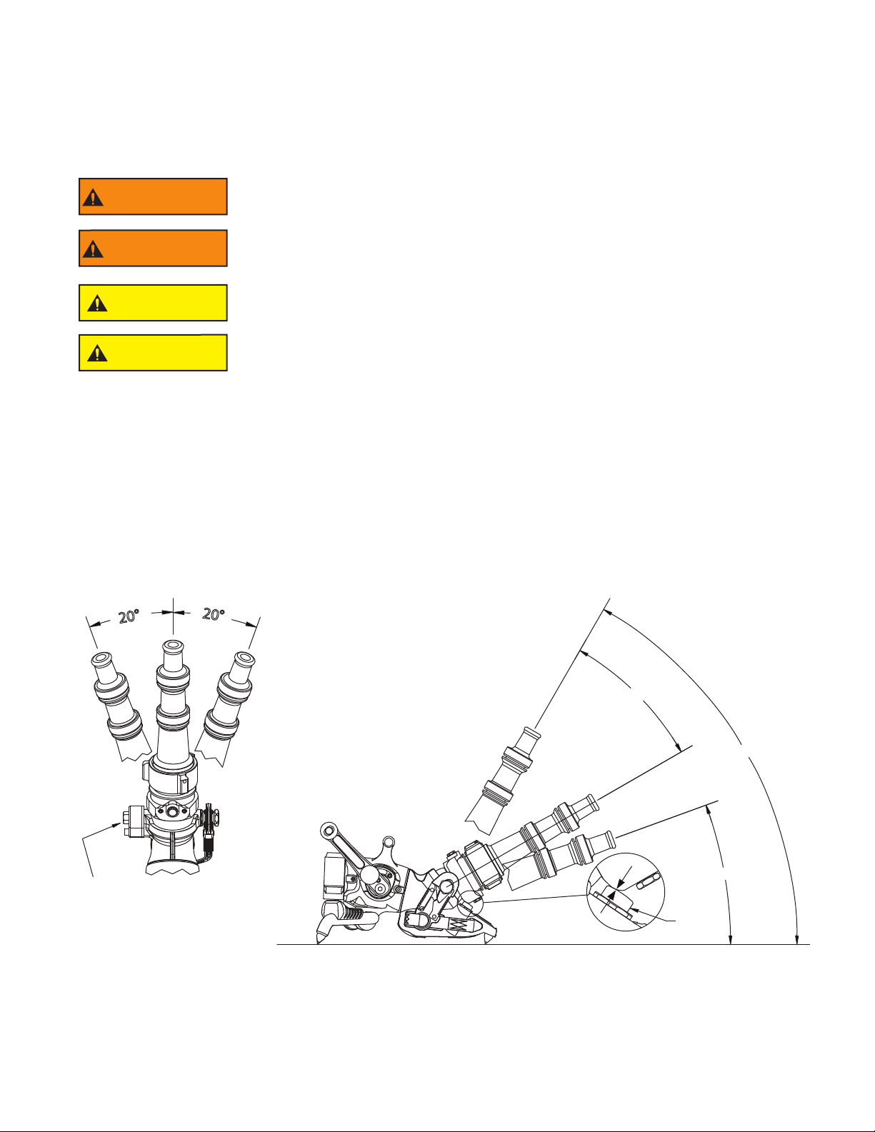
2.5 OUTLET PIVOTS AND SAFETY ELEVATION PLUNGER
The monitor’s outlet pivots allow for 20 degrees of horizontal rotation either side of center. The elevation range is from 20 to 60
degrees manned and 30 to 60 degrees unmanned. (30 to 50 degrees with the oscillator version) While manned, to lower the outlet
below the 30 degrees elevation, just push down the outlet to the desired elevation. Below the outlet pivot is a spring-loaded plunger
that returns the outlet to 30 degrees if the operator releases on the outlet or the monitor is unmanned. The pivots are easy to
reposition under pressure and are good for rapid redirecting of the stream. Figure 2.5 shows the outlet pivots range of motion.
Elevation drag adjusting nut.
Tighten to increase drag.
Loosen to decrease drag.
Do not exceed 200 in-lb
(22 N-M) of holding torque.
20°
20°
20° MIN
60° MAX
10° MANNED
30° UNMANNED
Safety
Elevation
Plunger
3X zoom
SIDE VIEW
Figure 2.5 Outlet Pivot Range of Motion
This manual suits for next models
1
Table of contents
Popular Safety Equipment manuals by other brands

Lanex
Lanex PB-20 instruction manual

SKYLOTEC
SKYLOTEC ANCHOR ROPES Instructions for use

Besto
Besto Buoyancy Aid 50N Instructions for use

TEUFELBERGER
TEUFELBERGER NODUS Manufacturer's information and instructions for use

Troy Lee Designs
Troy Lee Designs Tbone Product owners manual

Innova
Innova Xtirpa Instruction and safety manual

bolle SAFETY
bolle SAFETY B810 quick start guide

SHENZHEN FANHAI SANJIANG ELECTRONICS
SHENZHEN FANHAI SANJIANG ELECTRONICS A9060T instruction manual

Hiltron security
Hiltron security POWER8E Installation and use manual

Salewa
Salewa MTN SPIKE user manual

Hatco
Hatco B-950P installation guide

Sitec
Sitec TX MATIC operating manual


