TGW NBC Instruction manual

Installation, Operation, Maintenance
Manual
NBC™ Belt
Narrow Belt Conveyor
Accumulation with CRUZcontrol®
& Transportation
P/N: 1118140
Revision Date: July 29, 2020

NBC™ Flat Belt - IOM
P/N: 1118140 Rev: 07/29/2020 Page 2of 129
CONTENTS
CHAPTER 1: IOM INTRODUCTION..........................................................................................................................5
CHAPTER 2: TGW SYSTEMS POLICIES.................................................................................................................6
2.1: TGW RECOMMENDS PROPER LABELS FOR CONVEYOR TYPES............................................................................7
2.2: WARNINGS AND SAFETY INSTRUCTIONS .............................................................................................................8
2.3: WARNINGS AND SAFETY INSTRUCTIONS .............................................................................................................9
2.4: TGW SYSTEMS CONVEYOR CONTROLS SAFETY GUIDELINES .......................................................................... 11
CHAPTER 3: NBC INTRODUCTION...................................................................................................................... 13
3.1: NBC FLAT BELT ACCUMULATION AND TRANSPORTATION CONVEYOR ............................................................... 13
3.2: NBC GUIDELINES .......................................................................................................................................... 15
3.3: NBC TECHNICAL APPLICATIONS ..................................................................................................................... 17
3.4: NBC GENERAL CAUTIONS.............................................................................................................................. 18
3.5: VALVE APPLICATIONS..................................................................................................................................... 19
3.6: DEFINITION OF TERMS.................................................................................................................................... 21
3.7: PRODUCT DESCRIPTIONS ............................................................................................................................... 22
CHAPTER 4: NBC RECEIVING AND SITE PREPARATION ................................................................................ 23
4.1: PARTS INVENTORY AND IDENTIFICATION.......................................................................................................... 24
CHAPTER 5: NBC INSTALLATION DETAILS ...................................................................................................... 25
5.1: DIMENSIONAL REFERENCE POINTS ................................................................................................................. 25
5.2: SQUARING CONVEYOR ................................................................................................................................... 25
5.3: SUPPORTS &CONNECTIONS........................................................................................................................... 27
5.4: ENVIRONMENT ............................................................................................................................................... 27
5.5: COMPONENT ORIENTATION ............................................................................................................................ 27
5.6: ELEVATIONS .................................................................................................................................................. 28
5.7: LINE STRAIGHTNESS ...................................................................................................................................... 28
CHAPTER 6: GEAR MOTOR ACTIVATION .......................................................................................................... 29
CHAPTER 7: NBC, NITTA BELT WELDING INSTRUCTIONS............................................................................. 31
CHAPTER 8: THREADING THE BELT .................................................................................................................. 33
8.1: THREADING BELT IN NBC TRANSPORTATION CONVEYOR................................................................................. 38
CHAPTER 9: NBC AIR TAKE-UP .......................................................................................................................... 39
9.1: 500 LB.-AT. AND 250-AT30 DRIVE TENSIONING (AIR TAKE-UP) ...................................................................... 39
9.2: NBC CROSS SECTIONS ................................................................................................................................. 41
CHAPTER 10: NBC SKEWING NBC ROLLERS................................................................................................... 42
10.1: FACTORY SKEW CHARGE SECTION ............................................................................................................... 42
10.2: MAINTENANCE SKEW SECTION ..................................................................................................................... 44
10.3: INSTALLATION STEPS FOR FIELD INSTALLED SKEWED MAINTENANCE PRESSURE ASSEMBLIES......................... 45
10.4: ROLLER CENTERS 2”.................................................................................................................................... 45

NBC™ Flat Belt - IOM
P/N: 1118140 Rev: 07/29/2020 Page 3of 129
10.5: ROLLER CENTERS 3”.................................................................................................................................... 47
10.6: CRUZ®CHANNEL TO XENOROL®CHANNEL CONNECTIONS............................................................................ 48
10.7: GUARDRAIL MOUNTING ON NBC................................................................................................................... 49
10.8: CRUZCHANNEL TO C6 NOSE PIECE ............................................................................................................. 51
CHAPTER 11: NBC AIR SUPPLY REQUIREMENTS ........................................................................................... 52
11.1: LOW PRESSURE SWITCH .............................................................................................................................. 53
11.2: AIR REGULATOR LOCK OUT VALVE ON AND OFF POSITION ............................................................................ 55
CHAPTER 12: NBC LOGIC MODULE CONCEPTS .............................................................................................. 56
12.1: CRUZCONTROL®LOGIC .................................................................................................................................. 56
12.2: SETTING LOGIC MODULES............................................................................................................................ 58
12.3: BASIC AND PROGRESSIVE LOGIC .................................................................................................................. 59
12.4: APPLICATION –CRUZ®LOGIC....................................................................................................................... 63
12.5: AMETHOD OF STOPPING THE COASTING PRODUCT....................................................................................... 66
12.6: NBC COMPONENTS ..................................................................................................................................... 68
12.7: FUNCTION MODULES.................................................................................................................................... 70
12.8: TERMINAL BLOCK DESCRIPTIONS.................................................................................................................. 73
12.9: JUMPER DESCRIPTIONS................................................................................................................................ 74
12.10: USE OF 115 VAC CONTROLS ..................................................................................................................... 75
12.11: FUNCTION MODULE PART NUMBERS........................................................................................................... 76
CHAPTER 13: NBC POWER SUPPLY REQUIREMENTS .................................................................................... 79
13.1: POWER SUPPLY REQUIREMENTS .................................................................................................................. 79
13.2: POWER SUPPLY WIRING .............................................................................................................................. 80
13.3: ACCESSORIES ............................................................................................................................................. 83
CHAPTER 14: CRUZCONTROL ON SITE INSTALLATION ................................................................................. 86
CHAPTER 15: CONVEYOR FLOW........................................................................................................................ 88
15.1: OVERVIEW –TGW CRUZCONTROL LOGIC MODULE...................................................................................... 95
15.2: POWER SUPPLY......................................................................................................................................... 100
CHAPTER 16: NBC MAINTENANCE & TROUBLESHOOTING ......................................................................... 107
16.1: GENERAL PREVENTIVE MAINTENANCE ........................................................................................................ 107
16.2: TROUBLESHOOTING GUIDE –MECHANICAL/ELECTRICAL .............................................................................. 111
CHAPTER 17: NBC REPLACEMENT PARTS IDENTIFICATION ...................................................................... 113
17.1: SPARE PARTS PRIORITY LEVEL EXPLANATIONS........................................................................................... 113
17.2: NBC DRIVE ASSEMBLY .............................................................................................................................. 114
17.3: NBC AIR TAKE-UP..................................................................................................................................... 116
17.4: NBC DRIVE TRAIN ..................................................................................................................................... 118
17.5: NBC PRESSURE ASSEMBLY ....................................................................................................................... 120
17.6: NBC SKEWED PRESSURE PAN ASSEMBLY .................................................................................................. 121
17.7: NBC DISCHARGE BRAKE ASSEMBLY........................................................................................................... 122

NBC™ Flat Belt - IOM
P/N: 1118140 Rev: 07/29/2020 Page 4of 129
17.8: NBC END PULLEY ASSEMBLY .................................................................................................................... 123
17.9: NBC 12 FT.CONTACT ACCUMULATION ....................................................................................................... 124
17.10: NBC LOGIC MODULE COMPONENT ........................................................................................................... 125
17.11: NBC 12 FT.CONTACT ACCUMULATION SKEWED ROLLERS......................................................................... 126
17.12: NBC 12 FT.CONTACT ACCUMULATION SKEWED ROLLERS......................................................................... 127
TGW GENERAL INFORMATION ......................................................................................................................... 128
TGW SYSTEMS INFORMATION.......................................................................................................................... 129

NBC™ Flat Belt - IOM
P/N: 1118140 Rev: 07/29/2020 Page 5of 129
IOM INTRODUCTION
IOM Purpose
It is the intent of TGW Systems, through this
manual, to provide information that acts as a
guide in the installation, operation, and
maintenance of TGW Systems conveyors.
This manual describes basic installation
practices, assembly arrangements, preventive
maintenance, and assists in replacement parts
identification.
This service manual is intended for use by
personnel who are knowledgeable of
installation and safe working practices on
conveyor systems.
Not all applications and conditions can be
covered; therefore, this manual is to be used
ONLY as a guide.
If additional copies of this manual are needed
or if you have any question concerning the
conveyor please contact your TGW Distributor
or TGW Lifetime Services at 231-798-4547 or
visit TGW at www.tgw-conveyor.com for
maintenance videos and other application
information.
Manual Structure
You should receive a separate
documentation for each product line of TGW
Systems implemented in your installation. You
can identify the respective product line on the
back of the folder or on the cover sheet of the
IOM (Installation Operation Maintenance
Manual)
Pay attention to the safety
instructions!
Prior to working at or in the immediate
vicinity of the system it is
recommended that you make
yourself familiar with the safety
instructions included in the present
document!
WARNING

NBC™ Flat Belt - IOM
P/N: 1118140 Rev: 07/29/2020 Page 6of 129
TGW SYSTEMS POLICIES
TGW Systems Equipment Warranty
TGW Systems warrants that the material and
workmanship entering into its equipment is merchantable
and will be furnished in accordance with the specifications
stated.
TGW Systems agrees to furnish the purchaser without
charge any part proved defective within 2 years from date
of shipment provided the purchaser gives TGW Systems
immediate notice in writing and examination proves the
claim that such materials or parts were defective when
furnished. For drive components specific to XenoROL®
(i.e. Xeno belts, slave Xeno belts, drive spools, standard
and speed-up, and spacers), this warranty shall be
extended to five years of running use, provided the
conveyors are applied, installed and maintained in
accordance with TGW Systems published standards.
Other than the above, there are no warranties which
extend beyond the description on the face hereof.
Consequential damages of any sort are wholly excluded.
The liability of TGW Systems will be limited to the
replacement cost of any defective part. All freight and
installation costs relative to any warranted part will be at
the expense of the purchaser. Any liability of TGW
Systems under the warranties specified above is
conditioned upon the equipment being installed, handled,
operated, and maintained in accordance with the written
instructions provided or approved in writing by TGW
Systems.
The warranties specified above do not cover, and TGW
Systems makes no warranties which extend to, damage to
the equipment due to deterioration or wear occasioned by
chemicals, abrasion, corrosion or erosion; Purchaser's
misapplication, abuse, alteration, operation or
maintenance; abnormal conditions of temperature or dirt;
or operation of the equipment above rated capacities or in
an otherwise improper manner.
THERE ARE NO WARRANTIES, EXPRESSED OR
IMPLIED, INCLUDING, BUT NOT LIMITED TO,
WARRANTIES OF MERCHANTABILITY OR FITNESS
FOR A PARTICULAR PURPOSE, EXTENDING BEYOND
THOSE SET FORTH IN THIS STATEMENT OF
WARRANTY.
Rev 03/01/2019
TGW Environment Standards
TGW equipment is designed to be installed in a
clean, dry warehouse environment. Exposure to
extreme humidly, direct sunlight, blowing dirt or
rain can permanently damage some
components of TGW conveyor. In particular, the
curing agents in concrete are known to attack
and degrade the urethane conveyor
components.
When installing conveyor on a new construction
site, be sure that the concrete is properly cured
before setting conveyor on it. In addition, if
conveyors are stored in the proximity of curing
concrete, proper ventilation must be used to
direct the curing agent fumes away from the
conveyor.
Failure to comply with these guidelines will void
the TGW warranty on any failed components
that result from these environment issues.
03/01/2019

NBC™ Flat Belt - IOM
P/N: 1118140 Rev: 07/29/2020 Page 7of 129
1.1: TGW RECOMMENDS PROPER LABELS FOR CONVEYOR TYPES
Shown below are some samples of labels applicable to conveyor standards.

NBC™ Flat Belt - IOM
P/N: 1118140 Rev: 07/29/2020 Page 8of 129
1.2: WARNINGS AND SAFETY INSTRUCTIONS
Failure to follow the instructions and cautions
throughout this manual and warning label on
the conveyor may result in injury to personnel
or damage to the equipment.
Your TGW Systems conveyor is powered by a
motor and can be stopped only by turning off
electrical power to the motor. As with all
powered machinery, the drive-related
components – including sprockets, chains,
shafts, universal joints, and pneumatic
devices – can be dangerous. We have
installed or provided guards to prevent
accidental contact with these parts, along with
warning labels to identify the hazards.
Special attention must be paid to the following
areas of this manual:
•Indicates an imminently
hazardous situation which, if
not avoided, will result in
death or serious injury. This
signal word is to be limited to
the most extreme situations.
•Indicates potentially
hazardous situation which, if
not avoided, could result in
minor or moderate injury. It
may also be used to alert
against unsafe practices.
•Indicates a potentially hazardous situation
which, if not avoided, may result in minor or
moderate injury. It may also be used to alert
against unsafe practices.
WARNING
CAUTION

NBC™ Flat Belt - IOM
P/N: 1118140 Rev: 07/29/2020 Page 9of 129
1.3: WARNINGS AND SAFETY INSTRUCTIONS
•After maintenance, REPLACE guards immediately.
•Keep ALL warning labels clean and clear of any obstructions.
•Never remove, deface, or paint over WARNING or CAUTION labels. Any damaged
label will be replaced by TGW Systems at no cost by contacting Lifetime Services.
•It is very important to instruct personnel in proper conveyor use including the
location and function of all controls.
•Special emphasis must be given to emergency stop procedures.
•It is important to establish work procedures and access areas, which do not require
any part of a person to be under the conveyor.
•It should be required that long hair is covered by caps or hairnets.
•Loose clothing, long hair, and jewelry must be kept away from moving equipment.
•Maintain enough clearance on each side of all conveyor units for safe adjustment
and maintenance of all components.
•Provide crossovers or gates at sufficient intervals where needed to eliminate the
temptation for personnel to climb over or under any conveyor.
•Walking or riding on a moving conveyor must be prohibited.
•Before performing maintenance on the conveyor, make sure the start-up controls
are locked out and cannot be turned on by any person other than the one
performing the maintenance.
•If more than, one crewmember is working on the conveyor, EACH CREW MEMBER
MUST HAVE A LOCK ON THE POWER LOCKOUT.
•All pneumatic devices must be de-energized and air removed to prevent accidental
cycling of the device while performing general maintenance.
•Make sure all personnel are clear of all conveyor equipment before restarting the
system.
•Before restarting a conveyor which has been stopped because of an emergency, an
inspection of the conveyor must be made and the cause of the stoppage
determined. The starting device must be locked out before any attempt is made to
correct the cause of stoppage.
WARNING
NBC™ Flat Belt - IOM
P/N: 1118140 Rev: 07/29/2020 Page 10 of 129
•Before servicing or performing any work in the motor control panel,
disconnect and lock out air and the main incoming service. If only the panel
disconnect is off, the incoming side will still be hot.
WARNING

NBC™ Flat Belt - IOM
P/N: 1118140 Rev: 07/29/2020 Page 11 of 129
1.4: TGW SYSTEMS CONVEYOR CONTROLS SAFETY GUIDELINES
The following basic conveyor control safety guidelines are recommended by TGW Systems even
though Business Partner may or may not purchase conveyor controls from TGW Systems. The items
listed deal with applications of controls equipment. The actual installation of the equipment must
always follow the National Electric Code and all other local codes.
Start-up Warning Horn
Ideally, all conveyors should be within sight of the conveyor start pushbutton. This allows the operator
to verify that no one is touching the conveyor or would be in danger if the conveyor were to start up.
If it is not possible to see the entire conveyor being started from the start pushbutton location, then
some form of audible warning device is required. It could be a horn, buzzer, bell, or anything unique to
that conveyor for that location. It should be loud enough to be heard at any point on the conveyor
system. It should sound for approximately five seconds after the start pushbutton is pushed, prior to
the actual running of conveyor. Any auxiliary equipment such as vertical lifts, turntables, etc., should
also be included in the warning circuitry.
Conveyors that stop and restart under automatic control could also require a horn warning prior to
restarting. If it is not easy to distinguish the difference between a fully stopped conveyor system and a
momentarily stopped conveyor section, then it is advisable to add a warning horn. All conveyor
sections that stop and restart automatically should be marked with appropriate signs or labels.
Start Pushbuttons
Start pushbuttons should be the flush type or guarded such that inadvertently leaning against them
will not actuate the conveyor. They should be provided with a legend plate clearly defining which
conveyors will be started.
Stop Pushbuttons
Stop pushbuttons should be the extended type such that any contact with it is sufficient to stop the
conveyor. They would also be provided with a legend plate clearly defining which conveyors will be
stopped.
Operator Controls
Additional operator controls should be designed into the system with the same guidelines that go into
start and stop pushbuttons, depending upon their function. Devices which are repeated on multiple
control stations, such as emergency stops, should be located at the same relative location on each
station (such as lower right corner).
Emergency Stops
All locations where an operator must work directly at the conveyor should be protected by an
emergency stop. An operator should not have to move from where he is to actuate the emergency
stop.
Conveyors in areas of high pedestrian traffic should also be protected by emergency stop devices.
For all other instances, emergency stops should be located throughout a system such that it is
possible to shut down the system without having to walk too far. In these instances the emergency
stop is used more to protect the equipment from damage than to protect personnel.
Emergency stops can be of the pushbutton or cable operated switch type. The pushbutton type
should be a red, mushroom head maintained pushbutton which requires resetting after it is actuated.
Cable operated switches should trip by pulling the cable, and require resetting at the switch.
Actuating an emergency stop must drop-out the start circuit, requiring restarting the system using the
start pushbuttons provided.

NBC™ Flat Belt - IOM
P/N: 1118140 Rev: 07/29/2020 Page 12 of 129
An emergency stop should normally stop all conveyors in the system. Very large systems may involve
dividing a system into zones of control based on proximity of personnel, safety hazards, walls
obstacles, etc.
Controls Logic
Solid state controls logic devices, such as programmable controllers are used extensively for
conveyor control. They are very reliable, but a hardware failure or software bug would cause an
output to function erratically. For this reason, start circuits, warning horn circuits, and emergency
stops should usually be configured using conventional relay logic.
Safety Switches
All conveyor control cabinets and motors should be provided with safety (or disconnect) switches.
These switches must have provisions for padlocking. As required for maintenance, equipment should
be locked in the off position.
Special Devices
Special devices and equipment such as vertical lifts, turntables, high speed conveyors, etc., all have
unique design and safety requirements. These should be looked at in each case to determine what
the requirements might be.
Rev 03/01/2019

NBC™ Flat Belt - IOM
P/N: 1118140 Rev: 07/29/2020 Page 13 of 129
NBC INTRODUCTION
NBC flat belt contact accumulation
1.5: NBC FLAT BELT ACCUMULATION AND TRANSPORTATION CONVEYOR
Concept and Operation
NBC flat belt conveyor is offered in contact accumulation and transportation versions.
The conveyor differences are as follows:
Contact Accumulation
The NBC contact accumulation zones are 4' long, but operate in such a manner as to allow mixed
length product to dense pack accumulate. The products are allowed to touch and bump, but are at
zero-pressure accumulation after they stop. The minimum speed for dense packing of product is 90
FPM for totes and 125 FPM for corrugated product.
The product-carrying rollers are driven by a nominal 1.75" wide belt. This belt is held in contact with
the underside of the carrying rollers by spring pressure roller channel assemblies, mounted on the
conveyor side channels.
Accumulation begins when a product blocks the first sensor from the discharge end. The first product
stops over the discharge sensor which “arms” the next sensor upstream while lowering the belt
pressure roller channel in that zone.
When a zone accumulates, each spring pressure roller channel assembly in that zone lowers by the
use of an air diaphragm. The belt is lowered away from the carrying rollers causing them to become
non-powered. Products are conveyed to the zone; then coast as they enter the non-powered area and
bump into the stopped downstream product. As accumulation takes place from zone-to-zone, the
accumulated products are at zero-line-pressure.
NBC contact accumulation
closes product gaps
NBC™ Flat Belt - IOM
P/N: 1118140 Rev: 07/29/2020 Page 14 of 129
NBC Pressure Pan – spring-to-drive rollers, air-to-accumulate
NBC Logic Module Assembly
Transportation
The NBC transportation has the same spring loaded pressure pans as the accumulation versions, but
no air diaphragm to disengage the pressure pan. A plastic Cam can be manually activated to lock the
pressure pan in the down position for ease of belt installation. However, once the plastic Cam is
manually deactivated, the pressure pan always holds the drive belt in contact with the carrier roller.
Air Transportation
Air transportation uses air diaphragms to retract the pressure assemblies rather than the plastic
lockout Cam. All the diaphragms are linked together to a central valve which is designed to disengage
the entire line at once. There are no logic modules for individual zone accumulation.
Logic Module
Hidden air diaphragm retracts
pressure channel

NBC™ Flat Belt - IOM
P/N: 1118140 Rev: 07/29/2020 Page 15 of 129
1.2: NBC GUIDELINES
1. Accumulation or transportation as required
2. Product-to-product contact is allowed
3. Singulation of product release is not required
4. Product weight: 1-75 lbs. (50 lbs. /ft.)
5. Product height: 1" minimum
6. Product may be same size and weight, or mixed
7. Air supply is dry
Application Notes
1. NBC does not singulate products.
2. Conveyor operations before and after NBC are vital to proper application decisions.
3. The conveyor downstream from progressive release NBC must run at a speedwhich allows it
to receive products as fast as they are released from the NBC conveyor.
4. There will not be a gap or means ofdetecting a specific product, directly on the end of NBC
without a downstream speed-up bed.
5. When feeding sortation from NBC, usea split metering belt to singulate individual products
when specific minimum gap isrequired.
6. NBC cannot be fed from an upstream conveyor at a rate exceeding the NBC rate, especially
from a curve.
7. Convey allproducts along one side of NBC unless products arenearly the same width and
closely match the conveyor width. Skewing beds are available to accomplish this.
8. During accumulation, product density (packing) increases with product weight and speed.
9. For allapplications, Nitta belt shall be used.
10. Under no circumstances shall a mechanical lace be used with the Nitta blue urethane welded
belt TGW P/N 1205548.
11. NBC conveyor requires a TGW Nitta Belt Welding Tool Kit for splicing the belt. This tool kit was
developed by Nitta Corporation for TGWNBC belt requirements and are available only from TGW.
12. Limit the length ofNBC conveyors to300'. If you have a requirement beyond 300' contact
Applications Engineering.
13. Always locate the drive bed at the charge end ofthe primary conveyor.
14. Totes may have up to a 2" taper on each end without affecting the function of the electronic
sensors. Customers who have tapered totes may request TGW to perform a product test with test
product supplied by the customer.
15. All accumulation conveyors require a discharge brake zone up to 129 FPM unless discharging
to belt unit. Forspeeds at130 FPMand above, a pivoting blade stop,blade stop, or brake belt unit
is required.
16. Due to the direct drive train, speeds may vary +/- 10% from stated speeds.
17. The minimum bed length for all NBC Flat Belt drives is 8'.
18. The 250-AT30 has an airtake-up with a maximum belttake-upof30", a maximum beltpullof
250 lbs. and isused for lengths from 12'to100'.
19. The 500-AThas an air take-up with a maximum belt take-up of 55", amaximum beltpullof
500 lbs. and isused for lengths from 12'up to 220'.
20. Use the NBC Application Program todetermine the drive style (250-AT30 or 500-AT) and
horsepower size based on rate and speed requirements.
21. Take away speed to be equal orgreater than NBC Flat Belt.
22. Pricing includes: bed, end assembles, and belting.
23. Floor supports arenot included. See Support and Connections for details.
24. Maximum amount ofcontinuous skew is12' notincluding maintenance skews. Temperature

NBC™ Flat Belt - IOM
P/N: 1118140 Rev: 07/29/2020 Page 16 of 129
25. Ambient temperature is +35° to +120°F for Nitta belts.
26. For applications outside this temperature range, contact Applications Engineering.

NBC™ Flat Belt - IOM
P/N: 1118140 Rev: 07/29/2020 Page 17 of 129
1.3: NBC TECHNICAL APPLICATIONS
Product delivery (release) following accumulation is always an important application consideration.
The product release rate depends on the release logic, conveyor speed, gaps between products, and
the product length. In all situations that require dense product packing, the conveyor should NOT run
below 125 FPM for cartons and 90 FPM for totes.
Release efficiency is the ratio between conveyor speed (feet per minute) and the product footage
delivered (case feet per minute). One variable is the amount of gaps between products before
release. These gaps are due to product coast when accumulating. (See Coast-ability) Additional gaps
can occur at release dependent on the logic used.
When dense packing in a cool environment (35° to 50°) a minimum speed of 150 FPM is required.
Release Efficiencies
Overall release efficiency with a single continuous release may vary.
•Contact Accumulation
•40% with Basic Logic (40% product / 60% air)
•80% with Progressive Logic (80% product / 20% air)
Release efficiencies are dependent on the case size, mix, weight, conveyor speed, whether Basic or
Progressive logic is used with the release operation. When the speed to meet rate using Basic Logic
is over 150 FPM, consider using Progressive Logic
In the progressive release mode for contact accumulation, it is extremely important to
set every 5th logic module to basic.
Discharge Zone
A function module is provided for the discharge bed prior to shipping. If the NBC line is feeding
another NBC line, a release type function module is not required.
Horsepower Principles
The horsepower required for NBC conveyor is based on the effort (in pounds) to pull the belt through
the conveyor (belt pull), turning all the rollers and moving the product at a given speed. Actual
horsepower is based on “effective belt pull”, which includes a factor for belt flexing, bending, and
snubbing.
Coastability
Product coast is affected by many
factors involving the product and
conveyor. When one product does not
coast up to the previous product, a gap
occurs. Some gaps are likely within a
zone. This is not a problem if considered
when determining the conveyor speed.
Factors determining coast are; product bottom - smoothness, firmness, straightness; product weight;
product length relative to zone length; conveyor speed; roller bearing friction, rollers still turning from
previous product movement or rollers which have stopped.

NBC™ Flat Belt - IOM
P/N: 1118140 Rev: 07/29/2020 Page 18 of 129
1.4: NBC GENERAL CAUTIONS
•Singulating individual product out of NBC requires a TGW application review. Consult
Applications Engineering for available options.
•Do not pitch NBC either up or down. When product accumulates, the conveyor turns to
gravity and product control is lost.
•Do not overfeed downstream conveyor with either Basic or Progressive release. This will
create line pressure.
•The minimum package length is 9". The minimum package height is 1". The maximum
product weight is 50 lbs. /ft.
•Small light products that fit between a zone sensor and the end of the zone may rotate
and/or accumulate side by side. Consult Applications Engineering for available options.
•Rollers in the center 4’ zone in all 12’ intermediate beds are designed to skew if required. No
other rollers in the bed can be skewed. Any NBC conveyor that has skewed rollers without
proper installation will immediately and permanently VOID ALL TGW WARRANTIES.
•Make sure air is preset, and take-up engages before operating the NBC conveyor.

NBC™ Flat Belt - IOM
P/N: 1118140 Rev: 07/29/2020 Page 19 of 129
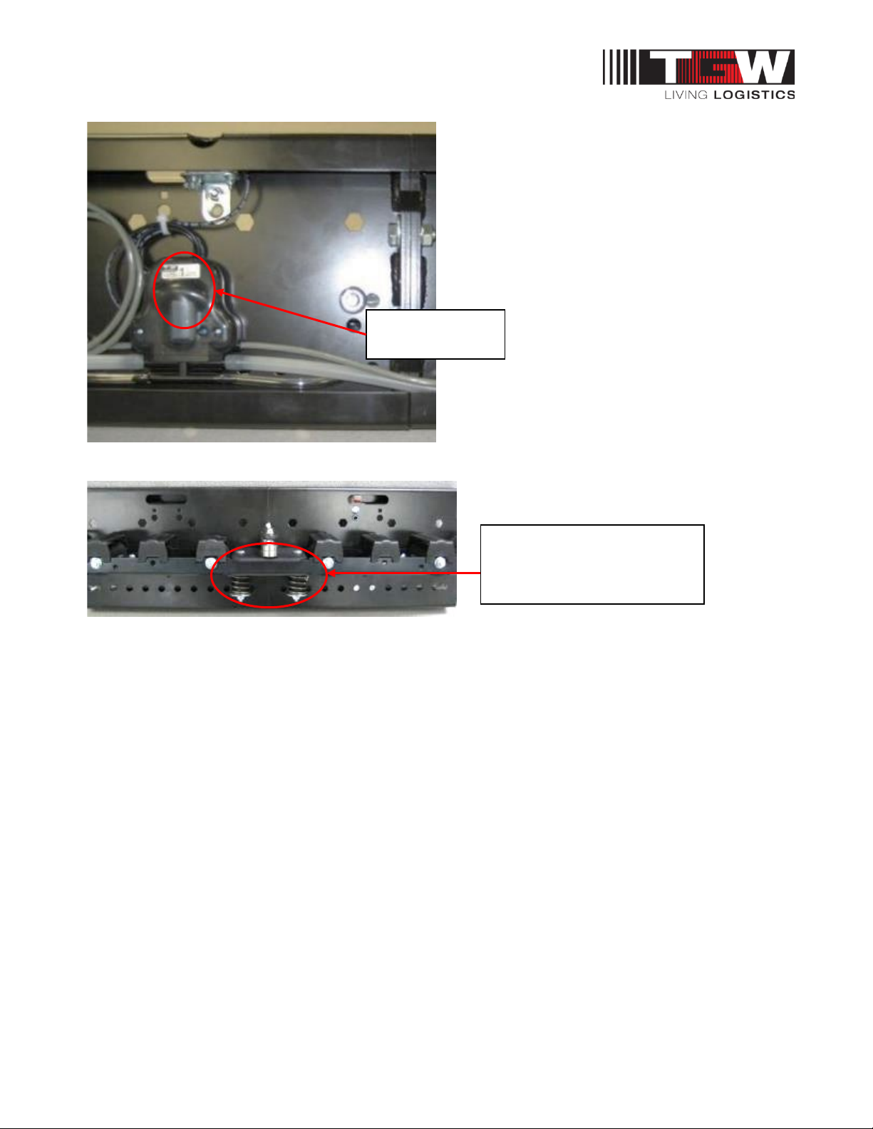
1.5: VALVE APPLICATIONS
NBC Air Transportation Conveyor
NBC Flat Belt Air Transportation is typically used in conjunction with a downstream NBC Flat Belt
Contact Accumulation conveyor.
Air Pilot Valve
NBC Air Transportation should be used when downstream accumulation is full. The air pilot valve
receives a signal from the last downstream accumulation zone and disengages the pressure pan
assemblies for the entire unit. Once the downstream zone clears, the pilot valve engages the pressure
pan assemblies and the transportation conveyor will continue to transport the products. The pilot valve
can be replaced with a solenoid valve and controlled through a PLC.
Item# Description
1120400 VALVE,PNEU-PILOT-A48
Pilot Valve
Tee into
downstream
pressure pan air
line
Air pilot
input
Input 40 psi pressure line (3/8” poly tube) from downstream
conveyor air header
3/8” poly tube from
upstream air
transportation
NBC™ Flat Belt - IOM
P/N: 1118140 Rev: 07/29/2020 Page 20 of 129
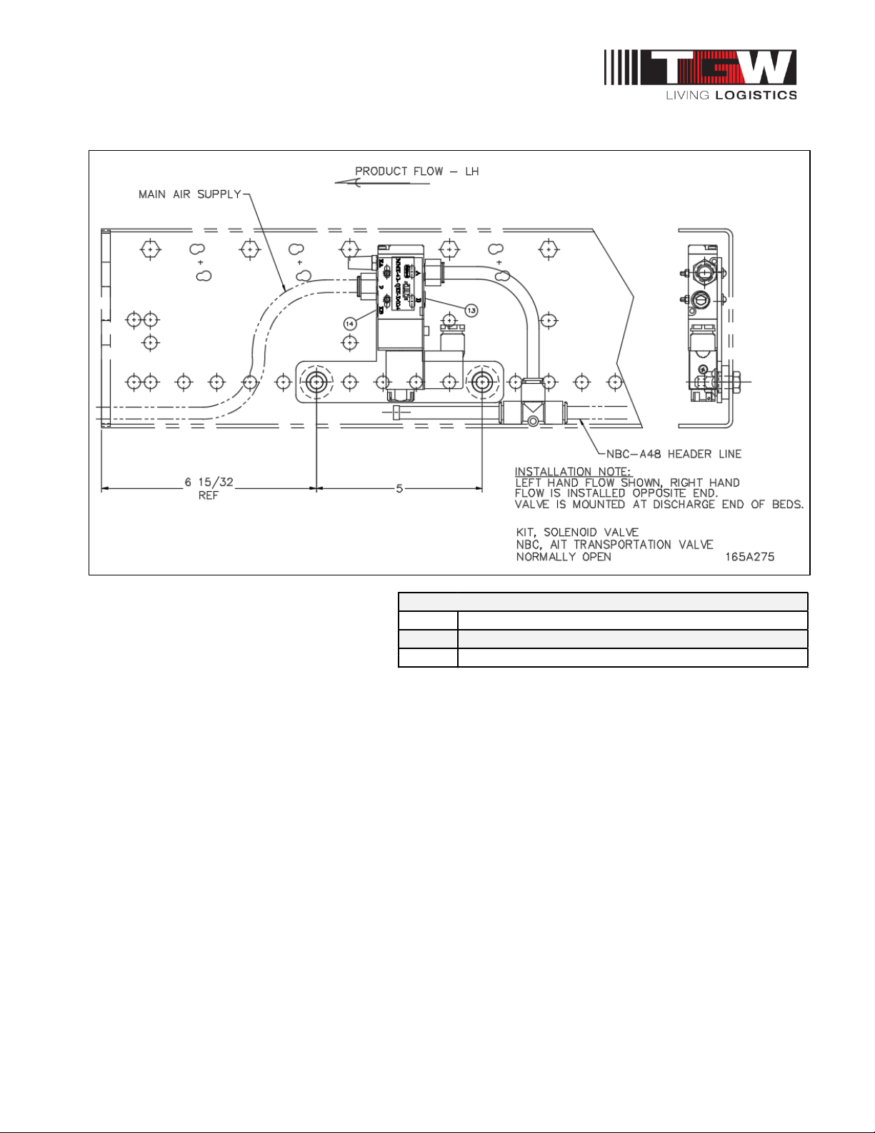
Solenoid valve
The Solenoid Valve Kit is controlled by an
external signal from the primary control
system supplied by the purchaser. The
Solenoid Valve Kit is typically mounted
near the last NBC contact accumulation
zone prior to the upstream NBC Air Transportation conveyor. The valve is normally open when no
signal is present, which causes the NBC Air Transportation conveyor to stop or accumulate. When the
last NBC Contact Accumulation zone clears, a control signal triggers the Solenoid Valve to activate
(close or stop the air flow) and the NBC Air Transportation conveyor will activate and convey the
product downstream. Review the detail above to determine correct Pilot or Solenoid Valve Kit on the
NBC Contact Accumulation conveyor flow.
Item# Description
1206186 KIT,CPART-SOL VALVE-24V-NBC AIR TRANS-VALVE OPEN
1206187 KIT,CPART-SOL VALVE-110V-NBC AIR TRANS-VALVE OPEN
Solenoid Valve
Other manuals for NBC
1
Table of contents
Other TGW Accessories manuals


