TGW NBS Series Instruction manual

1
Installation, Operation, Maintenance Manual
NBS®, NBS®30, NBS®90
Narrow Belt Sorter
90480005rev052411

NBS IOM
2
Contents
Purpose..................................................................................................................................... 3
Equipment Warranty.................................................................................................................. 4
Warnings & Safety Instructions.................................................................................................. 5
Definition of Terms .................................................................................................................... 8
Introduction to Narrow Belt Sortation....................................................................................... 10
NBS Application....................................................................................................................... 11
Receiving & Site Preparation................................................................................................... 13
General Procedures ................................................................................................................ 14
Supporting Arrangements........................................................................................................ 16
Belt Installation........................................................................................................................ 18
Air Supply Requirements......................................................................................................... 20
Air Line Connections ............................................................................................................... 23
Auxiliary Screw Belt Take-up................................................................................................... 25
Electrical.................................................................................................................................. 26
Commissioning of Equipment.................................................................................................. 28
NBS 90 Transfer Roller Adjustment Procedure....................................................................... 29
Preventive Maintenance.......................................................................................................... 30
NBS Maintenance Checklist.................................................................................................... 33
Maintenance Schedule............................................................................................................ 34
Repair Procedures................................................................................................................... 36
Parts Identification................................................................................................................... 39
Parts Identification - NBS 90 Transfer..................................................................................... 40
NBS 90-24 XM Transfer - Replacement Parts......................................................................... 41
NBS 90-30 XM Transfer - Replacement Parts......................................................................... 42
Parts Identification - NBS End Pulley ...................................................................................... 43
NBS End Pulley- Replacement Parts ...................................................................................... 44
Parts Identification - NBS Intermediate Bed ............................................................................ 45
NBS Intermediate Beds - Replacement Parts.......................................................................... 46
Parts Identification - NBS Drive 5′ Bed .................................................................................... 47
NBS Drive 5′ Bed - Replacement Parts................................................................................... 48
Parts Identification - NBS Drive 3′ Bed .................................................................................... 49
NBS Drive 3′ Bed - Replacement Parts................................................................................... 50
Parts Identification - NBS Take-up 5′ Bed ............................................................................... 51
NBS Take-up 5′ Bed - Replacement Parts .............................................................................. 52
Parts Identification - NBS Auxiliary Take-Up ........................................................................... 53
NBS Auxiliary Take-Up - Replacement Parts .......................................................................... 54
Parts Identification - NBS 30 3R Diverter Assembly................................................................ 55
NBS 30 3R Diverter - Replacement Parts................................................................................ 56
Parts Identification - NBS 30 WAVE™ Diverter Assembly....................................................... 57
NBS 30 WAVE™ Diverter Assembly - Replacement Parts...................................................... 58
Parts Identification - NBS 30 WAVE™ Aligner Assembly........................................................ 59
NBS 30 WAVE™ Aligner - Replacement Parts ....................................................................... 60
Parts Identification - NBS 30 12R Aligner Assembly ............................................................... 61
NBS 30 WAVE™ Aligner - Replacement Parts ....................................................................... 62
NBS Encoder Assembly .......................................................................................................... 63
MISSION.................................................................................................................................... 64
90480005rev010614

NBS IOM
3
Purpose
It is the intent of TGW Systems, through this manual, to provide information that acts as a guide in the installation,
operation and maintenance of TGW Systems NBS sorters including NBS 30, NBS 90 and NBS 90SP.
This manual describes basic installation practices, assembly arrangements, preventive maintenance and assists
in replacement parts identification.
This service manual is intended for use by personnel who are knowledgeable of installation and safe working
practices on conveyor systems.
Not all applications and conditions can be covered; therefore, this manual is to be used ONLY as a guide.
If additional copies of this manual are needed or if you have any question concerning the conveyor please contact
your Business Partner or TGW Systems Customer Support at 231-798-4547 or Fax 231-798-4146.
90480005rev010614

NBS IOM
4
Equipment Warranty
TGW warrants that the material and workmanship entering into its equipment is merchantable and will
be furnished in accordance with the specifications stated.
TGW agrees to furnish the purchaser without charge any part proved defective within 2 years from date
of shipment or before the equipment has forty-one hundred (4100) hours of running use, whichever
period is shorter, provided the purchaser gives TGW immediate notice in writing and examination
proves the claim that such materials or parts were defective when furnished. For drive components
specific to XenoROL® (i.e. Xeno belts, slave Xeno belts, drive spools, standard and speed-up, and
spacers), this warranty shall be extended to five years or ten thousand (10,000) hours of running use,
whichever period is shorter, provided the conveyors are applied, installed and maintained in
accordance with TGW published standards. Other than the above, there are no warranties which
extend beyond the description on the face hereof. Consequential damages of any sort are wholly
excluded.
The liability of TGW will be limited to the replacement cost of any defective part. All freight and
installation costs relative to any warranted part will be at the expense of the purchaser. Any liability of
TGW under the warranties specified above is conditioned upon the equipment being installed, handled,
operated, and maintained in accordance with the written instructions provided or approved in writing by
TGW.
The warranties specified above do not cover, and TGW makes no warranties which extend to, damage
to the equipment due to deterioration or wear occasioned by chemicals, abrasion, corrosion or erosion;
Purchaser's misapplication, abuse, alteration, operation or maintenance; abnormal conditions of
temperature or dirt; or operation of the equipment above rated capacities or in an otherwise improper
manner.
All equipment and components not manufactured by TGW carry only such warranty as given by
the manufacturer thereof, which warranty TGW will assign or otherwise make available to
Purchaser without recourse to TGW, provided that such warranty is assignable or may be made
available.
IMPORTANT
For service on motors, reduction units, electrical components, controls, air or hydraulic cylinders,
contact the local authorized sales and service representative of respective manufacturer. If none is
available in your locality, contact the TGW representative. TGW will not be responsible for units that
have been tampered with or disassembled by anyone other than the authorized representative of the
respective manufacturer.
THERE ARE NO WARRANTIES, EXPRESSED OR IMPLIED, INCLUDING, BUT NOT LIMITED TO,
WARRANTIES OF MERCHANTABILITY OR FITNESS FOR A PARTICULAR PURPOSE, EXTENDING
BEYOND THOSE SET FORTH IN THIS STATEMENT OF WARRANTY.
Rev 04/08/2009
90480005rev010614

NBS IOM
5
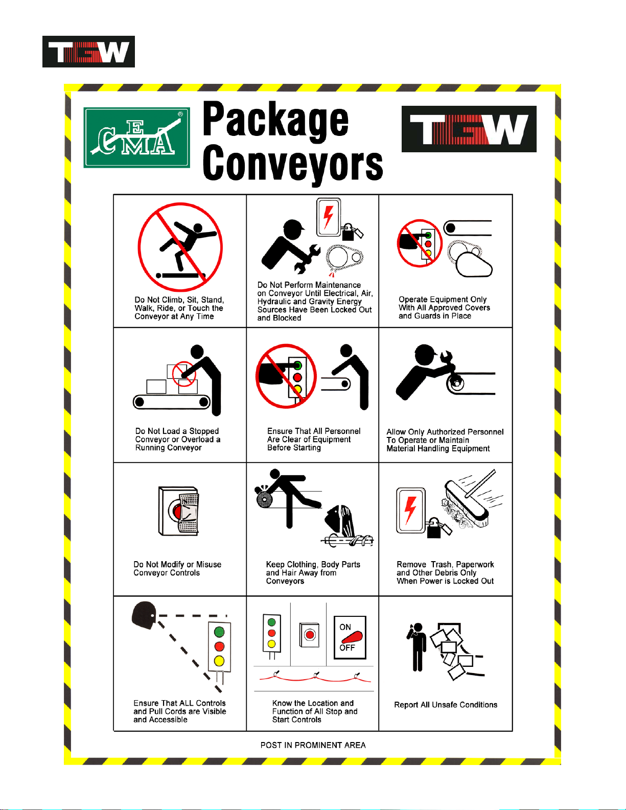
Warnings & Safety Instructions
Failure to follow the instructions, warnings, cautions (throughout this booklet) and warning labels (on the
conveyor) may result in injury to personnel or damage to the equipment.
Your TGW Systems NBS Narrow Belt Sorter is powered by a motor and can be stopped only by turning off
electrical power to the motor. As with all powered machinery, the drive and driven sprockets, chains, and
pneumatically actuated devices present a danger. We have installed or provided guards to prevent inadvertent
contact with these components along with warning labels to identify the hazards. After maintenance, REPLACE
guards immediately. Keep ALL warning labels clean and clear of any obstructions.
Be sure to read and heed all Warnings. Warnings and Cautions are included throughout this manual and are
defined as follows:
Warning ---- A notice which, if not followed, could
result in serious injury to personnel.
Caution ---- A notice which, if not followed, could
result in damage to equipment.
A thorough understanding and compliance with these Warnings and Cautions will greatly reduce the possibility of
personnel injury or equipment damage.
Never remove, deface or paint over any labels. Any damaged label will be replaced by TGW Systems Inc. at no
cost by contacting the Distributor Services Department.
WARNING
Do not perform maintenance on the conveyor until the start-up controls are locked out and cannot be turned on by
any person other than the one performing the maintenance. If more than one member of a crew is working on the
conveyor, EACH CREW MEMBER MUST HAVE A LOCK ON THE POWER LOCK OUT. The air pressure must
be turned off to the work area. All pneumatic devices must be de-energized to prevent accidental cycling of the
device.
Make sure personnel are clear of all conveyor equipment before restarting the system.
It is very important to instruct personnel in proper conveyor use including the location and function of all controls.
It is important to establish work procedures and access areas which do not require any part of a person to be
under the conveyor. It should be required that long hair is covered by caps or hair nets and the wearing of loose
clothing or jewelry when working at or near the conveyor be prohibited.
Maintain enough clearance on each side of the unit for safe adjustment and maintenance of components.
Provide crossovers at sufficient intervals to eliminate the temptation to climb over or under any conveyor. Prohibit
riding or walking on conveyor by anyone.
90480005rev010614

NBS IOM
6
WARNING
Before servicing or performing any work in the motor control panel, disconnect and lockout the main incoming
service. If only the panel disconnect is off, the incoming side will still be hot.
Warning examples on conveyor frames.
90480005rev010614
NBS IOM
7
90480005rev010614

NBS IOM
8
Definition of Terms
KEY WORD ABBREVATION DESCRIPTION
AIRBAG Inflatable lifting device used in NBS30
BEARING
“BRG”Low friction rotating or sliding device
BELT
“BLT”Flexible load carrying surface or O-ring
BETWEEN-FRAME
“BF”The distance between conveyor side frames
BRACKET
“BRKT”
Attachment between a main and another part
CHANNEL
“CH”Structural side member of conveyor equipment
CONNECTOR
“CONN”Adapts and holds two other parts together
CROSSMEMBER
“XM”Holds channels apart in NBS bed sections
DIVERTER NBS30 module
DRIVE
“DR”Power unit at the discharge end of NBS sorter
ELEVATION
“EL”Top-of belt height above base surface
ENCODER Electrical distaqnce counter used to track package locatio
ENDPULLEY
"E-PULL" 6” diameter roller at charge end of NBS sorter
EXTRUSION Aluminum base that holds UHMW belt strips
FEET PER MINUTE
“FPM”Speed sorter belts are traveling
FILTER / REGULATOR Combination air pressure regulator / air filter
FLOOR STAND
“FS”Name for conveyor bed support
FLOW CONTROL Needle valve used to control airflow
FOOTPAD Part used to distribute load from a jackscrew
GEARMOTOR
"GEARMTR" One piece gear-reducer motor assembly
GUARD RAIL
“GR”Angle or channel used to keep product on NBS
GUARD
“GRD”Any part used to protect area for safety reasons
IDLER Un-driven pulley used as a tensioning device
ITEM NUMBER
“IT #”TGW-ERMANCO part identification number
JOB NUMBER
"C010_ _ _ _ _" Original factory tracking order number
KEY Square locking device used on rotating shafts
KIT Group of several parts with a single item number
LACED
“LCD”The condition of a correctly installed lacing
LACING Type or method of joining belts together (splice)
LIFT FRAME The lifting structure of a NBS90 transfer
LIFT TABLE Assembly that guides the NBS30 wheels upward
LOCKNUT Self-locking fastener that resists vibration
LOCTITE A thread-locking adhesive that resists vibration
LOOSE PARTS
“LP”Individual parts that must be installed in the field
MULTI-BELT
“MBLT”Another name that describes NBS equipment
MODULE
“MOD”A self contained mechanical assembly
MOUNT
“MNT” Part used to hold another, similar to a bracket
MOUNTING
“MTG”Location and fasteners to attach a mount
MOTOR
“MTR”Rotational power source usually using electricity
MUFFLER Device used to reduce the noise of exhausted air
NATIONAL PIPE THREAD
“NPT”Standard identifier for USA tapered pipe sizes
PHOTOEYE
“PE”Optical sensing device used for product control
PLATE
“PL”Flat piece of metal usually bolted on for strength
90480005rev010614

NBS IOM
9
KEY WORD ABBREVATION DESCRIPTION
PROGRAMMABLE Self-contained programmable control unit that
LOGIC CONTROLLER
“PLC” Can control several input and output devices
O-RING Polyurethane cord belts of differing lengths
PULLEY
Roller described by diameter and body length
REDUCER
“RED” A C-face motor mount right-angle worm gearbox
REFLECTOR Target used to reflect a light back to a photo eye
REGULATOR
“REG” Air device that reduces pressure to usable level
RETAINER
Part used to mechanically lock a part in place
ROLLER Described by axle size and BF dimension
ROLLER CHAIN
“RC” Roller link chain used for power transmission
SCANNER A device that recognizes products by bar codes
SCHEMATIC Line drawing of a electrical or pneumatic circuit
SCREW A threaded fastener also called a bolt
SEAL Sealing device on a rotating shaft or cylinder rod
SMART DISTRIBUTED The name for a proprietary software / hardware
SYSTEM
“SDS” Network control system marketed by Honeywell Inc.
SHAFT Round steel rod described by diameter and length
SHEAVE A grooved disc that guides a V-belt or O-ring
SHIM Thin piece of metal, used to fill up a space
SKATEWHEEL
“SW” 2” diameter X 5/8” wide X ¼” axle hole roller
SMILEY
“J” (See standhead)
SOCKET
“SOC” Hex shaped hole in an Allen screw
SOLENOID
“SOL” An electrically operated multi-position air valve
SPACER Thick washer or tube that a fastener passes thru
SPLICE Area where similar materials are joined together
SPRING
“SPR” Coiled wire device used for un-powered return
SPROCKET
“SPKT” Wheel with shaped teeth that engage roller chain
SPUR Transition bed between a diverter and exit lane
STANDHEAD Pivoting bracket that attaches support to the bed
STARTER
Electrical relay that energizes the drive motor
TAG Number that identifies unit in system lay-out
TAKEUP Assembly used to remove slack from a belt / belts
TEE A part with three connections locations
TENSIONER A pneumatic, spring, or static take-up device
THREADED FULL LENGTH
“TFL” Adjusting bolt used in take-up/tracking applications
TRANSFER
“TRNS” NBS90 and NBS-SP module
ULTRA HIGH Industry standard term for the hard milky white
MOLECULAR WEIGHT
“UHMW” polyethylene used in wear strip applications
VALVE An air shut-off or switching device
VENT Small hole in gearbox to allow hot air expansion
WEARSTRIP Low-friction material used to reduce rubbing wear
WELDMENT
“WLDMT” Any part that requires welding in its manufacture
VFD Variable Frequency Drive for motor speed control
90480005rev010614

NBS IOM
10
Introduction to Narrow Belt Sortation
CONCEPT
The TGW Systems NBS Narrow Belt Sorter technology was developed to provide an economic alternative to
existing sortation devices, as well as providing sorting options that were not easily available. This technology is
similar to sorters that use wide flat load carrying belts and pop-up wheels to divert product but has eliminated
many of the high cost / maintenance features associated with these sorters. Limitations on availability of bi-
directional diverts, long divert lane center-line distances, as well as the high costs associated with the skilled labor
required to install these wide belt units have been addressed with this new technology.
FEATURES AND BENEFITS
Features and benefits common to the NBS 30, NBS 90, and NBS 90SP technology include:
•Product is continuously carried on multiple narrow belts for smooth bump-free conveying and excellent
tracking accuracy
•Narrow belts slide on low friction UHMW guides, resulting in reduced noise and virtually eliminating tracking
problems
•Multiple narrow belts are progressively guided through the sorter to minimize belt tracking issues
•Narrow belts run flat and straight through NBS modules without snubbing or back-wrapping resulting in
reduced horsepower requirements
•Simple user-friendly design allows ease of installation and maintenance
•Compact modular design of modules allows closer divert/transfer lane center distances
•Modularity and universal mounting of modules allows easy repositioning or reconfiguration in the field
•Gravity take-aways or spurs may be used in many applications to lower initial costs
•NBS technology costs less than conventional full width belt sorters in material as well as installation costs
NBS 30 AND NBS 30 WAVE™
•Simple 30 degree diverter design means less
maintenance and higher uptime
•Diverters use proven true vertical lift for reliability,
consistency and low cost
•High friction, diverter wheels with precision bearings
for positive quiet sorting
NBS 90 AND NBS 90SP
•Separate drive within the transfer module allows
a space saving single or bidirectional unit
•Coated rollers allow positive product acceleration
and transfer rate
•Pickup of product "on the fly" allows maximized
sort rate
90480005rev010614

NBS IOM
11
NBS Application
NBS Selection Guidelines
Use NBS When:
•Medium to high speed sortation is required
•Product may be same size and weight, or mixed
•Product weight: 1-75 lbs, 1500 lbs. total load
•Product size: 6" X 9" Min -- 28" X 28" Max
•Ambient temperature is +35° to 100°F (50° to 100°F for NBS 30 WAVE™ Aligner.)
APPLICATION NOTES
1. Matching conveyor rates before and after NBS
sortation are vital to proper application decisions.
2. The take-away lanes from NBS can be either skatewheel/gravity (used as a deceleration area), or powered
conveyor, run at a speed, which can receive products as fast as they are released from the NBS.
3. The maximum divert rate for a NBS 30 is 100 CPM (18" X 18" cases moving at 300 feet per minute); for NBS
30 WAVE it is 150 CPM at 425 FPM; for NBS 90 it is 60 CPM, and single-direction, bi-directional rate it is 50
CPM.
4. When feeding NBS sortation, use a split metering belt to singulate individual products with a minimum gap of
18". For NBS 30 WAVE, minimum gap is 6”.
5. For NBS30 justify all products along the divert lane side of the NBS sorter.
6. When the NBS over-all-length is over 100', an adjustable screw belt take-up unit must be installed to allow a
greater degree of belt take-up than is available from the main NBS drive take-up.
7. The maximum length of a NBS sortation conveyor, including an adjustable screw belt take-up unit, is 150'.
Max for NBS 30 WAVE is 100’, subject to 500 lbs. max belt pull limit.
8. The gearmotors used for NBS drives are all VFD (variable frequency drive) rated.
CAUTION
The use of a VFD (VARIABLE FREQUENCY DRIVE) is required for NBS drive motor control. Ignoring this point
may void the belt and motor manufacturer's warranty.
90480005rev010614

NBS IOM
12
GENERAL CONSIDERATIONS
ELEVATION (TOB)
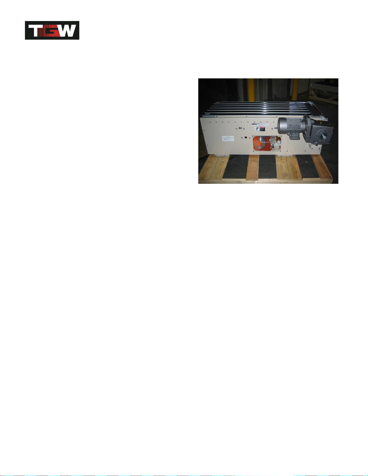
The minimum elevation at the discharge end of an NBS sortation line is 24". The drive unit is located there and
requires a space 24" high by 60" long by the frame width. Extra room along side the drive should be provided to
allow maintenance personnel access to either side of the drive unit.
DIVERT LOCATIONS
•The leading edge of the first divert module must be a minimum of 28" from the charge end of the sorter.
•The trailing edge of the last divert module must be a minimum of 70" from the discharge end.
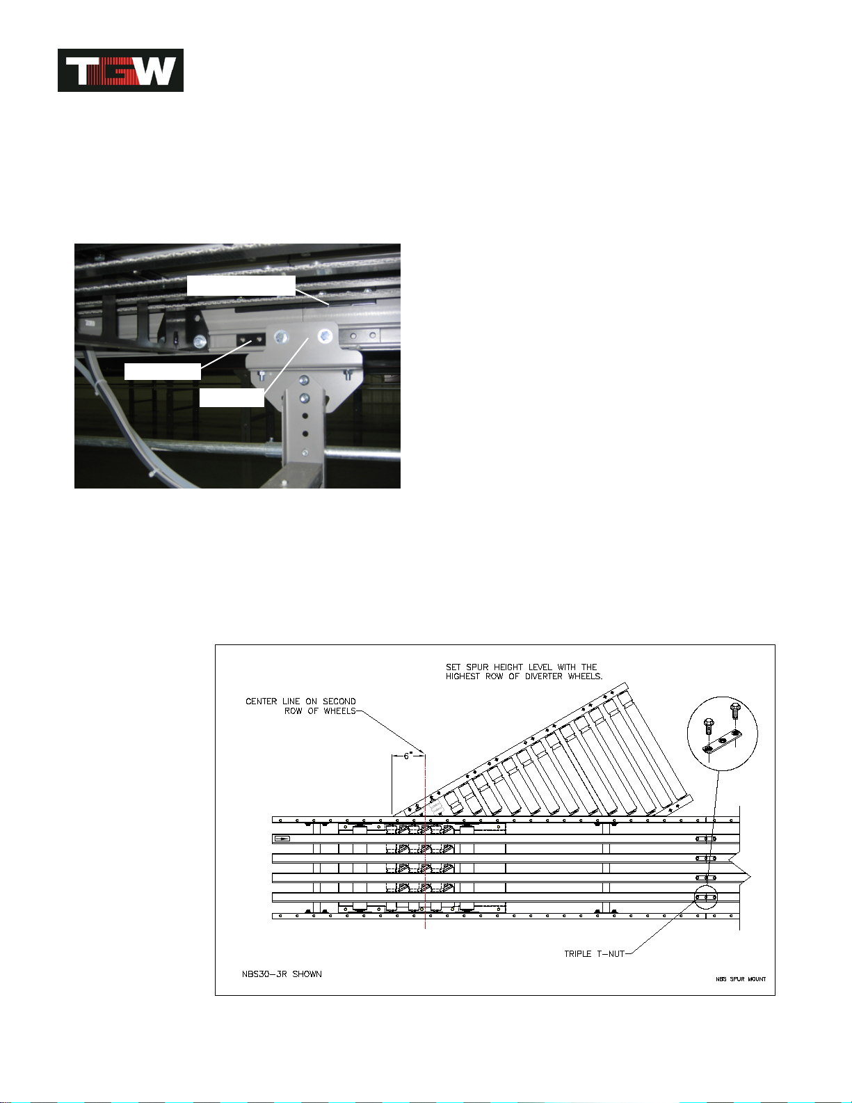
•The leading edge of a 30° spur mounts 6" ahead (up stream) of the center line of an NBS 30 divert.
•The leading edge of a 30° spur mounts 13½” ahead (up stream) of the FOURTH roller on an NBS 30 WAVE
divert.
•The location of a divert lane is centered or slightly downstream of the center line of the transfer rollers in a
NBS 90 and a NBS 90SP.
•One NBS 90 transfer with rollers up to 45" in length can transfer to two or four separate lanes.
•A single direction transfer to two lanes is called a "Dual Transfer"
•A bi-direction transfer to two lanes each side is called a "Quad Transfer"
AVAILABLE DRIVE SELECTIONS
1 HP @ 60 FPM
1.5 HP @ 90 FPM
2 HP @ 120, 150, 180 FPM
2 HP @ 200, 220, 250, 300 FPM
3 HP @ 180, 200, 220, 250, 300 FPM
5 HP @ 250, 300 FPM
7.5 HP @ 300, 325, 375, 425 FPM
SORTER NOMINAL WIDTHS (# OF BELTS)
18" with 4 Belts on 3-1/2" Centers
25" with 6 Belts on 3-1/2" Centers
32" with 8 Belts on 3-1/2" Centers
90480005rev010614
NBS IOM
13
Receiving & Site Preparation
GENERAL
TGW Systems NBS Narrow Belt Sorters are shipped in subassemblies. These subassemblies are packaged to
guard against damage in shipment, when handled properly.
Examination immediately following unloading will show if any damage was caused during shipment. If damage is
evident, claims for recovery of expenses to repair damage or replace components must be made against the
carrier immediately. While unloading, a check must be made against the Bill of Lading, or other packing lists
provided, to confirm full receipt of listed items.
CAUTION
TAKE CARE DURING THE REMOVAL OF EQUIPMENT FROM THE CARRIER. Remove small items and boxes
first. Pull and lift only on the skid, not on the frame, crossmember or any part of the equipment. Be sure the skid
is free of other materials which may be on top of or against the side of the skid to be removed.
PREPARATION OF SITE
After the conveyor is received, move it to the installation site
or designated dry storage area as soon as possible. Clean
up all packing material immediately before parts get lost in
it. Loose parts should remain in the shipping boxes until
needed.
Prior to starting assembly of the conveyor, carefully check
the installation path to be sure there are no obstructions that
will cause interference. Check for access along the path
needed to bring in bed sections and components closest to the point where they are needed. It is often necessary
to give the area along the system path a general cleanup to improve installation efficiency, access and accuracy.
PARTS INVENTORY & IDENTIFICATION
Each subassembly is shipped completely assembled except the bed joint splice plate/nuts which are shipped with
other loose parts. Identify and separate the sorter subassemblies by type or tag number, for inventory and ease
of locating during installation.
An identification label is attached to the inside of one side channel or on a crossmember, close to one end of each
conveyor bed. This label contains: job number, part number, order number, tag number (if specified), assembler's
initials and date of manufacture. On supports, the tag is located on the bottom side of the foot. On special
devices it is located on a convenient flat surface that is not offensive to the appearance of the equipment but is
still accessible for viewing. These numbers can be cross-referenced against the packing list. The illustrations in
this manual and the part number stickers will assist you with your inventory.
Identification Label
Loose parts are boxed and shipped separately. You should have
all conveyor sections and supports for a particular conveyor prior to
installation. It is cost-effective to identify and procure any missing
parts before they are needed for assembly. Small items like nuts
and bolts are weigh-counted and packaged by size and type.
CAUTION
Do not remove finishing nails from rail ends. They keep the
UHMW guides from sliding down to the discharge end.
90480005rev010614

NBS IOM
14
General Procedures
The following procedures are to be used as guidelines only. Specific installation methods will vary somewhat
depending on available equipment on site and each installer's preferences based on past experience.
WARNING
The Installation Supervisor must be experienced with conveyor and qualified in the mechanics of the equipment
and enforce safe working procedures for the protection of the crew, customer, and customer's property.
DIMENSIONAL REFERENCE POINTS
The path of each conveyor in the system is determined by establishing a reference point at each end. The center
line of the conveyor is established and a chalk line is snapped between these points.
Conveyors should be installed with the center line of the bed matching the center line of the conveyor path.
Locate and mark the center of the crossmembers at each end of the conveyor. Use a plumb line or other
acceptable means to ensure accuracy to the chalk line.
Always carry out a thorough check for any obstructions such as building columns, manholes, etc. It may be
necessary to reroute the conveyor to avoid the obstruction. In this case it would be advisable to begin installation
at this point, using the obstruction as a reference point (Datum), and install the sections in either direction as
required.
All conveyor sections must be checked for squareness prior to installation as "racking" or being knocked out of
square may have occurred during shipping and handling.
ELEVATIONS
All top-of-belt (TOB) heights should be installed in accordance with the elevations shown on the drawings. In
addition, all sortation devices must be level across both the frame width and length. Leveling of the frames is best
done using a rotating laser level along the length of the conveyor and a builder's level across the width.
After the first elevation is established at a critical point, the elevation of all other points shall be relative to this first
point. Normal practice is to dimension the layout and measure elevations from the floor at each point of support.
As the conveyor system proceeds onto another floor or into another building or room, a new elevation will be
measured from the floor at that point. This new elevation will then become the reference for subsequent
elevations.
When installing an overhead system, the first elevation is measured from the floor and becomes the reference
elevation point until a change in elevation is shown on the layout. Any new elevation is also measured from the
floor and becomes the new reference point. The process is repeated each time an elevation change occurs.
CAUTION
Consult the building architect or a structural engineer regarding ceiling loading or structural limitations of the
building if any conveyor is ceiling hung.
COMPONENT ORIENTATION
Using your conveyor system layout drawing and the numbers on the I.D. tags on each component, position and
orient the conveyor sections. You must know:
•The direction of product flow
•The elevation height
•The drive is positioned at the discharge end
•The end pulley is positioned at the charge end
90480005rev010614
NBS IOM
15
IMPORTANT! Do not make alterations to the equipment without consulting with user's representative and TGW
Systems. Unauthorized modifications to the equipment may impair its function, create a hazardous condition,
affect its useful life and/or void the warranty.
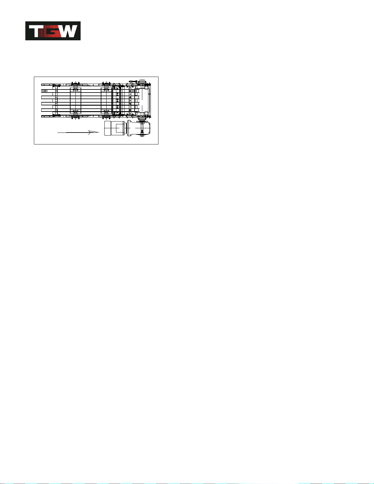
NBS66A034TV
FLOW
Discharge end bed with product flow direction.
90480005rev010614

NBS IOM
16
Supporting Arrangements
FLOOR SUPPORTS
Install bolts used to attach the standhead to the frame so the nut is on the bottom. Standhead bolts should be left
finger tight while the conveyor is being assembled and aligned.
Floor supports are ordered by nominal height range, which is the dimension from the floor to top of the support.
Conveyor elevations are shown on the layout by top-of-belt elevations. The difference between top of belt (TOB)
and top of support is 7-5/8". This dimension must be subtracted from the TOB height to set support height.
It is important that conveyor frames be installed level. Floor supports will accommodate normal irregularities in
the floor surface. Adjustment for elevation in floor supports is accomplished with metal-on-metal bolt clamping
force. To achieve the support's stated load rating, it is necessary to tighten the elevation adjustment bolts (3/8"
diameter) to 23 ft./lbs. of torque.
Supports should always be installed in the vertical position, and any variations due to conveyor pitch or floor slope
will be compensated for in the pivoting standhead of the support.
ANCHORING
Anchoring in concrete floors is accomplished by drilling into the floor and inserting the suitable anchor bolt. The
hole diameter and depth must be in accordance with the anchor bolt manufacturer's instructions.
Anchor intermediate floor supports with two anchor bolts, one through each support foot plate using at a minimum
3/8" diameter anchor bolts. For floor supports over 5' high or when supporting drives, use 1/2" diameter anchor
bolts.
Stagger anchors from front hole on one side of the support, to rear hole on opposite side. Anchor bolts for
equipment subject to impact loads should be a minimum of 1/2" in diameter.
WARNING
Place a bolt through the frame and support immediately with finger tight nut. This will prevent the frame from
falling off the support, if bumped, and causing injury.
90480005rev010614
NBS IOM
17
BED/SUPPORT CONNECTORS
NBS can only be supported at bed joins. Adjoining beds are connected using 3/8” thick by 10” nut plate, 3/16”
thick by 10” clamping plate and 3/8” hardware. These parts are shipped with other loose parts. Insert 10” nut plate
halfway into the formed channel end of each bed. Then mount standhead support with two 3/8-16 X 1” hex head
bolts with flat and lock washers. After that mount 10” clamp plate to channel ends with four 3/8-16 X 1” hex head
bolts with nut, flat and lock washers (see picture below). It can be seen that a crossmember could be moved into
the recessed area of the standhead support bracket if needed.
Maintaining the rigidity and flatness of the conveying surface is the end result of proper support installation.
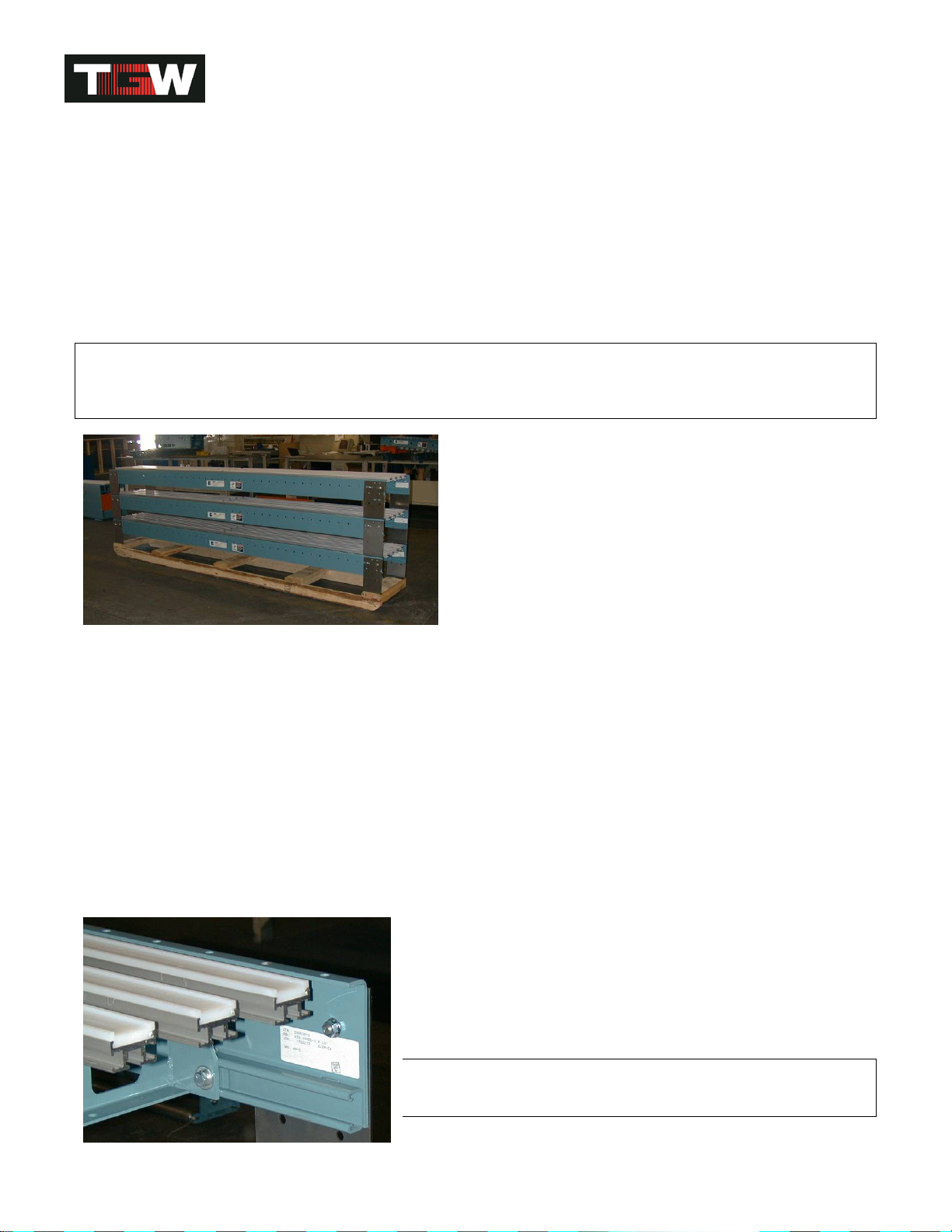
ALUMINUM EXTRUSION T-NUT CONNECTORS
The aluminum extrusions that hold the UHMW belt guides are installed at the factory with tee bolts up through
their mounting crossmembers. The placement of these extrusions is gauged precisely (2-5/16" center-to center)
so that the triple T-nut connectors between the extrusions line up at installation. The triple T-nut connectors are
mounted, at the factory, flush with the ends of the aluminum extrusions on the discharge side of all NBS bed
assemblies. These triple nut connectors should be extended half-way out of the extrusions before "plugging in"
the next bed
downstream during
installation. After all
bed components are
installed, leveled
and straightened the
5/16-18 hex head
bolts used in the
triple T-nut
connectors should
all be loosened, to
straighten the
aluminum extrusion
joints and re-
tightened.
10” nut plate
10” clamping plate
standhead
90480005rev010614
NBS IOM
18
Belt Installation
PRE-INSTALLATION
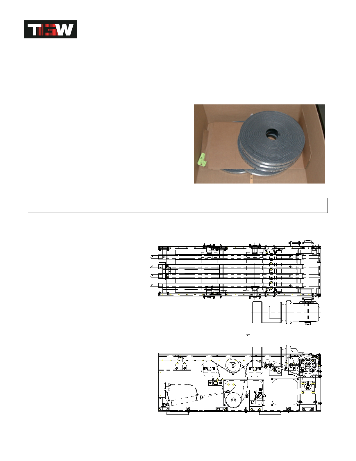
Belts, as shipped from TGW Systems, are cut to length with
lacing installed. Rolls of belting should be stored on edge
on a pallet (see belt below). Never leave a belt where it
may absorb moisture. Remove any tight shipping banding
immediately upon arrival. Lacing pins are taped inside the
lacing on each belt.
The NBS conveyor should be completely installed and
aligned before belt installation.
Remove the plexiglass side covers from the sides of the
drive frame, exposing the take-up pulleys. Switch the take-
up air switch to the un-tensioned position, raising the take-
up pulleys to the minimum take-up position. Then remove or
slide covers between the aluminum belt track extrusions so
that the belt guide wheels are exposed. Do the same for
each NBS 30 diverter and the charge end pulley.
Remove the o-ring from the o-ring driven gap roller.
BELT THREADING
Because NBS uses multiple narrow belts of long length, it will be most efficient to have two people working
together during the threading process.
The belting must be uncoiled and laid out flat on the sorter, with the smooth black carrying surface up. The belts
must not be allowed to twist along their length as they are installed. Start at the charge end (farthest from the
drive) and feed all of the belts through together at the same time. Start the belts down between the gap roller and
the end pulley. Guide the belts under the 5" diameter end pulley and up and over the 4" diameter snub pulley,
before passing through the belt guide wheels.
All belts must pass over any return rollers positioned to minimize belt sag and through holes in crossmembers.
NBS 30 diverts use the moving narrow belts to drive the pop-up divert wheels. The narrow belts must pass over
the first roller in the divert, under the next three rollers (six rollers on NBS 30 WAVE™), over the last roller and
then between the belt guide wheels as they exit the diverter.
NBS 90 divert rollers fit up between the narrow belts.
Thread the belts through the drive unit using the diagram on the following page as a guide. The black PVC
surface of the belt should be up and the rough surface rides in the UHMW tracks.
Mesh the loops of the lacing on one end of the belt with the loops on the other, so the sides of the belt are even,
and install the lacing pin.
Because the different width sorters have different numbers of belts, the air pressure to properly tension the belts
is different for each width.
90480005rev010614
NBS IOM
19
BELT TRACKING
With the belts tensioned, "bump" the motor to be sure rotation is correct, the belts are running smoothly and
maintaining their position. Most NBS conveyors do not require belt tracking. However, each conveyor should be
checked at the charge and discharge ends to be sure the belts are floating in a neutral position not crowding the
sides of the UHMW guide tracks. If the belts are out of their grooves or riding hard to one side adjustment can be
made on the driven pulley jackscrew, at the discharge end, or the snubber roller in the end pulley assembly at the
charge end, to realign them.
Reinstall the bottom pan on the end pulley assembly and
access covers on the drive bed, NBS 30 diverter and charge
end pulley.
BELT SPECIFICATIONS AND LACING
Belting:
•PVC 200 belt
•Width: 1-1/4" +/-1/16"
•Thickness: .203" +/- .015
•Lace: Clipper U3RTS w/#3 point
•Lacing Pin: DSS093 x 1-1/8 +/-1/32" long .093 “WHITE
DURAPIN COATING” .048 304 stainless steel core
CAUTION
Only use the specified lacing and pin. Any substitution will result in premature belt failure.
For field repair chamfer belt corners, no more than 1/4”. Belts to have six (6) hooks on one side and seven (7)
hooks on the other for maximum strength.
BELT REPLACEMENT
Replacement belts may be ordered by the
original "P" part number marked on the
belt or belt length can be determined by
the following information.
1. The 3’ drive bed requires 6’-5” (77”)
2. The 5' drive bed requires 10'-8" (128")
3. The 18" end pulley bed 3'-0" (36")
4. NBS 30 diverters require 3/8" each
5. NBS 30 WAVE diverters require 3/8"
each
6. NBS 90 transfers require 0" each
7. Auxiliary take-up requires 1'4" (16")
8. The 5’ air take-up bed requires 10’-3”
(123”)
9. All other beds require 2 times their
length.
10. The 6’ drive bed requires 16’-0” (192”)
NOMINAL WIDTHS (# OF BELTS)
18" with 4 Belts on 3-1/2" Centers
25" with 6 Belts on 3-1/2" Centers
32" with 8 Belts on 3-1/2" Centers
FLOW
NBS66A034A
5' DRIVE BED (18NBS SHOWN)
90480005rev010614

NBS IOM
20
Air Supply Requirements
OVERHEAD FEEDER LINE
LOCKOUT / SHUTOFF
COMPRESSOR
TANK
WATER
LEG FILTER/REGULATOR
1/2" TUBING
TO CONVEYOR
SHUTOFF
WATER
LEG
LOCKOUT / SHUTOFF
TO CONVEYOR
DROP
LINE SHUTOFF
1/2" TUBING
NBSAIR
FILTER/REGULATOR
DROP LINE
(3/4" OR LARGER) DROP LINE (3/4" OR LARGER)
Suggested requirements for NBS sorter and diverts
OVERHEAD FEEDER LINE
LOCKOUT / SHUTOFF
COMPRESSOR/
TANK WATER
LEG
FILTER / REGULATOR
SHUTOFF
WATER
LEG
LOCKOUT / SHUTOFF
SHUTOFF
NBSAIR-WAVE
FOR A PRE-ALIGNER
FILTER / REGULATOR
3/4" PIPE HEADER WAVE
DROP LINE
(1" OR LARGER)
FOR EACH
PRE-ALIGNER
DROP LINE (1" OR LARGER) PER
FIVE DIVERTS OR LESS
3/4" PIPE HEADER
3/8" TUBING (5' ORLESS)
PER WAVE DIVERT
1/2" TUBING (5' OR LESS)
Suggested requirements for NBS WAVE™ sorter, aligner and diverts
GENERAL
Every conveyor system is unique, with its own specific requirements. Therefore, the following is a general guide.
MAIN FEEDER: Air velocity through the main feeder piping can be kept smooth with lower losses using large
diameter pipe with minimum bends and restrictions. Standard weight black pipe or copper is suitable for plumbing
the compressed air overhead to all points of use.
AIR DROPS: TGW Systems recommends using 3/4" pipe on air drops for high flow and low pressure loss on all
sorters except WAVE sorters NBS 30-3R, 5R, 90. The drop is terminated with a drain at the bottom. A tee
located prior to the drain branches off to the conveyor. This branch line must contain a lockout/shutoff. A shutoff
must also be located in the drop before the branch tee. OSHA Rule 29, CFR1910.147 requires energy sources
(air drops) be turned off and capable of being locked or labeled with a warning tag. NBS 30 WAVE™ sorters
should be fed with ¾” tube along length of conveyor.
AIR DROPS AND HEADERS FOR WAVE DIVERT
The NBS WAVE divert and aligner require higher air capacity than the NBS 30 or NBS 90 divert. As six rows of
divert wheels must fire within a fraction of a second, the “burst” air capacity must be adequate or sluggish and
inconsistent divert action will result. We recommend the following minimum air plumbing of the WAVE divert and
aligner:
90480005rev010614
This manual suits for next models
4
Table of contents
Other TGW Accessories manuals


Popular Accessories manuals by other brands

Briggs & Stratton
Briggs & Stratton Wireless Monitor Kit Installation and operation manual

Brinsea
Brinsea Ovation 28 EX operating manual

Palram
Palram Sierra 2.3x2.3 Assembly instructions

Microsonic
Microsonic mic+ Series operating manual

GF
GF Signet 3-2100-2H operating instructions

Charzon
Charzon VALENTINE owner's manual


ZIEHL
ZIEHL S1 adjustable operating manual

Precision Sound Lab
Precision Sound Lab RCA socket Mk7 Fitting instructions

Friedrich
Friedrich WALLMASTER SUBBASE WE installation instructions

MaiJia Intelligent Technology
MaiJia Intelligent Technology MJ-VU01 manual

Bowflex
Bowflex SelectTech BD552 owner's manual

YachtSafe
YachtSafe W020 manual