TGW XenoROL XR40 Instruction manual

INSTALLATION, OPERATION,
MAINTENANCE MANUAL
XenoROL®
XR40 and XR48
90480006rev101210

1
XR40 and XR48 IO0
PURPOSE ............................................................................................................................................................................. 3
EQUIPMENT WARRANTY ................................................................................................................................................... 4
XENOROL CONCEPT .......................................................................................................................................................... 5
WARNINGS & SAFETY INSTRUCTIONS ........................................................................................................................... 5
INTRODUCTION TO XENOROL .......................................................................................................................................... 5
PRECAUTIONS .................................................................................................................................................................... 5
DEFINITION OF TERMS ...................................................................................................................................................... 6
CAPACITY OF ROLLERS/FRAME ...................................................................................................................................... 7
MINIMUM PRESSURE ACCUMULATION ........................................................................................................................... 7
REDUCTION OF LINE PRESSURE ..................................................................................................................................... 7
GENERAL ............................................................................................................................................................................. 8
PREPARATION OF SITE ...................................................................................................................................................... 8
PARTS INVENTORY & IDENTIFICATION ........................................................................................................................... 8
RECEIVING & SITE PREPARATION ................................................................................................................................... 8
TYPICAL XENOROL® LOOSE PARTS ............................................................................................................................... 9
DIMENSIONAL REFERENCE POINTS ............................................................................................................................. 10
ELEVATIONS ...................................................................................................................................................................... 10
GENERAL PROCEDURES ................................................................................................................................................ 10
COMPONENT ORIENTATION ............................................................................................................................................ 10
TYPICAL LAYOUT/LEGEND .............................................................................................................................................. 11
LAYOUT DIMENSIONS ...................................................................................................................................................... 12
LINE-SHAFT TERMINATIONS ........................................................................................................................................... 13
FLOOR SUPPORTS ........................................................................................................................................................... 14
SUPPORTING ARRANGEMENTS..................................................................................................................................... 14
CONNECTORS ................................................................................................................................................................... 15
KNEE BRACES .................................................................................................................................................................. 15
CEILING HANGERS ........................................................................................................................................................... 16
SWAY BRACING (CEILING HANGER).............................................................................................................................. 17
DIAGONAL SWAY BRACE (FLOOR SUPPORT) .............................................................................................................. 17
MULTI-LEVEL XENOROL® SUPPORT ............................................................................................................................. 18
GENERAL ........................................................................................................................................................................... 19
BASICS OF XENOROL® INSTALLATION ....................................................................................................................... 19
DRIVES ............................................................................................................................................................................... 22
SUBASSEMBLY INSTALLATION ...................................................................................................................................... 22
CURVES ............................................................................................................................................................................. 22
JUMP CHAINS/BELTS ....................................................................................................................................................... 23
MERGE ASSEMBLY .......................................................................................................................................................... 24
SPURS ................................................................................................................................................................................ 24
TRAFFIC CONTROLLER ................................................................................................................................................... 25
XENOSWITCH ASSEMBLY ............................................................................................................................................... 25
WHEEL DIVERTER ASSEMBLY ....................................................................................................................................... 26
URETHANE BELT TRANSFER (UBT) ............................................................................................................................... 27
UBT XENOBRAKE ............................................................................................................................................................. 28
PIVOTING ROLLER STOP ................................................................................................................................................ 28
RIGHT ANGLE CONNECTION / URETHANE BELT TRANSFER MODULE (RAC/UBT MODULE) ................................ 29
XENOBRAKES ................................................................................................................................................................... 30
POWERED GATE ASSEMBLY .......................................................................................................................................... 31
ROLLERS ........................................................................................................................................................................... 32
LINE-SHAFT GUARDS ...................................................................................................................................................... 33
GUARD RAILS ................................................................................................................................................................... 34
GENERAL ........................................................................................................................................................................... 35
AIR SUPPLY REQUIREMENTS ......................................................................................................................................... 35
AIR CONSUMPTION .......................................................................................................................................................... 35
PRESSURE SWITCH ......................................................................................................................................................... 35
GENERAL ........................................................................................................................................................................... 36
ELECTRICAL ..................................................................................................................................................................... 36
SAFETY GUIDELINES ....................................................................................................................................................... 36
GENERAL ........................................................................................................................................................................... 38
COMMON ADJUSTMENTS ............................................................................................................................................... 38
90480006rev101210

2
COMMISSIONING OF EQUIPMENT .................................................................................................................................. 38
DRIVE BELT BREAK-IN .................................................................................................................................................... 38
GENERAL ........................................................................................................................................................................... 39
MOTOR AND GEARCASE ................................................................................................................................................. 39
PREVENTIVE MAINTENANCE .......................................................................................................................................... 39
CHAINS AND SPROCKETS .............................................................................................................................................. 39
TIMING BELT & PULLEYS................................................................................................................................................. 40
TIMING BELT TAKEUP & TENSION.................................................................................................................................. 40
ROLLERS ........................................................................................................................................................................... 41
DRIVE BELTS & LINE-SHAFT BEARINGS....................................................................................................................... 42
SUPPORTS/FRAMEWORK................................................................................................................................................ 42
UNIVERSAL JOINTS.......................................................................................................................................................... 42
COUPLER SPROCKETS/CHAINS .................................................................................................................................... 43
GUIDE POSTS .................................................................................................................................................................... 43
AIR SYSTEMS .................................................................................................................................................................... 43
MAINTENANCE SCHEDULE ............................................................................................................................................. 44
LUBRICATION GUIDE ....................................................................................................................................................... 45
TROUBLESHOOTING GUIDE ........................................................................................................................................... 46
TROUBLESHOOTING GUIDE-MECHANICAL .................................................................................................................. 47
TROUBLESHOOTING GUIDE-MECHANICAL .................................................................................................................. 48
TROUBLESHOOTING GUIDE-MECHANICAL .................................................................................................................. 49
TROUBLESHOOTING GUIDE-MECHANICAL .................................................................................................................. 50
TROUBLESHOOTING GUIDE-MOTOR/REDUCER .......................................................................................................... 51
TROUBLESHOOTING GUIDE-MOTOR/REDUCER .......................................................................................................... 52
TROUBLESHOOTING GUIDE-ELECTRICAL ................................................................................................................... 53
REPAIR PROCEDURES .................................................................................................................................................... 54
COUPLER CHAINS ............................................................................................................................................................ 54
CHAIN & SPROCKETS ...................................................................................................................................................... 54
UNIVERSAL JOINTS ......................................................................................................................................................... 55
LINE-SHAFT BEARINGS (STANDARD) ............................................................................................................................ 55
LINE-SHAFT ....................................................................................................................................................................... 56
REDUCERS/GEARMOTORS ............................................................................................................................................. 56
RIGHT ANGLE CONNECTION .......................................................................................................................................... 56
DRIVE BELTS ..................................................................................................................................................................... 57
XENOBRAKES ................................................................................................................................................................... 58
SOLENOID VALVES .......................................................................................................................................................... 58
MOTOR CONTROLS .......................................................................................................................................................... 59
SENSING SWITCHES ........................................................................................................................................................ 59
PARTS IDENTIFICATION .................................................................................................................................................. 60
INTERMEDIATE BEDS ...................................................................................................................................................... 60
CURVES ............................................................................................................................................................................. 60
DRIVE PACKAGE AND BED ............................................................................................................................................. 62
LOW PROFILE DRIVE PACKAGE AND BED ................................................................................................................... 62
URETHANE BELT TRANSFERS ....................................................................................................................................... 63
URETHANE BELT TRANSFER OPTIONS ........................................................................................................................ 63
JUMP CHAIN ASSEMBLY ................................................................................................................................................. 64
RIGHT ANGLE CONNECTION / URETHANE BELT TRANSFER MODULE .................................................................... 64
WHEEL DIVERTER ASSEMBLY ....................................................................................................................................... 65
MERGE ASSEMBLY .......................................................................................................................................................... 65
GATE .................................................................................................................................................................................. 66
XENOSWITCH ASSEMBLY ............................................................................................................................................... 66
XENOBRAKE ..................................................................................................................................................................... 67
LOCATING STOP AND PIVOTING ROLLER STOP .......................................................................................................... 67
ROLLER DATA ................................................................................................................................................................... 68
PARTS IDENTIFICATION LIST .......................................................................................................................................... 69
PARTS IDENTIFICATION LIST .......................................................................................................................................... 70
ADDITIONAL REPLACEMENT PARTS............................................................................................................................. 71
XR40/48 DRIVE BELT DATA .............................................................................................................................................. 72
DRIVE PARTS IDENTIFICATION ...................................................................................................................................... 73
LOW PROFILE DRIVE DATA ............................................................................................................................................. 74
90480006rev101210

3
90480006rev101210
It is the intent of TGW Systems Inc., through this manual, to provide
information that acts as a guide in the installation, operation and mainte-
nance of TGW Systems XenoROL ® conveyors.
This manual describes basic installation practices, assembly arrange-
ments, preventive maintenance, repair procedures, troubleshooting, ser-
vice intervals and assists in replacement parts identification.
If additional copies of this manual are needed or if you have any question
concerning the conveyor, please contact Customer Service at
231/798-4547 or Fax 231/798-4146.
PURPOSE

90480006rev101210 4
EQUIPMENT WARRANTY
TGW Systems warrants that the material and workmanship entering into its equipment is merchantable
and will be furnished in accordance with the specifications stated.
TGW Systems agrees to furnish the purchaser without charge any part proved defective within 2 years
from date of shipment or before the equipment has forty-one hundred (4100) hours of running use,
whichever period is shorter, provided the purchaser gives TGW Systems immediate notice in writing
and examination proves the claim that such materials or parts were defective when furnished. For drive
components specific to XenoROL® (i.e. Xeno belts, slave Xeno belts, drive spools, standard and
speed-up, and spacers), this warranty shall be extended to five years or ten thousand (10,000) hours of
running use, whichever period is shorter, provided the conveyors are applied, installed and maintained
in accordance with TGW Systems published standards. Other than the above, there are no warranties
which extend beyond the description on the face hereof. Consequential damages of any sort are
wholly excluded.
The liability of TGW Systems will be limited to the replacement cost of any defective part. All freight
and installation costs relative to any warranted part will be at the expense of the purchaser. Any liability
of TGW Systems under the warranties specified above is conditioned upon the equipment being
installed, handled, operated, and maintained in accordance with the written instructions provided or
approved in writing by TGW Systems.
The warranties specified above do not cover, and TGW Systems makes no warranties which extend to,
damage to the equipment due to deterioration or wear occasioned by chemicals, abrasion, corrosion or
erosion; Purchaser's misapplication, abuse, alteration, operation or maintenance; abnormal conditions
of temperature or dirt; or operation of the equipment above rated capacities or in an otherwise improper
manner.
All equipment and components not manufactured by TGW Systems carry only such warranty as given
by the manufacturer thereof, which warranty TGW Systems will assign or otherwise make available to
Purchaser without recourse to TGW Systems, provided that such warranty is assignable or may be
made available.
IMPORTANT
For service on motors, reduction units, electrical components, controls, air or hydraulic cylinders,
contact the local authorized sales and service representative of respective manufacturer. If none is
available in your locality, contact the TGW Systems representative. TGW Systems will not be
responsible for units that have been tampered with or disassembled by anyone other than the
authorized representative of the respective manufacturer.
THERE ARE NO WARRANTIES, EXPRESSED OR IMPLIED, INCLUDING, BUT NOT LIMITED TO,
WARRANTIES OF MERCHANTABILITY OR FITNESS FOR A PARTICULAR PURPOSE, EXTENDING
BEYOND THOSE SET FORTH IN THIS STATEMENT OF WARRANTY.
Rev 04/08/2009

5
90480006rev101210
WARNINGS & SAFETY INSTRUCTIONS
Failure to follow the instructions, warnings, cau-
tions (throughout this booklet) and warning labels
(on the conveyor) may result in injury to personnel
or damage to the equipment.
Never remove, deface or paint over WARNING or
CAUTION labels. Any damaged label will be replaced
by Ermanco Inc. at no cost by contacting the Distributor
Services Department.
It is very important to instruct personnel in proper con-
veyor use including the location and function of all con-
trols. It is important to establish work procedures and
access areas which do not require any part of a person
to be under the conveyor. It should be required that
long hair be covered by caps or hair nets and the wear-
ing of loose clothing or jewelry when working at or near
the conveyor be prohibited.
Maintain enough clearance on each side of the unit for
safe adjustment and maintenance of components.
Provide crossovers or gates at sufficient intervals to
eliminate the temptation to climb over or under any con-
veyor. Prohibit riding or walking on conveyor by any-
one.
REMOVE ALL UNUSED COUPLER SPROCKETS.
AT OPEN ENDS (TERMINATION) OF XenoROL
CONVEYORS, ADD THE SET COLLAR PROVIDED
TO THE END OF THE LINE-SHAFT AND INSTALL
THE LINE-SHAFT END COVER. THE SET COLLAR
AND ORANGE END COVER ARE FOUND IN THE
LOOSE PARTS BOX.
INTRODUCTION TO XenoROL
XENOROL CONCEPT
XenoROL rollers are driven by pretensioned polyure-
thane belts which pull the drive spools against the line-
shaft. Each spool delivers a fixed amount of torque
from the line-shaft to the rollers. This torque is based
on the drive belt tension and coefficient of friction be-
tween the spool and line-shaft. If the torque require-
ment to drive the load on the rollers exceeds the fixed
torque of the spool, the spool slips on the line-shaft like
a clutch.
PRECAUTIONS
TEMP. RANGE (AMBIENT): 35°F to 100°F. For tem-
perature applications outside this range, consult the
Distributor Services Department.
ULTRAVIOLET RAYS: Avoid exposure of polyure-
thane belts to sunlight.
OILY OR WET CONDITIONS: Will impair frictional
drive characteristics between spool and line-shaft.
CORROSIVE OR ABRASIVE SUBSTANCES: Will
adversely affect various components, voiding the war-
ranty.
XenoROL conveyor allows unequaled versatility with
high speed, complete reversibility and minimum pres-
sure accumulation. A major benefit of XenoROL line-
shaft driven conveyor is the ability to power straight
sections and curves plus auxiliary devices from a single
drive. Auxiliary equipment includes: transfers, spurs,
adjoining parallel sections, merges, switches, sortation
devices, powered guard rails, etc.
Your XenoROL® line-shaft driven live roller conveyor is
powered by a motor and can be stopped only by turning
off electrical power to the motor. As with all powered
machinery, the drive and driven sprockets, chains, line-
shafts, universal joints and pneumatically actuated de-
vices present a danger. We have installed or provided
guards to prevent inadvertent contact with these com-
ponents along with warning labels to identify the haz-
ards. After maintenance, REPLACE guards imme-
diately. Keep ALL warning labels clean and clear
of any obstructions.
Warnings and Cautions are included throughout this
manual and are defined as follows:
WARNING - A notice which, if not followed, could
result in a serious injury to
personnel.
CAUTION - A notice which, if not followed, could
result in damage to equipment.

6
90480006rev101210
DEFINITION OF TERMS
Accessory - A device which receives power from and
contributes to the horsepower requirement of the line-
shaft.
Accumulation (Minimum Pressure) - Act of queuing,
holding, or backing up of product on a conveyor.
Carrying Roller - The conveyor roller upon which the ob-
ject being transported is supported. It has a circumfer-
ential groove near one end to allow the drive belt to ride
below the carrying surface.
Coefficient of Friction - A numerical expression of the
ratio between the force of contact between two sur-
faces and the resistant force tending to oppose the
motion of one with respect to the other.
Conveyor Width - The dimension outside to outside of
frame rails. For the inside dimension, the abbreviation
used is "BF" (between frames).
Coupler - A mechanical device which connects seg-
ments of the line-shaft.
Coupler Chain - A double wide chain, plastic or metal,
which performs the function of connecting one sprocket
to an adjacent sprocket.
Coupler Sprocket - A sprocket located at the extreme
end of a line-shaft, positioned to allow connection to a
second sprocket on another line-shaft by using a cou-
pler chain.
Crossmember - Structural member which is assembled
between two side channels of a conveyor bed.
Drive - An assembly of mechanical, electrical, and
structural components to provide power to line-shaft.
Drive Belt - An endless round belt manufactured from
elastic material, typically urethane, connecting spools to
carrying rollers for transmitting rotation of line-shaft.
Drive Sprocket - The sprocket which propels the chain
or synchronous belt.
Driven Sprocket - The sprocket which is propelled by
the chain or synchronous belt.
Frame - The structure which supports the components
of a conveyor bed consisting of formed channel rails
bolted together with square tubing crossmembers.
Guard Rail - Members paralleling the path of a conveyor
and limiting the unit loads to movement in a defined
path.
Jump Chain - A drive chain or belt which transmits
power from one line-shaft to an adjacent parallel line-
shaft. A crossover between adjacent line-shafts within
a common conveyor frame is called an internal jump
chain. A crossover between a line-shaft in one con-
veyor frame and a line-shaft in an adjacent parallel con-
veyor frame is called an external jump chain.
Line-shaft - Shaft which runs longitudinally within line-
shaft conveyor to provide power transmission to carry-
ing rollers and accessory equipment.
Line-shaft Bearing - The pillow block style bearings in
which the line-shaft rotates.
Line-shaft Curve - A curved conveyor section equipped
with a line-shaft segmented with universals to change
the direction of product travel horizontally. The curve
radius is measured to the inside face of the inside frame
rail.
Line-shaft Guard - Provided to prevent entanglement in
rotating parts.
Roller Centers - Distance between center lines of adja-
cent rollers. For curves, roller centers are measured at
the inside radius.
Roller Groove - The groove that is fabricated into the
carrying roller to provide a seat for the drive belt below
the carrying surface.
Speedup Spool - (See spool) A spool of larger diameter
than adjacent spools assembled to the line-shaft. The
difference in diameters causes those carrying rollers
powered by the speedup spools to rotate faster than
those driven by the smaller spools when driven by the
same line-shaft.
Spool (Pulley) - A sheave or concave cylinder as-
sembled on the line-shaft with slip fit to provide friction
drive to carrying rollers but also “slip” in case of stalled
carrying rollers. Also contains and protects drive belt.
Sprocket Ratio - The ratio of the number of teeth of the
driven sprocket to the drive sprocket.
Tapered Roller - A conical conveyor roller for use in a
curve with end and intermediate diameters proportional
to their radius.
Universal Joints - A device used to connect two inter-
secting line-shafts whose axes are not in a straight line.
XenoBRAKE® - Pneumatically operated pad mounted
below the conveyor rollers used to stop the carrying roll-
ers upon signal by a sensor.

7
90480006rev101210
Average lbs. pressure per roller.
MINIMUM PRESSURE ACCUMULATION
When conveyed product is stopped, the friction between
the product and the roller stops the roller, drive belt and
spool. Though the shaft continues to turn, only mini-
mal friction exists between the inner surface of the spool
and the line-shaft surface. The pressure of accumu-
lated product is independent of its weight and is deter-
mined by the belt tension.
Long lengths of accumulated product must be zoned
with stop devices. This reduces the total line pressure
into several smaller increments. Stopping devices are
also used to accumulate product prior to the curves. Air
or electrical sensor controls can be supplied to activate
the stop device. Always consult the Distributor Services
Department.
REDUCTION OF LINE PRESSURE
Pressure of accumulated articles can be reduced by
removing belts at specified intervals on the conveyor.
For example, accumulated pressure can be reduced
25% by removing every fourth belt. CAUTION: THE
DRIVE CAPACITY IS ALSO REDUCED 25%.
OPTIONAL BELTS: Consider the optional drive belts
for lighter loads. This will increase conveyor length on
a single drive while reducing horsepower requirements.
CAPACITY OF ROLLERS/FRAME
DRIVE PER ROLLER BY TYPE OF BOTTOM
Product Bottom
(Conveying Surface)
Drive Capacity per Roller (lbs.)
XR40 XR48
1-4" Dia. Belts
3/16"
Std.
5/32"
Option
1/8"
Option
12-3/4"
Std.
13-1/2"
Option
Soft, weak bottom, load unbalanced, uneven bottom, with noticeable
bumping. Ex.: plastic totes, wire or steel baskets, lightweight
corrugated (always use 3" centers).
15 10 630 25
Slight indentation, less than even loading. Ex.: normal corrugated and
plastic totes (includes most applications). 20 14 940 34
Firm, flat bottom and uniform loading. Ex.: heavy wall corrugated,
double wall corrugated and stiff treated materials. 25 17 11 50 42
Hard & flat bottom, retaining some flexibility, uniform load distribution.
Ex.: plywood and fiberboard. 30 20 13 60 50
Note: Optional bearings with seals may reduce the roller drive capacity.
If product conveys hard against the guard rail (ex. where a transfer is used to square product against the guard rail),
reduce the capacity by 25%.
FRAME CAPACITY
Frame
Channel
Depth
Support Centers (lbs./ft.)
10' 9' 8' 7' 6' 5'
XR40
4-1/2" Deep 60#/ft. 90#/ft. 145#/ft. 235#/ft. 395#/ft. 710#/ft.
XR40/XR48
9" Deep 215#/ft. 305#/ft. 450#/ft. 670#/ft. 1115#/ft. 1960#/ft.
Note: The 4-1/2" deep frame has more capacity when supported on 8' centers than XR40 roller drive
capacity. The 9" deep frame has more capacity when supported on 9' centers than XR40 or XR48 roller
drive capacity.
XR40 XR48
3/16"
Std.
5/32"
Option
1/8"
Option
1/4" x
12-3/4"
Std.
1/4" x
13-1/2"
Option
1# 0.7# 0.5# 2# 1.7#
8
90480006rev101210
RECEIVING & SITE PREPARATION
CAUTION
TAKE CARE DURING THE REMOVAL OF EQUIP-
MENT FROM THE CARRIER. Remove small
items and boxes first. Pull and lift only on the
skid, not on the frame, crossmember or any part
of the equipment. Be sure the skid is free of
other materials which may be on top of or
against the side of the skid to be removed.
PREPARATION OF SITE
After the conveyor is received, move it to the installation
site or designated dry storage area as soon as possible.
Clean up all packing material immediately before parts
get lost in it. Loose parts should remain in the shipping
boxes until needed.
Prior to starting assembly of the conveyor, carefully check
the installation path to be sure there are no obstructions
that will cause an interference. Check for access along
the path needed to bring in bed sections and compo-
nents closest to the point where they are needed. It is
often necessary to give the area along the system path a
general cleanup to improve installation efficiency, access
and accuracy.
Ceiling-hung conveyor header steel should be installed well
ahead of the conveyor frame installation to minimize conges-
tion.
PARTS INVENTORY & IDENTIFICATION
Each subassembly is shipped completely assembled
except typical loose parts which are listed on page 9.
Drive assemblies are shipped mounted to the drive con-
veyor frame.
Segregate the conveyor subassemblies by types for
inventory and ease of locating during installation.
GENERAL
XenoROL® line-shaft driven live roller conveyors are
shipped in subassemblies. These subassemblies are
packaged to guard against damage in shipment.
Examination immediately following unloading will show
if any damage was caused during shipment. If dam-
age is evident, claims for recovery of expenses to
repair damage or replace components must be made
against the carrier immediately. While unloading, a
check must be made against the Bill of Lading, or other
packing lists provided, to confirm full receipt of listed
items.
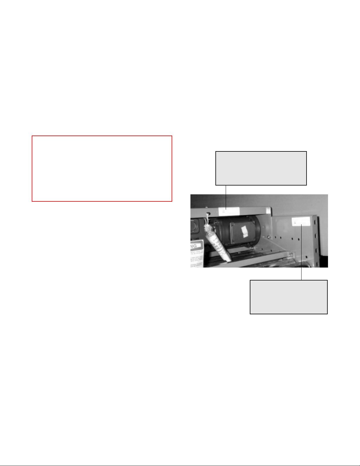
An identification label is attached to the inside of one
side channel close to one end of each conveyor bed
and on all drive packages. (See below.) This label
contains: job number, part number, order number, tag
number (if specified), assembler's initials and date of
manufacture. On supports, the tag is located on the
bottom side of the foot. On special devices it is located
on a convenient flat surface that is not offensive to the
appearance of the equipment but is still accessible for
viewing. These numbers can be cross-referenced
against the packing list. The illustrations in this manual
and the part number stickers will assist you with your
inventory.
Identification labels on
bed and drive package
IT#: 40084360
DSC: DR,CTR 24XR40 3/4 HP 60 B
JOB: C003325 11/10/96
mt
Loose parts are boxed and shipped separately. You
should have all conveyor sections and supports for a
particular conveyor prior to installation. It is cost-
effective to identify and procure any missing parts
before they are needed for assembly. Small items
like nuts and bolts are weigh-counted and packaged by
size and type.
IT#: X9503463
DSC: BED 24XR40-3D-X 10'
JOB: C003325 11/10/96
TAG: 101E
O-RINGS 90530005 90530009

9
90480006rev101210
TYPICAL XenoROL® LOOSE PARTS
Part Number Item Use Illustration
41700910
Line-shaft Guard End Cover
with Set Collar Kit
COVER with Set Collar, Kit
Cover End of Lineshaft at Termination of
Conveyor See WARNING Page 13
90140001 Safety Caps Cover End of Line-shaft Keyway See WARNING Page 20
90314510 Line-shaft Guard, 10' straight Guard Line-shaft See Page 33
41701000 Attaching Bracket Fasten Line-shaft Guard See Page 33
95200001 Spring Clip Nut 1/4 - 20 Fasten Line-shaft Guard See Page 33
95000021 Hex Head Flange Bolt 1/4-
20x3/4 Fasten Line-shaft Guard See Page 33
95300036 Rubber Washer Isolate Guard See Page 33
90480028 U-joint Cover Guard Horizontal to Incline, Straight Beds
90140025 Coupler Chain Line-shaft Coupling Bed to Bed See Page 20
Varies by Size Floor Support Support Conveyor Frames See Page 14
80400002 KBA Knee Brace Brace Frame to Support Leg See Page 15
80400003 KBB Knee Brace Brace Frame to Support Leg See Page 15
80400004 KBC Knee Brace Brace Frame to Support Leg See Page 15
80700001 Guard Rail Arm Support Adjustable Channel G.R. See Page 34
80700006 Guard Rail Upper Bracket Fasten Adjustable Channel G.R. to Arm See Page 34
80700007 Guard Rail Lower Bracket Fasten Arm to Frame See Page 34
80700011 Guard Rail Splice Angle Support Rail to Rail Joint See Page 34
95000027 1/4-20 Bolt x 2" Hex Head Upper Bracket to Channel G.R. See Page 34
95000075 3/8-16 x 1" Hex Head Bolt Lower Bracket to Frame and Brackets to
Arm See Page 34
95000020 1/4-20 x 3/4" Hex Head Bolt Splice Angle to Channel Guard See Page 34
95200050 1/4-20 Nuts Adjustable Channel G.R. See Page 34
80700112 Spacer Channel Ceiling Hanger See Page 16
80700013 V-Bracket Ceiling Hanger See Page 16
Varies b y
Length Cross Pipe Ceiling Hanger See Page 16
80701011 Standhead Connector Bed Joints See Page 15
40700051 Butt Bolt Connectors Bed Joints See Page 15
Special Connector Devices Per Application
Electrical Components Per Application
Special Device Parts Per Application
95000072 3/8-16 x 3/4 Hex HD Bolts Butt Bolts, Braces, Supports
95000074 3/8-16 x 3/4 Truss HD Bolts Angle Guard Rail
95200061 3/8-16 Nuts Angle Guard Rail
90530009 O-ring Drive Belts Rollers on discharge end of beds 24" wide
or more
90530005 O-ring Slave Belts Roller to roller belts at bed joints
80701002 2" Angle Guard Rail Straight conveyor
Varies by width Inside & Outside Angle G.R. Curves
Varies by width Rollers for beds 24" wide or
more*
Carrying rollers mounted in hex frame
holes
* Rollers for 30" wide conveyor and wider are shipped as loose parts.
Components for pneumatic options, including solenoid valves, fittings, air lines and mounting brackets are shipped as loose parts.

10
90480006rev101210
GENERAL PROCEDURES
After the first elevation is established at a critical point,
the elevation of all other points shall be relative to
this first point. Normal practice is to dimension the
layout and measure elevations from the floor at each
point of support. As the conveyor system proceeds
onto another floor or into another building or room, a
new elevation will be measured from the floor at that
point. This new elevation will then become the
reference for subsequent elevations.
When installing an overhead system, the first eleva-
tion is measured from the floor and becomes the
reference elevation point until a change in elevation is
shown on the layout. Any new elevation is also
measured from the floor and becomes the new refer-
ence point. The process is repeated each time an el-
evation change occurs.
The following procedures are to be used as guidelines
only for conveyor installation. Specific methods will vary
somewhat depending on available equipment on site
and each installer's preferences based on past experi-
ence.
WARNING
The Installation Supervisor must be experi-
enced with conveyor and qualified in the
mechanics of the equipment and enforce
safe working procedures for the protection
of the crew, customer, and customer's prop-
erty.
CAUTION
Consult the building architect or a struc-
tural engineer regarding ceiling loading or
structural limitations of the building if any
conveyor is ceiling hung.
COMPONENT ORIENTATION
Using your conveyor system layout drawing and the
numbers on the I.D. tags on each component, position
and orient the conveyor sections. You must know:
• The direction of product flow
• The elevation height
• How the drive is positioned
• Conveyor drive shaft location
• Any speed differential in jump chains
• Drive termination points
Note: IMPORTANT! Use extreme care when initially
orienting line-shaft conveyor components. Each line-
shaft conveyor section must be properly oriented to
ensure correct coupling to the next conveyor section.
For example, using the wrong jump chain bed or wrong
orientation may cause the following conveyor to run at
the wrong speed.
IMPORTANT! Do not make alterations to the equip-
ment without consulting with user's representative and
Ermanco. Unauthorized modifications to the equipment
may impair its function, create a hazardous condition,
affect its useful life and/or void the warranty. IMPOR-
TANT! At drive termination points, the coupler sprock-
ets must be removed before the section is installed.
DIMENSIONAL REFERENCE POINTS
The path of each conveyor in the system is determined
by establishing a reference point at each end. The cen-
ter line of the conveyor is established and a chalk line is
snapped between these points.
Conveyors should be installed with the center line of
the bed matching the center line of the conveyor path.
Locate and mark the center of the crossmembers at
each end of the conveyor. Use a plumb line or other
acceptable means to ensure accuracy to the chalk line.
Always carry out a thorough check for any obstructions
such as building columns, manholes, etc. It may be
necessary to reroute the conveyor to avoid the obstruc-
tion. In this case it would be advisable to begin installa-
tion at this point, using the obstruction as a reference
point (Datum), and install the sections in either direc-
tion as required.
All conveyor sections must be checked for squareness
prior to installation as "racking" or being knocked out of
square may have occurred during shipping and han-
dling. (Reference page 19.)
ELEVATIONS
All conveyors should be installed in accordance with
the elevations shown on the drawings. In addition, all
conveyors must be level across the frame width and
length (if horizontal). Leveling of the frames is best
done using a rotating laser level or a builder's level.
11
90480006rev101210
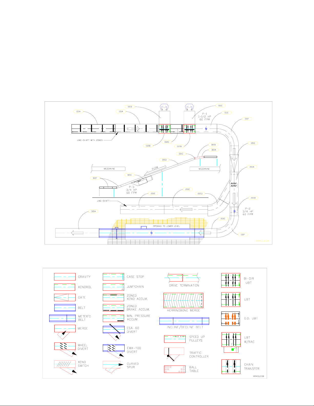
TYPICAL LAYOUT/LEGEND
Illustrated below is a hypothetical layout of an Ermanco
conveyor system. The dimensional data has been left
off for clarity. This layout is made up of a combination
of symbols from the legend as found on TGW Systems'
TECAP program layout software. This is typical of a lay-
out that would be received from Ermanco or any dis-
tributor using this software.
The layout you have received may or may not have the
match mark tag numbers as indicated in the balloons.
If your layout is tagged, these ballooned numbers will
match the tag number on each bed assembly or device.
(Ref. pg. 8). If the layout is not match marked, care must
be taken to see that the right device or drive, etc. is lo-
cated properly. Drive information, including horsepower
and speed, should be noted on the layout. Also shown
symbolically are positions of line-shafts, jump chains,
zero pressure zones, transfer flow direction, etc.
LAYOUT
LEGEND

12
90480006rev101210
LAYOUT DIMENSIONS
In laying out the conveyor path, the dimensions shown on
this page indicate the relative position between parallel or
perpendicular conveyors in utilizing a spur. For example,
dimension "G" indicates the center-to-center distance of
two parallel conveyors offset through a specific spur de-
gree and width when used with a corresponding curve.
As shown in the chart, dimension "E", the length of the
spur, is determined by the conveyor width which directly
affects dimensions "G" and "D" or "J" and "H". Normally,
merging takes place at 45° while most diverting devices uti-
lize 30°. Reference the overall layout to determine which
set of dimensions to use.
Since the original system layout will have already taken
these dimensions into account, they are most useful in
making future changes to the system. Note: These dimen-
sions do not include the wheel diverter. (Ref. page 26).
30° SPUR DIMENSIONS (In Inches)
A" B" C" D" E" F" G" H" I" J"
15-1/2
18-1/2
24-1/2
72
72
96
26
26-1/4
27-1/4
80-1/4
81-3/4
95-1/8
36
36
48
19
19-3/4
25-1/2
24-3/4
25
32
56
57-3/8
66-1/4
59
59-3/4
71-1/2
80-1/4
81-3/4
95-1/8
30-1/2
36-1/2
42-1/2
96
120
120
28
28-3/4
29-3/4
108-1/2
122
135-3/8
60
72
84
32
38-1/2
44-7/8
38-3/4
45-3/4
52-3/8
75-1/4
84-1/2
93-3/8
83-1/2
95-1/4
107-1/2
18-1/2
122
135-3/8
45° SPUR DIMENSIONS (In Inches)
A" B" C" D" E" F" G" H" I" J"
15-1/2
18-1/2
24-1/2
72
72
96
27-1/4
27-3/4
29
76-1/2
87-1/8
91-3/8
24
36
36
19-1/4
28
28-1/4
31-3/4
41
42-3/4
49-1/2
59-1/4
62-1/4
46-1/2
56
58-1/4
59
69
72
30-1/2
36-1/2
42-1/2
96
120
120
30-1/2
31-1/2
32-3/4
104
108-1/4
121
48
48
60
38-1/2
39-1/2
48-3/4
53-1/4
54-3/4
65-1/4
73-3/4
76-3/4
88-1/2
69
71
81-1/2
83-1/2
86-1/2
97-3/4

13
90480006rev101210
Never leave unused sprockets on line-shaft.
WARNING
Safety caps are required on ends of all ad-
joining line-shaft conveyor beds not
coupled together.
When continuing drive, install coupler
chain per instruction on pages 19 and 20.
LINE-SHAFT TERMINATIONS
End
Cover
in position
Set Collar
At joint between adjacent drive units, remove
sprockets and add white plastic safety caps.
WARNING
At the termination of the XenoROL ® line-
shaft driven conveyor(s), the open end of
the line-shaft guard must be covered with
the end cover kit provided in the loose
parts. This kit includes instructions,
mounting hardware and 1" bore set collar.
The set collar replaces the unused coupler
sprocket. This end cover must be used at
all exposed ends including XenoROL ter-
minations abutting other types of conveyor
or machinery.
WARNING
Remove any coupler sprocket which is not
coupled to an adjacent sprocket. These
sprockets must be removed BEFORE the
bed is installed. The white line-shaft safety
caps must be installed in place of the
sprockets to cover the end of the keyway.
14
90480006rev101210
FLOOR SUPPORTS
Install bolts used to attach the standhead to the frame
so the nut is on the bottom. Standhead bolts should
be left finger tight while the conveyor is being as-
sembled and aligned.
There are various frame rail depths depending on options
and accessories. Floor supports are ordered by nominal
height range, which is the dimension from the floor to top of
the support. Conveyor elevations are shown on the layout
by top-of-roller elevations. This difference must be recog-
nized when setting the support elevations. XenoROL
® con-
veyor is 4-7/8" from top-of-support to top-of-rollers with a
4-1/2" deep frame channel.
It is important that conveyor frames be installed level.
Floor supports will accommodate normal irregularities
in the floor surface. Adjustment for elevation in floor
supports is accomplished with metal-on-metal bolt
clamping force. To achieve the support's st ated load
rating, it is necessary to tighten the elevation adjust-
ment bolts (3/8" diameter) to 23 ft.lbs. of torque.
Supports should always be installed in the vertical position,
and any variations due to conveyor pitch or floor slope will be
compensated for in the pivoting standhead of the support.
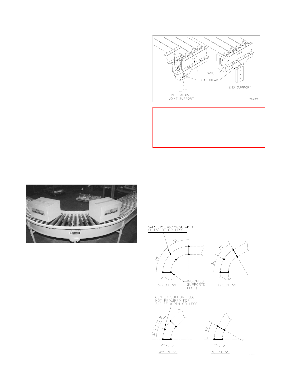
90° curve with true taper rollers. A single support leg is
located on the center of the outside channel. Over 18" width
should have full support.
ANCHORING
Anchoring in concrete floors is accomplished by drilling into
the floor and inserting the suitable anchor bolt. The hole
diameter and depth must be in accordance with the anchor
bolt manufacturer's instructions.
Anchor intermediate floor supports with two anchor bolts,
one through each support foot plate using minimum 3/8" di-
ameter anchor bolts. For floor supports over 5' high or when
supporting drives, use 1/2" diameter anchor bolts.
Stagger anchors from front hole on one side to rear hole on
opposite side. Anchor bolts for equipment subject to impact
loads should be a minimum of 1/2" diameter.
SUPPORTING ARRANGEMENTS
WARNING
Place a bolt through the frame and support
immediately with finger tight nut. This will
prevent the frame from falling off the sup-
port, if bumped, and causing injury.
CURVE SUPPORT POINTS - The curve illustration be-
low indicates proper support locations for curves of vari-
ous degrees and widths. The dots illustrate the support
connecting point to the conveyor. The dark line between
dots indicates a full support with welded crossmember or
ceiling hanger cross tube. A single dot on the outside
center of the curve indicates only the outer curve rail is
supported with either a ceiling hanger drop at that point
or a single leg floor support. If a full width support with
welded crossmember is supplied where only a dot is indicated,
use the full support. The illustration below is minimum
supporting arrangement.
15
90480006rev101210
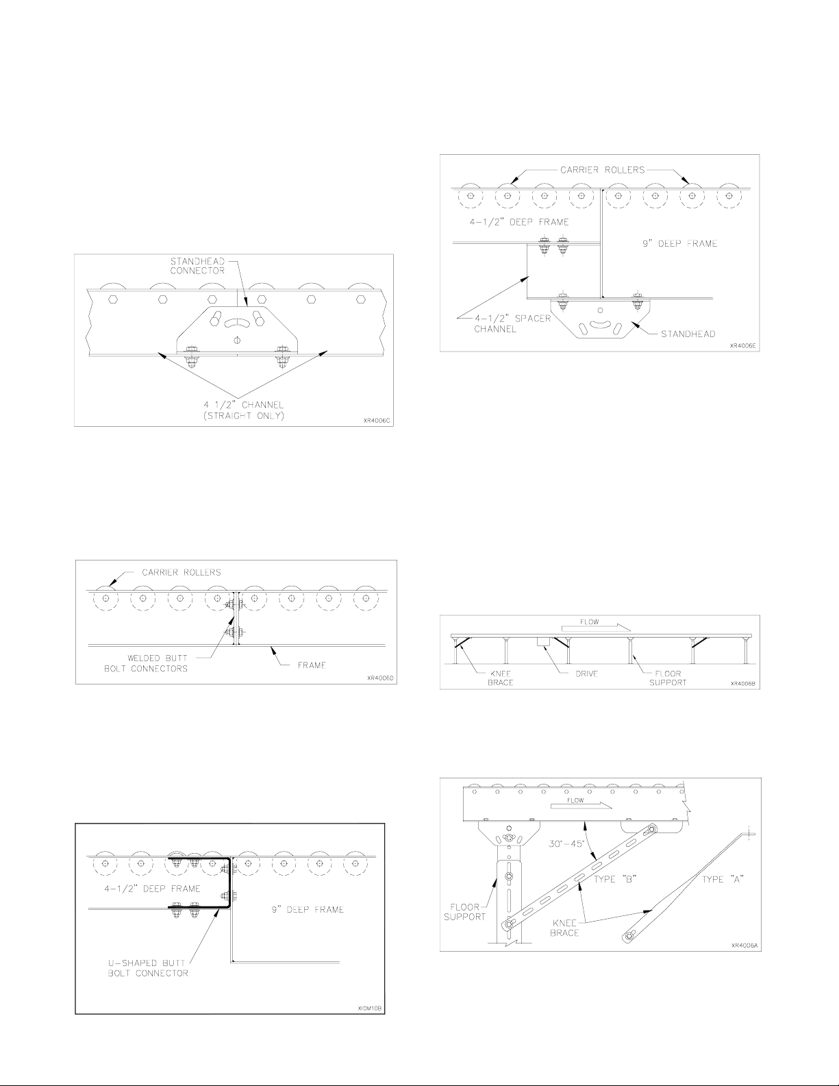
CONNECTORS
Adjoining beds may be connected using optional stand-
head connector plates (one on each side). Connectors
are normally used with ceiling hangers when the hanger
is not centered on the frame joint. The hanger should
be within 1' of the joint while maintaining 10' maximum
centers. The beds should be temporarily supported
while the support and connectors are installed.
Each standhead connector uses two bolts through the
flange of the frame plus two bolts through the vertical
leg and conveyor channel web.
Beds should be checked for squareness before
final tightening of bolts.
Welded butt bolt connectors may be used to join two straight
frames, straight to curve, straight spur or 4-1/2" to 9" deep
frame (urethane belt transfers). Welded butt bolt connectors
must be ordered on designated bed frames.
The spacer channel connector kit consists of two formed
channels 4-1/2" deep with mounting hardware. This
connector is a standard component of ceiling hangers
but is also used to allow a support on the frame joint
between 4-1/2" and 9" deep channel frames. This is
another choice to join a 4-1/2" channel to a UBT frame.
Welded butt bolt connector available for 4-1/2" deep
frames. They are standard with 9" deep frames.
U-shaped butt bolt connectors are commonly used to con-
nect a 4-1/2" channel frame to a urethane belt transfer which
uses a 9" deep frame. The UBT has pre-welded butt bolt
plates in each end.
A 4-1/2" deep spacer channel bolts to bottom flange of
4-1/2" deep bed and standhead of the floor support or a
ceiling hanger.
KNEE BRACES
Stability along the conveyor length is achieved with knee
braces. Braces resist stresses caused by direction of prod-
uct flow, drives, stop s and st arts. Every support does not
require bracing. Braces are used at the ends of straight runs
and approximately every 30' in between. Braces should be
located toward the discharge end (DOWNSTREAM) side
putting them in tension. Starting the conveyor puts oppo-
site stresses on the supports, which is resisted by in-
stalling a brace near the drive toward the receiving end
(UPSTREAM).
For best results the angle between the knee brace and
frame should not exceed 45 degrees, or be less than 30
degrees. On short supports where a small angle results,
the knee brace may need to be shortened.
Type "C" braces (not shown) use two type "B" braces
overlapped and bolted together for extended length
when conveyor height is 48" or more.

16
90480006rev101210
After hanger uprights are installed and the heavy ex-
tension nuts welded to angle hangers, thread the drop
rods into the extension nuts. Thread the jam nuts and
stop nuts on the drop rods far enough up the rods to
allow installation and adjustment of the cross pipe.
While still on the floor, loosely attach cross pipe, V-brack-
ets, flat strap connectors and bed connector to one end
of a bed section. Hoist the bed section between the
drop rods guiding the rods through the mounting holes
in the cross pipe. Thread the weld nuts on the drop
rods to support the bed. Weld the weld nuts to the drop
rods to prevent loosening. Hoist the next bed section
into place and connect it using the flat strap connectors
and V-brackets. Level the bed lengthwise and side to
side by threading the drop rods up or down by using a
wrench on the weld nuts. Tighten the jam nuts against
the extension nuts and the stop nuts against the cross
pipe. Continue for the length of the conveyor.
Drop rods and nuts are optional. The extension nut is
welded into the angle hanger upright during installation.
WARNING
Consult the building architect or a struc-
tural engineer regarding ceiling loading or
structural limitations of the building for siz-
ing header steel.
Cross pipes, V-brackets and flat strap connectors are
provided with ceiling hangers. Threaded 3/4" rod and
attaching nuts are available as an option. Bed connec-
tors are recommended with all ceiling hanger applica-
tions.
If hanger uprights are field fabricated, they should be a
minimum of 1-1/2" x 1-1/2" x 3/16" angle.
WARNING
Consult your distributor or a structural engi-
neer to determine what size hangers should
be used to support your maximum antici-
pated load.
CEILING HANGERS

17
90480006rev101210
SWAY BRACING (CEILING HANGER)
1. Sway bracing should be a minimum of 1-1/2" x
1-1/2" x 3/16" angle.
2. Sway bracing is secured to the hanger upright near
the conveyor support and extended upward at an
angle of approximately 30 degrees from the hanger
upright. The sway brace angle should not be over
45 degrees to the upright. When hangers are in-
stalled adjacent to building columns, a horizontal
brace may be installed securely to the column.
3. Hanger uprights over 12'-0" in length must have
horizontal bridging angles connected between the
upright and the sway brace at approximately the
half way point.
4. Sway bracing should be installed on every third
hanger (maximum of 30'-0" centers).
5. If sway bracing cannot be placed on the outside of
the uprights, alternate X-bracing between every
other pair of uprights.
6. Additional bracing should be used:
• Before and after curves
• At drives
• At product diverting points
DIAGONAL SWAY BRACE (FLOOR SUPPORT)
Floor support sway bracing consists of one 1-1/2" x
1-1/2" structural angle and mounting hardware.
APPLICATION: Due to natural side to side movement
of line-shaft conveyor, a diagonal sway brace has been
designed to reduce side movement in the standard
floor support. Side movement is most prevalent in long
straight lines which are not side braced by adjoining
conveyors, curves, etc. or where they cannot be
braced to columns, machinery, or other conveyors.
This is more noticeable when the conveyor elevation
is greater than its width. One brace can be mounted to
every third or fourth support diagonally across the sup-
port with the low end on the opposite side of every
other brace (alternate orientation). The holes in the
support uprights need to be field drilled.
If excessive oscillation persists after bracing has been
added, it may be the result of harmonics. This can
occur when the conveyor operating speed generates
vibrations with a frequency at or near the conveyor's
natural frequency of its structure. This rare condition
normally occurs between 85 FPM and 120 FPM. It
may be minimized by adding more bracing or by either
increasing or decreasing conveyor speed.
Sometimes it is better not to add a brace at the drive
location. Some experimentation may be required.
CAUTION
Before adding X-braces between uprights,
check for adequate product clearance.

18
90480006rev101210
MULTI-LEVEL XENOROL® SUPPORT
To mount XenoROL to multiple level supports, bolt two
V-brackets and two spacer channels to each horizontal
crossmember. Measure from the floor to the top of the
spacer channels, set the crossmember to the desired
elevation minus the distance from the bottom of the
frame to the top of the rollers. Tighten the bolts only
enough to hold the crossmember in place.
Set up two multiple deck supports and, starting with the
lowest line, bolt the ends of a frame to the spacer chan-
nels. On the end beds, install one support completely
on the frame so that the center of the upright is 6" from
the end of the frame. All intermediate supports are in-
stalled and centered on the joint.
After three supports and beds are installed, make final
elevation adjustments and level the beds lengthwise
and side to side. Securely tighten the crossmember
bolts. Continue for the length of the conveyor.
Clamping of stringers or headers to building trusses will nor-
mally be done only at panel points. Specific customer per-
mission and load calculations by a qualified engineer are
necessary to safely clamp between panel points.
Headers when used for short spans, such as between roof
purlins, will be securely clamped to building steel. Stringers,
when used between headers, may be welded or bolted to
the headers directly or with suitable angle clips.
Concrete Ceilings
Accomplish anchoring by drilling into the concrete ceil-
ing and inserting suitable anchor bolts. The hole diam-
eter and depth must be in accordance with the lag bolt
manufacturer's instructions.
Anchor each hanger with four bolts (two per upright)
minimum size 1/2" diameter. Consult your distributor
or structural engineer to determine your needs.
WARNING
Do not use explosive type anchors.
For heavier concentrated loads like drives or points
where movement or vibration can occur , use 5/8" di-
ameter through bolts with backup plates. If this is not
permissible or possible, then header steel must be in-
stalled using several anchor bolts to spread the load.
Wood Joists/Beams
Hangers may be attached directly to the joists provid-
ing the load rating of the building will permit. Attach
hangers to the vertical side of the joist in two places,
one above the other, on each hanger upright. Anchor-
ing is accomplished by drilling through the joist in the
upper position and using a 1/2" diameter through bolt
with a backup plate or heavy washer. A 1/2" diameter
lag screw may be used in the lower position.
When a header is required to support the load, it must
bridge across two or more joists. This header will be
attached to each joist in the manner specified in para-
graph above. Hanger uprights should then be bolted or
welded securely to the headers. Consult a structural
engineer to determine which method should be
used for your load requirements.
Concrete/Masonry Walls
Equipment may be supported from concrete walls through
use of suitable bolts and anchors or by bolting through the
wall if the condition of the wall or load dictates it. A
1/2" diameter through bolt should be used with a backing
plate.
METHODS FOR ANCHORING CEILING HANGERS
Open Building Steel
The following references are from the American Insti-
tute for Steel Construction manual (AISC).
Welding of auxiliary steel (stringers or headers) to build-
ing steel is prohibited.
Drilling and bolting to building steel is not recommended
and will be done only with the customer's written per-
mission.
Note: Flat strap across joint is required when spacer
channel is not used.
19
90480006rev101210
BASICS OF XenoROL®INSTALLATION
GENERAL
FRAME ALIGNMENT
Conveyor frames must always be installed in a straight
line from end to end as described in GENERAL PRO-
CEDURES. After a number of sections have been
installed to the chalk line and leveled, check the align-
ment of each line-shaft assembly. As the conveyor sec-
tions are bolted together, the coupler sprockets may
require adjusting. The edge of the 1" diameter line-
shaft must be 2" from the frame channel to start.
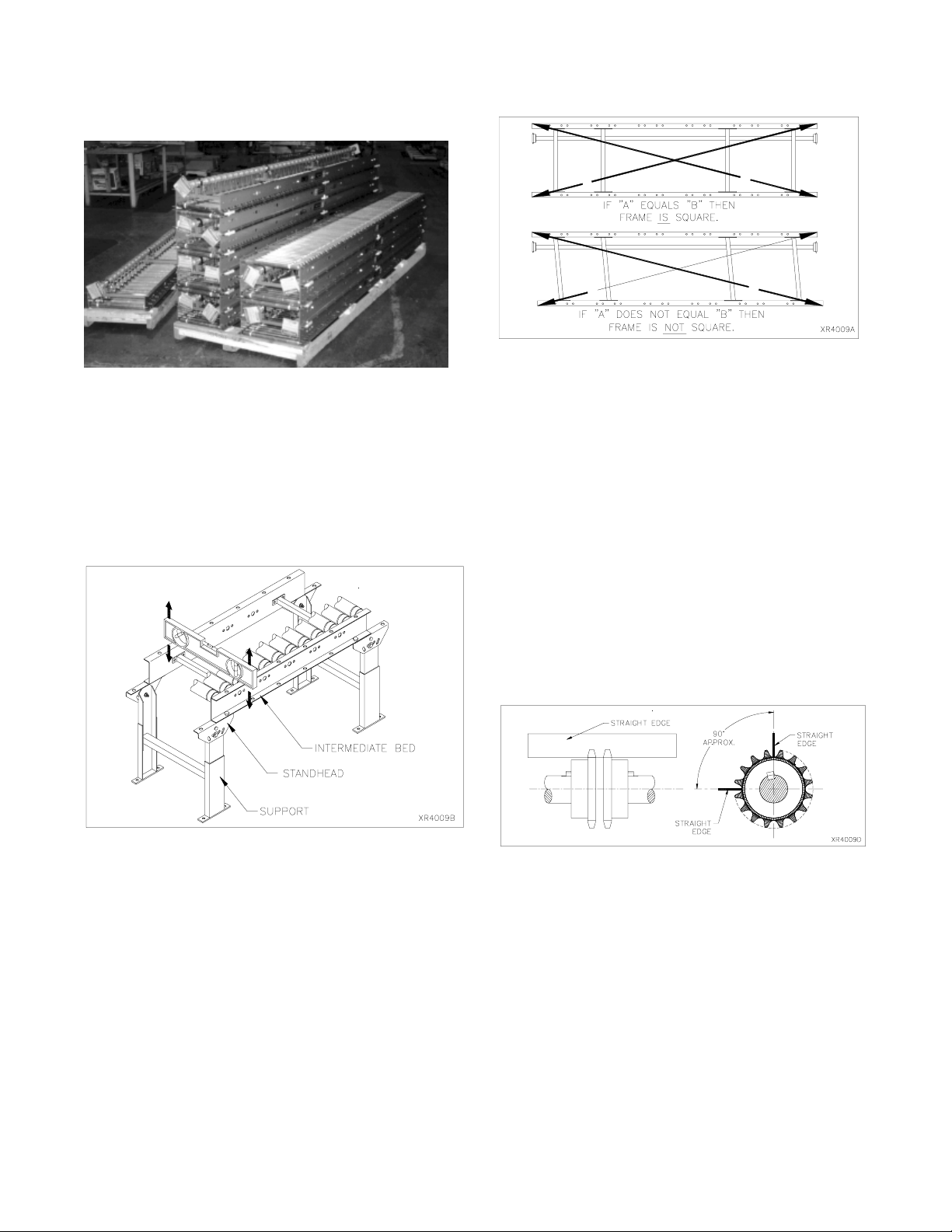
COUPLER ALIGNMENT
Check the alignment of each pair of coupler sprockets.
Parallel alignment can be checked with a straight edge
placed on the two sprockets at the root of the teeth.
Alignment should be checked in at least two places, at
90 degree intervals. The straight edge must appear
level to the coupler hubs or line-shaft. This will put par-
allel alignment within the specified .005" limit.
If it becomes necessary to shorten a bed frame, cut the
end bed where a coupler is not needed, if possible. If
the drive must be continued, it is best to disassemble
the line-shaft assembly and re-keyway the line-shaft's
cut end. If only a small amount of conveyor is driven by
the cut bed, the coupler sprocket may be field welded
or pinned to the cut end of the shaft.
When joining bed frames it is important to align the roll-
ers and line-shaft. Care must be taken to make sure
the rollers are level (carrying surfaces) from bed to bed.
All bed frames should be checked for squareness. To
check, measure diagonally from corner to corner. Mea-
sure the opposite corners in the same manner. If the
bed is square, the two measurements will be the same
within 1/16".
If the coupler sprockets do not align vertically, adjust
either or both of the following:
1. Loosen the crossmember mounting bolts of two
crossmembers in each bed and adjust the height
of the crossmember within the limits of the mount-
ing holes.
2. Insert shims between the bearing housing and the
bearing hanger of the crossmember.
Tip: Loosen one coupler sprocket and slide it against
the other. Adjust the line-shaft for zero gap between
sprocket faces and exact mating of teeth. Then move
loose sprocket back 9/32" and tighten set screws to 13
ft.lbs.
XenoROL®bed sections stacked on pallets for shipping
(7) intermediate beds per side.
Straight bed sections may be installed using any of the
support methods previously described (see SUPPORT-
ING ARRANGEMENTS). As each bed is installed in
the system, level it lengthwise and across the bed width
on a roller. The supports should also be checked for
vertical. A shorter level may be required to check the
upright without the level overlapping the lower boot.
B
A
AB
This manual suits for next models
1
Table of contents
Other TGW Accessories manuals


Popular Accessories manuals by other brands


FRONIUS
FRONIUS OPT/i WF R installation instructions

Siemens
Siemens SITRANS WS300 operating instructions

Byron
Byron SX-80 Installation and operation instruction

Pogo Bounce House
Pogo Bounce House Tropical Marble 35' Dual Lane Slip N Slide manual

Panasonic
Panasonic KX-HNS104FX installation guide

Interlogix
Interlogix SDX-135Z-433 user guide


