TGW IntelliROL Power Supply 1166694PULS Use and maintenance manual

Application Control Guidelines
IntelliROL®Power Supply™
P/N 1176718
Revision Date: February 17, 2021

P/N: 1176718 REV: 02/17/2021 Page 2of 32
TABLE OF CONTENTS
LIST OF TABLES ......................................................................................................................................... 3
1.1: TGW SAFETY RECOMMENDATION ......................................................................................................... 4
CHAPTER 2: WARNINGS AND SAFETY INSTRUCTIONS ....................................................................... 6
CHAPTER 3: INTRODUCTION .................................................................................................................... 7
3.1: OVERVIEW ........................................................................................................................................... 7
CHAPTER 4: TGW PARTS LIST ................................................................................................................. 8
CHAPTER 5: FEATURES .......................................................................................................................... 11
5.1: ALL INTELLIROL POWER SUPPLIES ..................................................................................................... 11
5.2: POWER SUPPLY FEATURES................................................................................................................. 12
5.3: DIAGNOSTIC RELAY ............................................................................................................................ 13
5.4: TERMINAL STRIP CONNECTIONS .......................................................................................................... 14
CHAPTER 6: ITR COMBINATION POWER SUPPLIES ........................................................................... 15
CHAPTER 7: CONNECTIONS ................................................................................................................... 17
7.1: INTERNAL TO POWER SUPPLY ............................................................................................................. 17
7.2: AT CONVEYOR EQUIPMENT ................................................................................................................. 18
CHAPTER 8: APPLICATION ..................................................................................................................... 19
CHAPTER 9: STATUS INDICATORS........................................................................................................ 20
CHAPTER 10: TROUBLESHOOTING GUIDE .......................................................................................... 21
10.1: INTELLIROL STANDARD AND COMBINATION POWER SUPPLIES............................................................ 21
10.2: INTELLIROL COMBINATION POWER SUPPLIES.................................................................................... 23
CHAPTER 11: SPECIFICATIONS ............................................................................................................. 26
11.1: ITR STANDARD AND COMBINATION (480VAC INPUT) ......................................................................... 26
11.2: ITR STANDARD AND COMBINATION (208/240VAC INPUT) .................................................................. 27
11.3: ITR STANDARD AND COMBINATION (120VAC INPUT) ......................................................................... 28
11.4: CLASS 2PROTECTION MODULE......................................................................................................... 29
11.5: CRUZCONTROL TECHNICAL DATA..................................................................................................... 30
WORKS CITED........................................................................................................................................... 31
TGW GENERAL INFORMATION ................................................................................................................... 31
TGW SYSTEMS INFORMATION ............................................................................................................... 32

P/N: 1176718 REV: 02/17/2021 Page 3of 32
LIST OF TABLES
Table 1: IntelliROL Power Supply Listing ....................................................................................8
Table 2: IntelliROL Standard Power Supply Status Indicators ...................................................20
Table 3: IntelliROL Combination Power Supply Status Indicators .............................................20
Table 4: IntelliROL Standard and Combination Power Supply Troubleshooting Guide ..............21
Table 5: IntelliROL Combination Power Supply Troubleshooting Guide ....................................23
Table 6: IntelliROL Standard and Combination Power Supplies (480VAC Input).......................26

P/N: 1176718 REV: 02/17/2021 Page 4of 32
1.1: TGW SAFETY RECOMMENDATION
TGW Systems Equipment Warranty
TGW Systems warrants that the material and
workmanship entering into its equipment is
merchantable and will be furnished in accordance with
the specifications stated.
TGW Systems agrees to furnish the purchaser without
charge any part proved defective within 2 years from
date of shipment provided the purchaser gives TGW
Systems immediate notice in writing and examination
proves the claim that such materials or parts were
defective when furnished. For drive components
specific to XenoROL® (i.e. Xeno belts, slave Xeno
belts, drive spools, standard and speed-up, and
spacers), this warranty shall be extended to five years
of running use, provided the conveyors are applied,
installed and maintained in accordance with TGW
Systems published standards. Other than the above,
there are no warranties which extend beyond the
description on the face hereof. Consequential damages
of any sort are wholly excluded.
The liability of TGW Systems will be limited to the
replacement cost of any defective part. All freight and
installation costs relative to any warranted part will be at
the expense of the purchaser. Any liability of TGW
Systems under the warranties specified above is
conditioned upon the equipment being installed,
handled, operated, and maintained in accordance with
the written instructions provided or approved in writing
by TGW Systems.
The warranties specified above do not cover, and TGW
Systems makes no warranties which extend to, damage
to the equipment due to deterioration or wear
occasioned by chemicals, abrasion, corrosion or
erosion; Purchaser's misapplication, abuse, alteration,
operation or maintenance; abnormal conditions of
temperature or dirt; or operation of the equipment
above rated capacities or in an otherwise improper
manner.
THERE ARE NO WARRANTIES, EXPRESSED OR
IMPLIED, INCLUDING, BUT NOT LIMITED TO,
WARRANTIES OF MERCHANTABILITY OR FITNESS
FOR A PARTICULAR PURPOSE, EXTENDING
BEYOND THOSE SET FORTH IN THIS STATEMENT
OF WARRANTY.
Rev 03/01/2019
TGW Environment Standards
TGW equipment is designed to be installed in
a clean, dry warehouse environment.
Exposure to extreme humidly, direct sunlight,
blowing dirt or rain can permanently damage
some components of TGW conveyor. In
particular, the curing agents in concrete are
known to attack and degrade the urethane
conveyor components.
When installing conveyor on a new
construction site, be sure that the concrete is
properly cured before setting conveyor on it.
In addition, if conveyors are stored in the
proximity of curing concrete, proper
ventilation must be used to direct the curing
agent fumes away from the conveyor.
Failure to comply with these guidelines will
void the TGW warranty on any failed
components that result from these
environment issues.
03/01/2019
P/N: 1176718 REV: 02/17/2021 Page 5of 32
•Safety: Always lock out power source and follow recommended safety
procedures.
WARNING
P/N: 1176718 REV: 02/17/2021 Page 6of 32
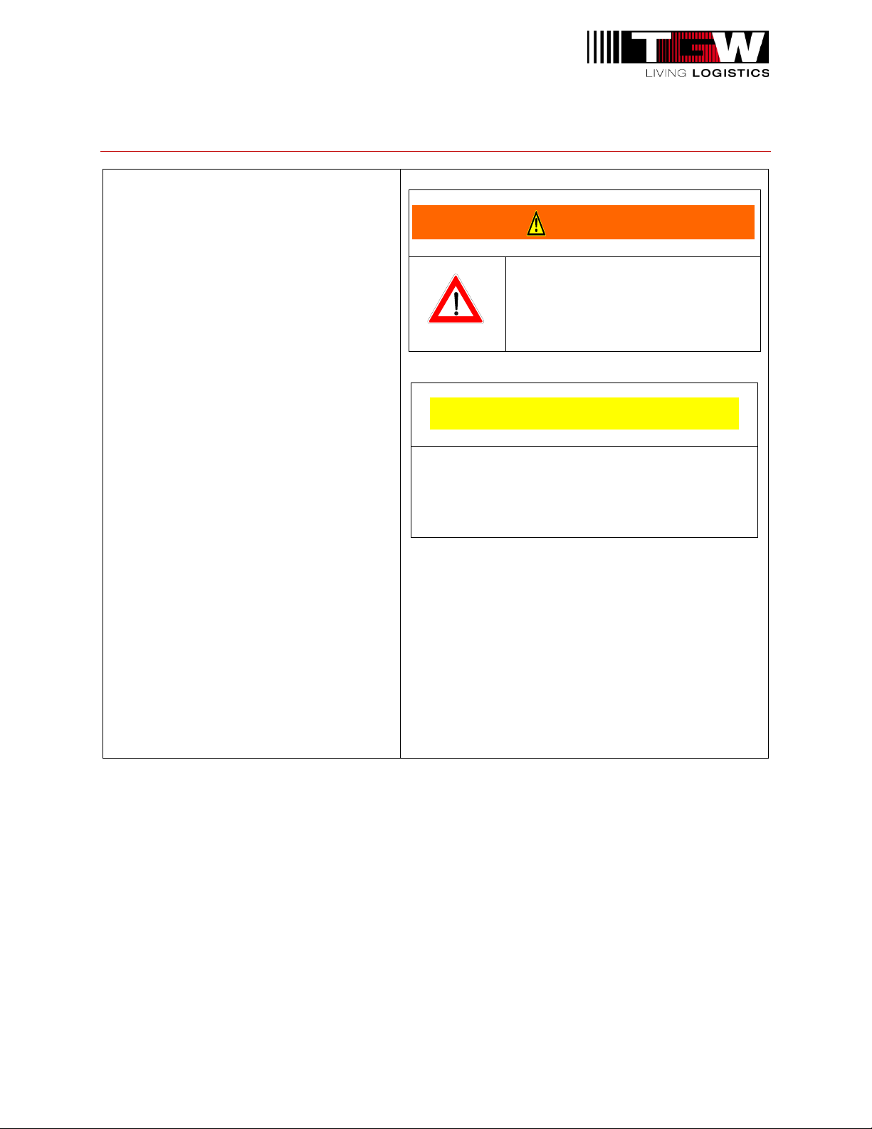
Chapter 2: WARNINGS AND SAFETY INSTRUCTIONS
Failure to follow the instructions and
cautions throughout this manual and
warning label on the conveyor may
result in injury to personnel or damage
to the equipment.
Your TGW Systems conveyor is
powered by a motor and can be stopped
only by turning off electrical power to the
motor. As with all powered machinery,
the drive-related components – including
sprockets, chains, shafts, universal
joints, and pneumatic devices – can be
dangerous. We have installed or
provided guards to prevent accidental
contact with these parts, along with
warning labels to identify the hazards.
Special attention must be paid to the
following areas of this manual:
•Indicates a potentially hazardous
situation, which, if not avoided,
could result in death or serious
injury.
•Indicates a situation, which, if not avoided,
could result in property damage.
WARNING
CAUTION

P/N: 1176718 REV: 02/17/2021 Page 7of 32
Chapter 3: INTRODUCTION
3.1: OVERVIEW
The IntelliROL product line includes power supplies that convert various AC power sources to
24VDC power sources. These power supplies are used to supply power to the motorized roller
components included in our IntelliROL product line. Power supplies are available for most
standard input voltages. Available output currents include 10, 20, 40 and 80 amperes.
IntelliROL power supplies are available with internal branch circuit protection. If branch circuit
protection is already provided upstream by others, IntelliROL power supplies are available
without internal branch circuit protection at a lower cost. All IntelliROL power supplies are
designed and built to UL508A standards. Refer to Table 1: IntelliROL Power Supply Listing for
a list of available power supplies.
P/N: 1176718 REV: 02/17/2021 Page 8of 32
Chapter 4: TGW PARTS LIST
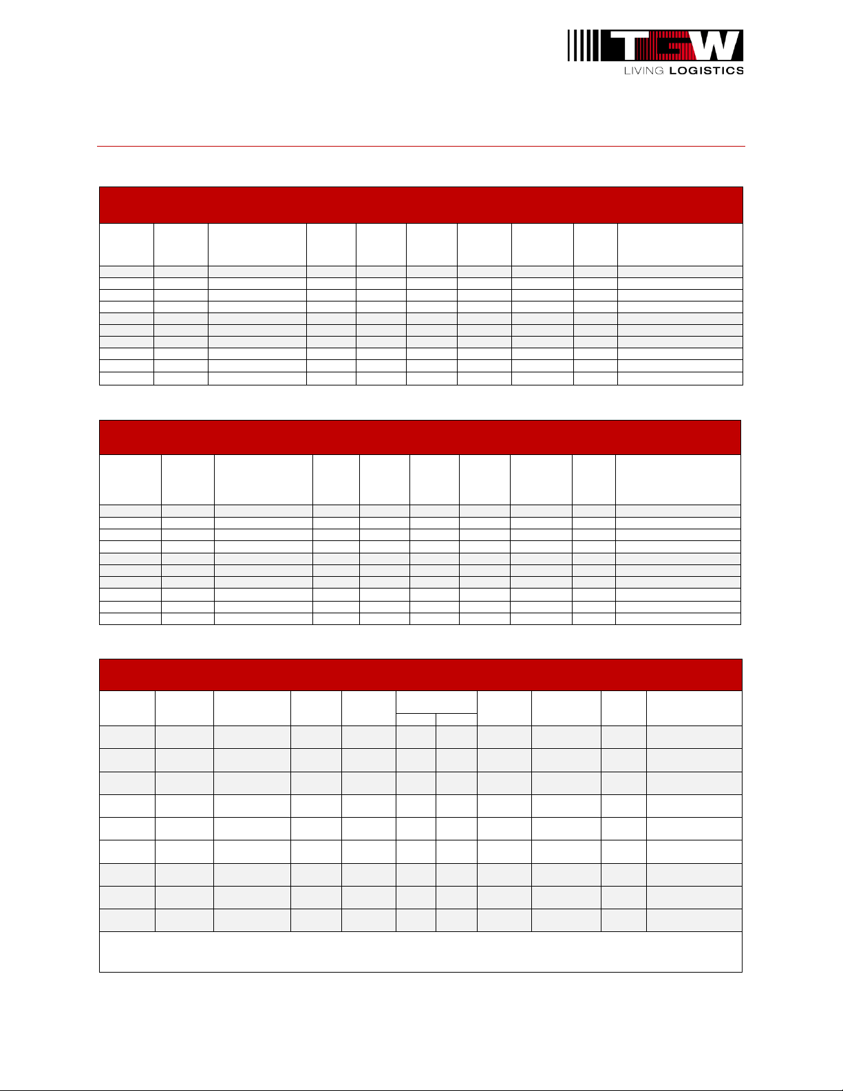
Table 1: IntelliROL Power Supply Listing
24VDC STANDARD POWER SUPPLIES WITH BRANCH CIRCUIT PROTECTION FOR INTELLIROL
TGW
Item
Number
Drawing
Number
Input Voltage
Power
Supply
Size
Input
Current
Output
Current
Number
of MDR
Enclosure
Type
UL
Listed
Enclosure Dimensions
(H x W x D)
1176603
130E233
480VAC/3PH/60HZ
80A
2.8A
80A
36
Type 12
Yes
15-3/4" X 15-3/4" X 7-7/8"
1160913
130E115
480VAC/3PH/60HZ
40A
1.4A
40A
18
Type 12
Yes
15-3/4" X 15-3/4" X 7-7/8"
1160948
130E117
240VAC/3PH/60HZ
40A
4.5A
40A
18
Type 12
Yes
15-3/4" X 15-3/4" X 7-7/8"
1160950
130E119
120VAC/1PH/60HZ
40A
8.6A
40A
18
Type 12
Yes
15-3/4" X 15-3/4" X 7-7/8"
1160915
130E116
480VAC/3PH/60HZ
20A
0.65A
20A
9
Type 12
Yes
15-3/4" X 15-3/4" X 7-7/8"
1160949
130E118
240VAC/3PH/60HZ
20A
2.23A
20A
9
Type 12
Yes
15-3/4" X 15-3/4" X 7-7/8"
1160951
130E120
120VAC/1PH/60HZ
20A
4.64A
20A
9
Type 12
Yes
15-3/4" X 15-3/4" X 7-7/8"
1166694
130E174
480VAC/3PH/60HZ
10A
0.6A
10A
3
Type 12
Yes
15-3/4" X 15-3/4" X 7-7/8"
1166695
130E175
240VAC/2PH/60HZ
10A
1.13A
10A
3
Type 12
Yes
15-3/4" X 15-3/4" X 7-7/8"
1166696
130E176
120VAC/1PH/60HZ
10A
2.15A
10A
3
Type 12
Yes
15-3/4" X 15-3/4" X 7-7/8"
24VDC STANDARD POWER SUPPLIES WITHOUT BRANCH CIRCUIT PROTECTION FOR INTELLIROL
TGW Item
Number
Drawing
Number Input Voltage
Power
Supply
Size
Input
Current
Output
Current Number
of MDR
Enclosure
Type
UL
Listed
Enclosure Dimensions
(H x W x D)
1176628
130E234
480VAC/3PH/60HZ
80A
2.8A
80A
36
Type 12
Yes
15-3/4" X 15-3/4" X 7-7/8"
1159645
130E121
480VAC/3PH/60HZ
40A
1.4A
40A
18
Type 12
Yes
15-3/4" X 15-3/4" X 7-7/8"
1160953
130E123
240VAC/2PH/60HZ
40A
4.5A
40A
18
Type 12
Yes
15-3/4" X 15-3/4" X 7-7/8"
1160955
130E125
120VAC/1PH/60HZ
40A
8.6A
40A
18
Type 12
Yes
15-3/4" X 15-3/4" X 7-7/8"
1159647
130E122
480VAC/3PH/60HZ
20A
0.65A
20A
9
Type 12
Yes
15-3/4" X 15-3/4" X 7-7/8"
1160954
130E124
240VAC/2PH/60HZ
20A
2.23A
20A
9
Type 12
Yes
15-3/4" X 15-3/4" X 7-7/8"
1160956
130E126
120VAC/1PH/60HZ
20A
4.64A
20A
9
Type 12
Yes
15-3/4" X 15-3/4" X 7-7/8"
1166697
130E177
480VAC/3PH/60HZ
10A
0.6A
10A
3
Type 12
Yes
15-3/4" X 15-3/4" X 7-7/8"
1166698
130E178
240VAC/2PH/60HZ
10A
1.13A
10A
3
Type 12
Yes
15-3/4" X 15-3/4" X 7-7/8"
1166699
130E179
120VAC/1PH/60HZ
10A
2.15A
10A
3
Type 12
Yes
15-3/4" X 15-3/4" X 7-7/8"
24VDC COMBINATION POWER SUPPLIES WITH BRANCH CIRCUIT PROTECTION FOR INTELLIROL AND CRUZCONTROL
TGW
Item
Number
Drawing
Number Input Voltage
Power
Supply
Size
Input
Current
Output
Current
Number
of MDR
Enclosure
Type
UL
Listed
Enclosure
Dimensions
(H x W x D)
ITR
CRUZ
1160917
130E103
480VAC/3PH/
60HZ
40A
1.4A
36
4
17
Type 12
Yes
15-3/4" X 15-3/4"
X 7-7/8"
1160919
130E105
240VAC/2PH/
60HZ
40A
4.5A
36
4
17
Type 12
Yes
15-3/4" X 15-3/4"
X 7-7/8"
1160921
130E107
120VAC/1PH/
60HZ
40A
8.6A
36
4
17
Type 12
Yes
15-3/4" X 15-3/4"
X 7-7/8"
1160918
130E104
480VAC/3PH/
60HZ
20A
0.65A
16
4
8
Type 12
Yes
15-3/4" X 15-3/4"
X 7-7/8"
1160920
130E106
240VAC/2PH/
60HZ
20A
2.23A
16
4
8
Type 12
Yes
15-3/4" X 15-3/4"
X 7-7/8"
1160922
130E108
120VAC/1PH/
60HZ
20A
4.64A
16
4
8
Type 12
Yes
15-3/4" X 15-3/4"
X 7-7/8"
1166700
130E180
480VAC/3PH/
60HZ
10A
0.6A
6
4
2
Type 12
Yes
15-3/4" X 15-3/4"
X 7-7/8"
1166701
130E181
240VAC/2PH/
60HZ
10A
1.13A
6
4
2
Type 12
Yes
15-3/4" X 15-3/4"
X 7-7/8"
1166702
130E182
120VAC/1PH/
60HZ
10A
2.15A
6
4
2
Type 12
Yes
15-3/4" X 15-3/4"
X 7-7/8"
Combination power supplies split the output current between the MDR supply and the Class 2 supply. The Class 2 supply can use up to
3.7A, in which case the MDR supply would have 36.3A available from a 40A supply.
P/N: 1176718 REV: 02/17/2021 Page 9of 32
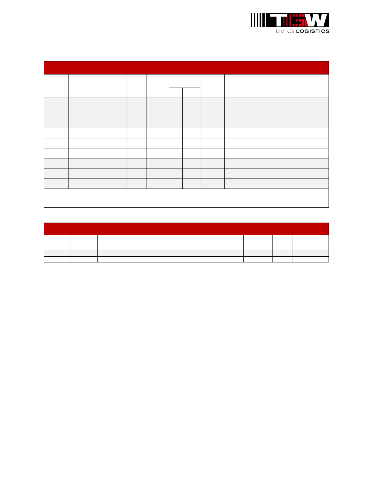
24VDC COMBINATION POWER SUPPLIES WITHOUT BRANCH CIRCUIT PROTECTION FOR INTELLIROL AND CRUZCONTROL
TGW
Item
Number
Drawing
Number
Input
Voltage
Power
Suppl
y Size
Input
Current
Output
Current
Number
of MDR
Enclosure
Type
UL
Listed
Enclosure Dimensions
(H x W x D)
IT
R
CRU
Z
1160923
130E109
480VAC/3PH/
60HZ
40A
1.4A
36
4
17
Type 12
Yes
15-3/4" X 15-3/4" X 7-7/8"
1160925
130E111
240VAC/2PH/
60HZ
40A
4.5A
36
4
17
Type 12
Yes
15-3/4" X 15-3/4" X 7-7/8"
1160927
130E113
120VAC/1PH/
60HZ
40A
8.6A
36
4
17
Type 12
Yes
15-3/4" X 15-3/4" X 7-7/8"
1160924
130E110
480VAC/3PH/
60HZ
20A
0.65A
16
4
8
Type 12
Yes
15-3/4" X 15-3/4" X 7-7/8"
1160926
130E112
240VAC/2PH/
60HZ
20A
2.23A
16
4
8
Type 12
Yes
15-3/4" X 15-3/4" X 7-7/8"
1160928
130E114
120VAC/1PH/
60HZ
20A
4.64A
16
4
8
Type 12
Yes
15-3/4" X 15-3/4" X 7-7/8"
1166703
130E183
480VAC/3PH/
60HZ
10A
0.6A
6
4
2
Type 12
Yes
15-3/4" X 15-3/4" X 7-7/8"
1166704
130E184
240VAC/2PH/
60HZ
10A
1.13A
6
4
2
Type 12
Yes
15-3/4" X 15-3/4" X 7-7/8"
1166705
130E185
120VAC/1PH/
60HZ
10A
2.15A
6
4
2
Type 12
Yes
15-3/4" X 15-3/4" X 7-7/8"
Combination power supplies split the output current between the MDR supply and the Class 2 supply. The Class 2 supply can use up to
3.7A, in which case the MDR supply would have 36.3A available from a 40A supply.
MOTOR CONTROL 24VDC POWER SUPPLIES FOR INTELLIROL (USED ONLY WITH MOTORS W/O VFD)
TGW Item
Number
Drawing
Number Input Voltage
Power
Supply
Size
Input
Current
Output
Current
Number of
MDR
Enclosure
Type
UL
Listed
Enclosure
Dimensions
(H x W x D)
1145931
130E043
480VAC/3PH/60HZ
20A
0.65A
20A
9
Type 12
Yes
12"X 12" X 8"
1145930
130E042
480VAC/3PH/60HZ
10A
0.6A
10A
3
Type 12
Yes
12"X 12" X 8"
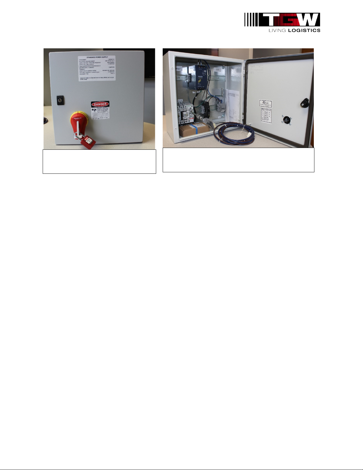
P/N: 1176718 REV: 02/17/2021 Page 10 of 32
IntelliROL Standard Power Supply,
External View
IntelliROL Standard Power Supply, Internal View

P/N: 1176718 REV: 02/17/2021 Page 11 of 32
Chapter 5: FEATURES
5.1: ALL INTELLIROL POWER SUPPLIES
Lockable Disconnect Switch
All IntelliROL power supplies include a lockable disconnect switch. This allows for lockout/tagout at the
power supply.
IntelliROL Power Supply Lockable Disconnect Switch
Internal Branch Circuit Protection
IntelliROL power supplies are available with internal branch circuit protection. If proper branch
circuit protection is not available upstream of the IntelliROL power supply, the power supply
should be purchased with branch circuit protection built in.
Output Current Boost
Each IntelliROL power supply can provide a boost in output current over its nominal rating. The
extra current is available for a short period of time. Since IntelliROL conveyor draws maximum
current at startup, this current boost is a definite advantage.

P/N: 1176718 REV: 02/17/2021 Page 13 of 32
5.3: DIAGNOSTIC RELAY
The power supply unit inside each IntelliROL power supply has a diagnostic relay that can be
used to monitor the status of the unit. When the unit is powered and functioning properly, the
diagnostic relay contact will be closed.
Adjustable Output Voltage
The output voltage of the power supply units is adjustable from 24V to 28.8V. This can be used
to possibly overcome a low voltage condition, as long as the maximum voltage at any point in
the system does not exceed specifications.
Status Indicators
Status indicators are provided on the front of the power supply units internal to every IntelliROL
power supply. The Uout status indicator will be illuminated green if the output voltage is 21.6V
or greater. It will be illuminated red if the output voltage is less than 21.6V and greater than or
equal to 7V. If the output voltage is less than 7V, the indicator will not be illuminated at all.
There is also an Iout status indicator on the front of the power supply units. It will be illuminated
green if the output current is less than or equal to the rated output current. If the output current
is greater than the rated output current, the indicator will be illuminated orange. The indicator
will be illuminated red if the unit is shut off and in protection mode due to excessive output
current.
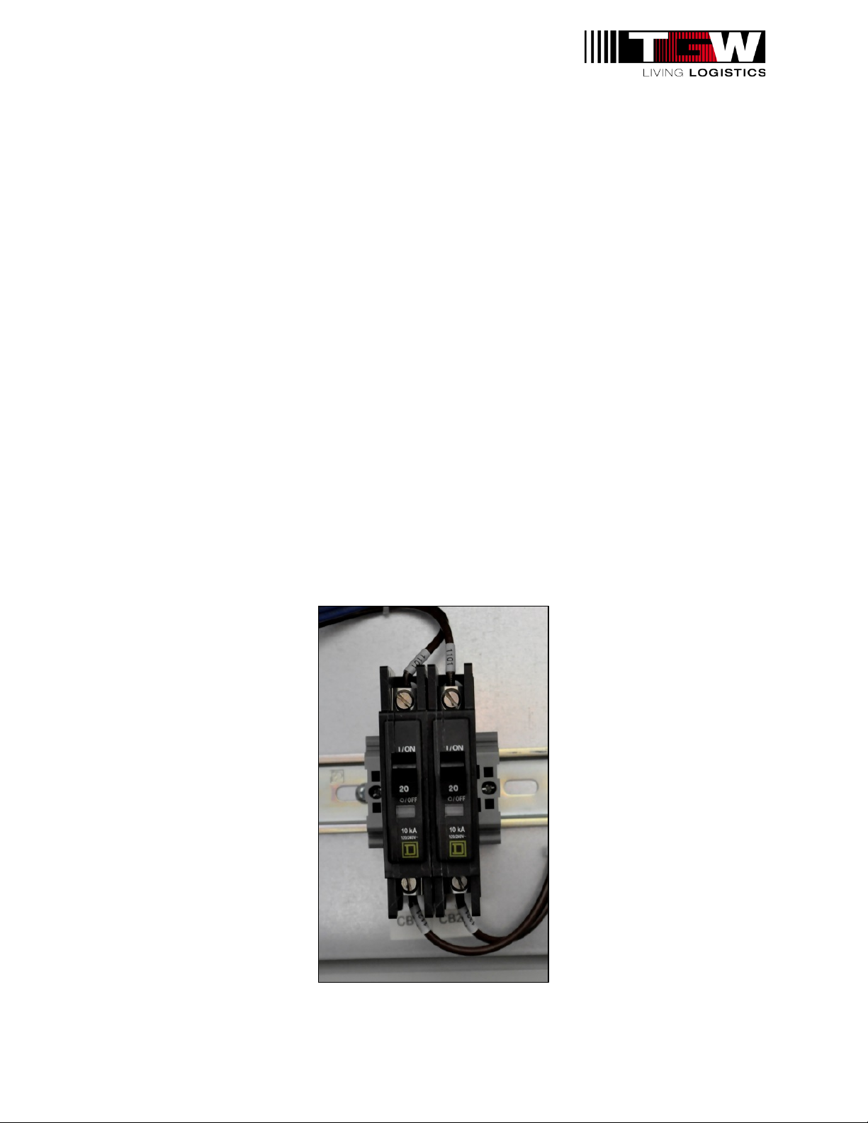
Output Circuit Protection
Every IntelliROL power supply includes circuit breaker protection of the output circuits. Power
supplies with a 10A output rating have one 10A circuit breaker. Units with a 20A output rating
have one 20A circuit breaker. Those with a 40A rating have two 20A circuit breakers, while
80A-rated units have four 20A circuit breakers.
Output Circuit Protection
P/N: 1176718 REV: 02/17/2021 Page 14 of 32
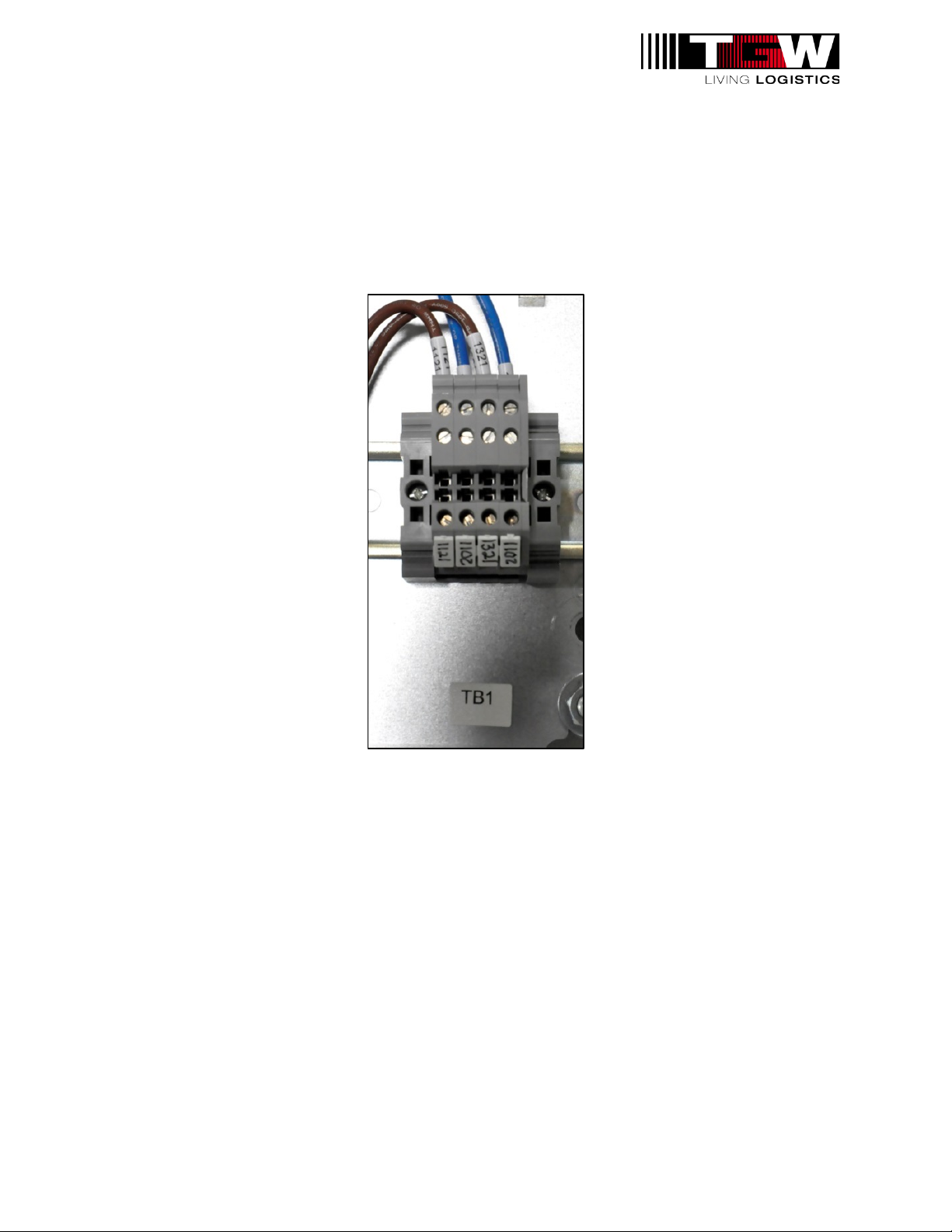
5.4: TERMINAL STRIP CONNECTIONS
All output circuit connections are made at a terminal strip. Each IntelliROL power supply has
separate terminals for two Class 1 circuits to supply power to the motorized rollers. For the
Combination power supplies, there are terminals for one Class 2 circuit to supply power to
nearby CRUZcontrol. A power harness is included with each IntelliROL power supply. This can
be used to connect the Class 1 circuits of the power supply to the power harness installed on
the IntelliROL conveyor.
IntelliROL Power Supply Terminal Strip
Splice Kit
A power splice kit is included with each IntelliROL power supply. The splice kit is used to
connect the Class 1 circuits of the power supply to the power harness installed on the IntelliROL
conveyor. These are used only in rare cases when a power supply is not installed at the bed
joint. Reference the manual drawing inside the kit for installation instructions.
Common Carrier Power Cable
A common only power cable is included with each IntelliROL power supply. This is used to keep
a common connection between separate power supplies.

P/N: 1176718 REV: 02/17/2021 Page 15 of 32
Chapter 6: ITR COMBINATION POWER SUPPLIES
Class 2 Output Circuit
IntelliROL Combination power supplies include a 24VDC Class 2 output circuit, in addition to the
Class 1 20A circuit(s). For systems with only IntelliROL products, a Standard power supply is
all that is needed. However, if a system has a mixture of IntelliROL and CRUZcontrol (NBC or
XP43), a Combination power supply can be used to power both the IntelliROL and the
CRUZcontrol. A CRUZcontrol tee cable is included with each IntelliROL Combination power
supply.
The Class 2 circuit is created by diverting some of the 24VDC power from the main power
supply unit to a Class 2 protection module. The protection module can provide up to four Class
2 circuits at 3.7A each. Only one of these circuits is wired to the terminal strip. Keep in mind,
each Class 2 circuits can use up to 3.7A from the main power supply unit. This means there is
less current available for the motorized rollers.
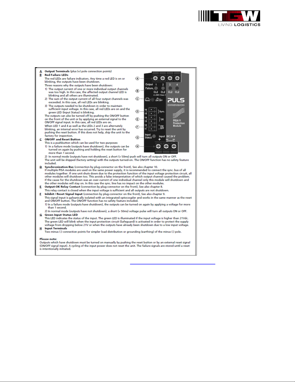
Status Indicators
The Class 2 protection module internal to each IntelliROL Combination power supply has status
indicators for the input and outputs. The Input Status indicator will be illuminated solid green
when the input voltage is above 21V. The input protection circuit will be activated if the input
voltage drops to 21V or less. If this occurs, the Input Status indicator will be flashing green.
The indicator will be off if there is no input voltage.
There are four Output Failure indicators, one for each Class 2 output circuit, on the Class 2
protection module. The status of the indicators is as follows:
•One is flashing red and the others are on solid red – excessive output current was
sensed on the output associated with the flashing indicator.
•All four are flashing red – the output current sum for all four outputs was excessive.
•All four are on solid red and the Input Status indication is flashing green – the input
voltage has dropped below 21V and the module is in input protection mode.
•All four are on solid red and the Input Status indication is on solid green – the outputs
have been turned off via the ON/OFF button or ON/OFF signal input.
•The indicators associated with outputs 1 and 4, as well as the indicators for outputs 2
and 3 are alternately flashing red – an error internal to the protection module has
occurred.
ON/OFF and Rest Button
The Class 2 protection module has one push button that serves two purposes. If the module is
faulted but the fault condition has been resolved, press and hold the ON/OFF – Reset button for
more than 1 second to reset the module. If this same button is pressed for more than 50
milliseconds, but less than 1 second, the Class 2 output circuit will switch from on to off or off to
on, depending upon their current state.
I/O Connector
An I/O connector is located on the front of the Class 2 protection module in every IntelliROL
Combination power supply. There are three functions controlled via this connector. First, the
ON/OFF – Reset function can be controller through terminals 11 and 12 of the connector. It
functions in the same manner as the push button. Second, the status of the protection module
can be monitored via the Output-OK relay. A set of dry contacts is available through terminals
P/N: 1176718 REV: 02/17/2021 Page 16 of 32
13 and 14. When the module is operating properly, the contacts will be closed. Third, multiple
modules can be synchronized using the Synchronization Bus through terminals 15 and 16. If a
module shuts down due to entering input protection mode, all synchronized modules will shut
down together.
For Puls Power Supply Information visit: http://www.pulspower.com/us/home/

P/N: 1176718 REV: 02/17/2021 Page 17 of 32
Chapter 7: CONNECTIONS
7.1: INTERNAL TO POWER SUPPLY
Incoming Power Circuits
All IntelliROL power supplies have a removable plate on the bottom of the enclosure. This plate
can be used as the entry point for cable, conduit, etc. by cutting holes in it for incoming and
outgoing power and signals. The incoming power connections are made at the line side of the
disconnect switch. There is also a ground lug for connecting the ground wire from the power
source. For power supplies that operate on 120VAC, a terminal block is provided for connection
of the neutral wire from the source of power.
Class 1 Circuits (Motorized Roller Power)
The outgoing power connections are made at the terminal strip inside the IntelliROL power
supply enclosure. Class 1 Circuit 1 is used to supply power to motorized rollers in an IntelliROL
conveyor. The power harness on the conveyor is made up of 10AWG brown and blue wires.
The brown wire should be connected to the terminal labeled 1121 on the terminal strip. The
blue wire should be connected to the terminal labeled 1102 to the right of the terminal labeled
1121 terminal on the terminal strip. A second Class 1 circuit is available at the terminal strip as
well. Class 1 Circuit 2 can also be used to supply power to motorized rollers that are separate
from Class 1 Circuit 1. The brown wire of the power harness for the second set of rollers should
be connected to the terminal labeled 1321 on the terminal strip. The blue wire should be
connected to the terminal labeled 1102 to the right of the terminal labeled 1321 on the terminal
strip. The power harness included with every IntelliROL power supply can be used to make
these connections. Be sure to follow all applicable codes governing the electrical installation of
your IntelliROL conveyor system.
Class 2 Circuit (CRUZcontrol Power)
The connections for the Class 2 Circuit found in each IntelliROL Combination power supply are
made at the terminal strip inside the IntelliROL power supply enclosure. A CRUZcontrol tee
cable is used to make the connection between an IntelliROL Combination power supply and a
CRUZcontrol system on an XP43 or NBC conveyor system. The tee cable contains four color-
coded wires; brown, blue, white and black. The black and white wires are not used when
connecting to the power supply. They should be separately insulated against contact with
anything else inside the power supply enclosure. The brown wire from the tee cable should be
connected to the terminal labeled 1201 on the terminal strip. The blue wire should be
connected to the terminal labeled 1102 to the right of the terminal labeled 1201 terminal on the
terminal strip.

P/N: 1176718 REV: 02/17/2021 Page 18 of 32
7.2: AT CONVEYOR EQUIPMENT
Class 1 Circuits (Motorized Roller Power)
The power harness included with each IntelliROL power supply has a connector at each end.
One connector is female and the other is male. The harness can be cut in the middle and used
to connect two Class 1 circuits to the power harnesses of two IntelliROL conveyor systems.
This should be done at the joint between two conveyor beds. Instead of connecting the power
harnesses from the two beds together, connect them to the two pieces of harness from the
power supply via the male and female connectors. The cut ends of the harness pieces should
be connected to the power supply terminal strip as described above. Be sure to follow all
applicable codes governing the electrical installation of your IntelliROL conveyor system.
Class 2 Circuit (CRUZcontrol Power)
A CRUZcontrol tee cable is used to connect an IntelliROL Combination power supply to a
CRUZcontrol system on an XP43 or NBC conveyor system. For an end-fed system, either the
male or female connector on the tee cable is connected the compatible connector on the end of
the CRUZcontrol interconnection cable. For a center-fed system, both connectors of the tee
cable are used to connect to the interconnect cables of two adjacent CRUZcontrol devices.
Simply disconnect the two interconnect cables and connect them to the tee cable. For more
information, refer to the TGW IOM manual for your CRUZcontrol product.

P/N: 1176718 REV: 02/17/2021 Page 19 of 32
Chapter 8: APPLICATION
Number of Rollers per Power Supply
The number of motorized rollers used on each Class 1 circuit is a very important aspect of
applying an IntelliROL power supply to a conveyor system. The answer depends upon several
characteristics of each specific application, such as conveyor speed, product weight,
transportation conveyor versus accumulation conveyor, singulated versus slug release, etc. As
a general rule of thumb, a 10A circuit can supply power for up to three motorized rollers, while
each 20A circuit can power up to nine motorized rollers. This means a power supply rated for
40A output can provide power for up to 18 motorized rollers. A unit rated for 80A can feed up to
36 motorized rollers. Make sure the 36 rollers are evenly distributed amongst the four 20A
circuits. No more than nine motorized rollers per 20A circuit. Keep in mind the first 20A circuit
in a combination power supply also supplies power for the Class 2 circuit feeding CRUZcontrol.
This will reduce the motorized roller count on that first 20A circuit by at least one. The amount
of current diverted from the first 20A circuit to the Class 2 circuit depends upon the number of
zones of CRUZcontrol being powered by the Class 2 circuit. Please refer to the TGW
application guidelines for your specific equipment.

P/N: 1176718 REV: 02/17/2021 Page 20 of 32
Chapter 9: STATUS INDICATORS
Standard Power Supplies
The table below lists the expected state of each indicator for all IntelliROL Standard power
supplies when they are powered and in normal operation. These indicators can be found on the
power supply unit internal to the power supply enclosure. Refer to Table 2: IntelliROL Standard
Power Supply Status Indicators.
Indicator
Expected State
Diagnostic Relay
Contact Closed
DC OK
Solid Green
Table 2: IntelliROL Standard Power Supply Status Indicators
Combination Power Supplies
The table below lists the expected state of each indicator for all IntelliROL Combination power
supplies when they are powered and in normal operation. These indicators can be found on the
Class 2 protection module internal to the power supply enclosure. Refer to Table 3: IntelliROL
Combination Power Supply Status Indicators.
Indicator
Expected State
Output-OK Relay
Contact Closed
CL2 Output 1
Off
CL2 Output 2
Off
CL2 Output 3
Off
CL2 Output 4
Off
Table 3: IntelliROL Combination Power Supply Status Indicators
This manual suits for next models
51
Table of contents


