Thales VesseLINK VF350BM User manual
i
Installation Guide 84464 Rev. 2
DECEMBER 2017
JUNE 2017
JUNE 2017
JUNE 2017
COPYRIGHT © 2017
THALES DEFENSE & SECURITY, INC.
ALL RIGHTS RESERVED
This document contains technology controlled for export by the U.S. Department of
Commerce in accordance with Export Administration Regulations. Diversion contrary to
U.S. law prohibited.
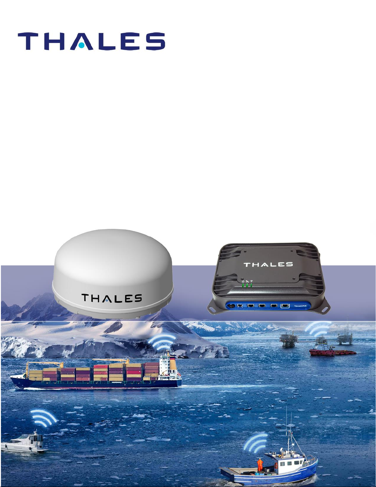
VesseLINK
Installation Guide
ii
Installation Guide 84464 Rev. 2
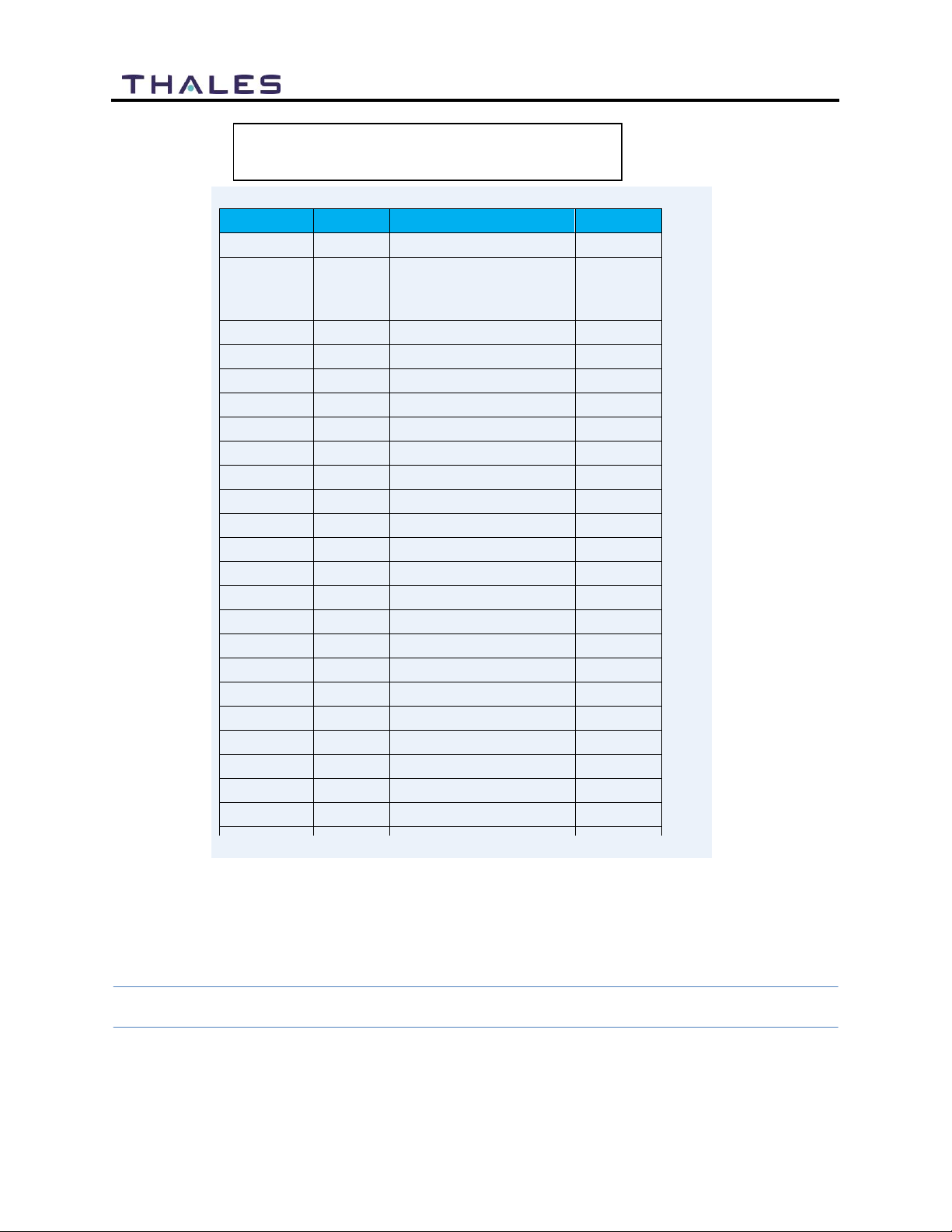
Date
Revision
Description
Author
Nov 2017
1
Initial release
DCrossen
Dec 2017
2
Update –incorporation
of comments; added
Quick Start Guide
SJacques
WARNING –INFORMATION SUBJECT TO EXPORT CONTROL RESTRICTIONS
This document contains technology controlled for export by the U.S. Department of
Commerce in accordance with Export Administration Regulations (EAR). Diversion contrary
to U.S. law prohibited. Include this notice with any reproduced portion of this document.
Revision History
iii
Installation Guide 84464 Rev. 2
Export Compliance:
This product is controlled by the export laws and regulations of the United States
of America. The U.S. Government may restrict the export or re-export of this
product to certain individuals and/or destinations. For further information, contact
the U.S. Department of Commerce, Bureau of Industry and Security.
This product User shall comply with all applicable
laws related to export and
import of this product
in any jurisdiction and/or
government authority.
User
shall be responsible for complying with any and all export and import restrictions,
laws and regulations in any country User is conducting business.
Disclaimer:
This manual contains information that is current as of the date shown on the front
cover. Every effort has been made to ensure the correctness and completeness of
the material in this document. The information in this document is subject to
change without notice.
Thales® and any other Thales trademark or Thales service mark referred to or
displayed in this document are trademarks or registered trademarks of Thales.
Legal Notices
This product is subject to a Limited Warranty, Limitations, Exclusions, and Terms
and Conditions, which can be found on line at www.thalesdsi.com.
Prior to Installing this product, read and understand this Installation Guide and the
User Manual, including the safety warnings and information. Failure to do so could
result in serious injury or death.
Intellectual Property
User acknowledges that the Products
involve
valuable patent, copyright,
trademark, trade secret and other proprietary rights
of
Thales and others. No
title to or ownership of any proprietary rights related to any Product is
transferred
to
User or any Customer pursuant to the use of this product. The
purchase of any Thales products shall not be deemed to grant either

iv
Installation Guide 84464 Rev. 2
directly or by implication or otherwise, any license under copyrights,
patents, or patent applications of Thales or any third party software
providers, except for the normal, nonexclusive, royalty free license
to use that arises by operation of law in the sale of a product.
Content Copyright
User is exclusively responsible for the use of this product, including
proper use of third party copyrighted materials. If the User violates
these terms, the User agrees to defend, indemnify and hold Thales
harmless with respect to any claims or actions by third parties
related to the improper use of copyrighted material and to pay all
costs, damages, fines and other amounts incurred by Thales, or on
its behalf, in the defense of any such claims or actions.
Indemnity
User agrees to defend, indemnify and hold Thal es harmless with
respect to any claims or actions by any governmental entities or
other third parties related to any violation of law with use of the
Product or Accessories, misuse of the Product or Accessories under
these Terms and Conditions, or any othe r violation of these Terms
and Conditions and further agrees to pay all costs, damages, fines
and other amounts incurred by Thales, or on Thales’s behalf, in the
defense of any such claims or actions.
SOFTWARE LICENSE
The following terms govern User’s a ccess and use of the Thales -
supplied software (“Software”) contained on the Product or
Accessories.
License. Conditioned upon compliance with these Terms and
Conditions, Thales grants to USER a nonexclusive and
nontransferable license to use for USER’s in ternal purposes the
Software and the Documentation. “Documentation” means any
v
Installation Guide 84464 Rev. 2
written information pertaining to the Software and made available
by Thales with the Software in any manner. USER shall use the
Software solely as embedded for operation of this product.
No other licenses are granted by implication, estoppel or otherwise.
Thales Product Warranty Claim Process
Please see the Thales website at www.thalesdsi.com.
Table of contents
Other Thales Marine GPS System manuals

Popular Marine GPS System manuals by other brands

Airmar Technology Corporation
Airmar Technology Corporation GH2183 Owner's guide and installation instructions

JRC
JRC JHS-183 installation manual

Thuraya
Thuraya IP Voyager user guide

Furuno
Furuno GP-1610CF Operator's manual

Raytheon
Raytheon NautoPilot NP 5100 Operator's manual

Furuno
Furuno GP-1650WDF Operator's manual


Raymarine
Raymarine G-Series system Installation & commissioning instructions

Radio Zeeland DMP
Radio Zeeland DMP Sigma 120 manual

Addvalue Innovation
Addvalue Innovation wideye SABRE RANGER 5000 quick start guide

Garmin
Garmin GPSMAP 190-01120-00 owner's manual

Humminbird
Humminbird 532162-1_B installation guide

Garmin
Garmin GWS 10 Marine Wind Sensor Declaration of conformity