The Harvestman Stillson Hammer mkII User manual
1
QUICK START
Basic patch: Connect the CV OUT 1 to the 1V/
Oct input of a VCO module. Patch this module into a VCA,
whose volume is controlled by an envelope generator.
Patch the GATE OUT 1 to this envelope generator’s
trigger/gate input. Repeat with additional outputs and
external oscillators/VCAs, or use the additional CV outs to
modulate other parameters of your instrument.
We recommend the use of INDUSTRIAL
MUSIC ELECTRONICS modules such as the HERTZ
DONUT, PISTON HONDA, and DOUBLE ANDORE with
the STILLSON HAMMER. The MKII versions of these
modules are specially designed to work the best with this
sequencer. If you turn the large frequency knobs on either
of these oscillator modules to the zero position while the
1v/OCT signal is patched to the sequencer, the basic pitch
will correspond to the note and scale names shown on
the STILLSON HAMMER’s display. If you are using other
models of oscillator, take care to adjust them so that all
oscillators connected to the sequencer are playing in tune
if given the same output voltage. Push the RUN/STOP
button so it turns green and the sequence starts playing.
Next, select Track 1 by pressing its TRACK
SELECT button. Next, push the GATE PAGE SELECT
button and move some sliders so that the LEDs light up.
The attached VCA and envelope should be
triggering and emitting sound Next, push the CV PAGE
SELECT button and move the sliders to set the pitches
for each of your gated steps. See the TRACK OPTIONS
text below for help in setting up your quantizer scale.
The 16 sliders at the bottom of the module are used for
programming all sequence data. Their function will change
depending on the PAGE SELECTION. If the page focus is
changed, the sliders will not program new data into the
sequence unless they are moved slightly from their current
physical positions.
TRANSPORT CONTROLS:
Press the RUN/STOP button to start or stop the
sequence. When running, it will advance at a rate set by
the CLOCK controls. Even if the clock source is external,
the sequencer will not run unless the mode is set to RUN
(the button will light green if running, and red if stopped.)
The jack above this button accepts external trigger signals
and has the same eect as the button.
While the sequencer is stopped, you can change
the active step position by turning the ROTARY ENCODER.
The ENCODER also has a built-in button. If you push
down on the ROTARY ENCODER while the sequencer is
stopped, it will activate all four GATE OUTS. When you
change the step by using the encoder, the display will
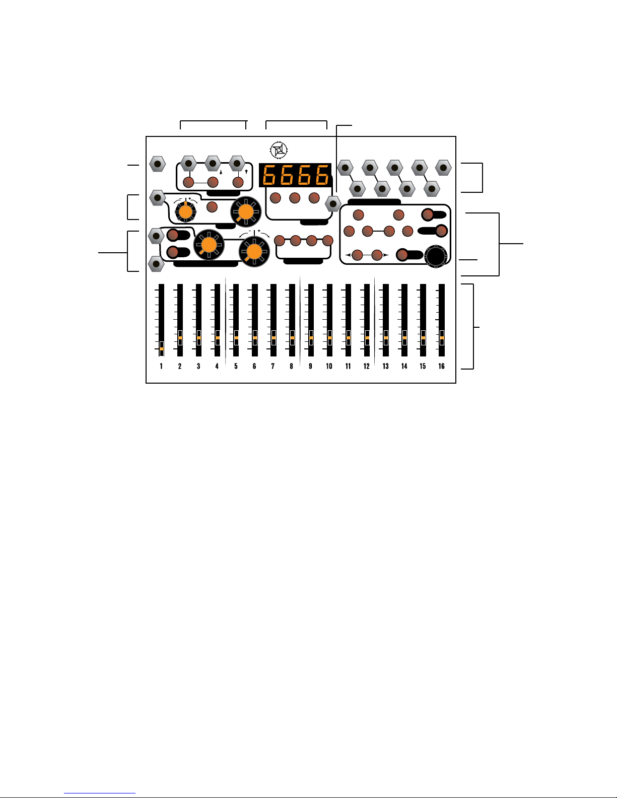
COPY/
PASTE
CLOCK
LOAD/
COMPARE SAVE
TRANSPORT
ASSIGNABLE CONTROLLERS TRACK SELECT
CV
RANGE
COUNT
BURST
SPEED
INIT
GATE
SLIDED ELAY
RANDOM
SHIFT
PAGE SELECT
MEMORY
4-CHANNEL PERFORMANCE SEQUENCER
STILLSON HAMMER
INDUSTRIAL MUSIC ELECTRONICS MODEL 1974 MARK II • MANUFACTURED IN PORTLAND, OREGON • INSPECTED IN SEATTLE, WASHINGTON USA
TRANSPORT
EXT
CLK
CVIN
CV
IN
CVOUTS
GATE
OUTS
CLK OUT
RUN/
STOP
MODE
A
B
RESET
IVIIIIII
IVIIIIII
RUN/
STOP
A
B
RESET
TRANSPORT CONTROLS
(page 1, 4)
DISPLAY
MEMORY BUTTONS (page 5)
EXTERNAL RECORD TRIGGER IN (page 5)
CV OUTS
CLK OUT
GATE OUTS
(page 1)
ENCODER
PAGE SELECT
MODIFIERS
(page 3-4)
SLIDERS
EXT CLK IN
CLOCK
OPTIONS
(page 2-3)
ASSIGNABLE
CV A/B
(page 3-4)
INDUSTRIAL MUSIC ELECTRONICS
STILLSON HAMMER MARK II
OPERATIONS MANUAL OS v. 1.0

2
show the value of the currently active step, programmed
onto the appropriate parameter page. You may move the
associated slider to program a new value at this time,
using the display to set a precise value.
By pushing the RESET button, you will can use
a trigger event to be red from the middle jack. You can
use this to reset other sequencers synchronized to the
Stillson Hammer. The rightmost jack accepts a trigger
signal that acts the same as the button. When a RESET
event is received, the sequencer will reset all tracks to
Step 1 when the next clock event is received. This is
useful for synchronized playback with other instruments or
sequencers, and also to internally align the four tracks if
you are using multiple track lengths or clock divisions.
TRACK SELECT:
These buttons correspond to the four CV/GATE
tracks. When pressed, the track will be selected and
the button will turn red (or orange if the track is muted.)
Unselected (but active) tracks are colored green. Muted
tracks that are not selected will not be lit. To mute or
unmute a track, hold down SHIFT and press a TRACK
SELECT button. Pressing the TRACK SELECT button
twice in a row will open the TRACK OPTIONS page on the
display (see below.)
CLOCK OPTIONS:
By pressing the button in the CLOCK section, you
can switch between Internal or External clock. The display
will show ICLO or ECLO, and the button will turn green
(internal) or red (external) to show your selection.
The Internal clock will run at a speed set by the
combination of the large manual control knob, and the
nearby CV input and attenuverter. The manual knob can
set the tempo from approximately 30-300 BPM, with more
range available through the use of the Clock CV input. If
you are performing in Internal clock mode and want to
avoid mistaken changes of tempo, hold down SHIFT and
press the CLOCK button to turn o the large knob. The
display will briey read COFF and the button will not light
up. Repeat to turn it back on.
In External clock mode, patch a gate or
trigger signal into the EXT CLK jack in the corner. The
sequence will not run without clock pulses coming in. We
recommend a straight, square clock signal as new steps
will be clocked in on the rising edge of the signal.
The CLK OUT jack in the opposite corner will emit
a copy of the selected clock signal if the sequencer is
running. It will be unaected by any clock divider settings.
Use this with the RESET signal to synchronize external
equipment to the Stillson Hammer.
PAGE DESCRIPTIONS:
CV:
When selected, the sliders will edit the CV value
of the step that will come out of the associated track’s
output. If the quantizer is enabled (see TRACK OPTIONS),
the value displayed will consist of the note number and the
octave. If the quantizer is o, the value will be displayed
in volts. Use the two RANGE buttons below to select the
octave range that the slider will represent. The range in
volts will be briey shown on the display.
For ease of editing, press the encoder button to
reveal which steps have active gates on the slider LEDs.
SLIDE:
Use the sliders to select the time it will take for
a given step’s CV value to transition to the next one.
INITializing this page will reset all values to zero. The slide
times are proportional to the tempo setting. The slide has
a linear slope.
For ease of editing, press the encoder button to
reveal which steps have active GATEs on the slider LEDs.
GATE:
When selected, the slider LEDs will light if an
active GATE is programmed onto that step.
If the slider is pushed to its lowest position, the
GATE will be turned o. The LENGTH of the GATE event is
determined by the position of the slider, represented as a
division of the length of one step. If the slider is set to the
bottom position, the GATE will be disabled for that step. If
the slider is set to the maximum position, it will cause the
GATE output to re for the maximum length, and TIE to the
next GATE without retriggering.
When BURST is active, this page also controls the
GATE length of the repeat burst events.
For ease of editing, press the encoder button to
reveal which steps have active BURSTs on the slider
LEDs.

3
BURST- COUNT:
Select this page for the current track by pressing
the “COUNT” page select key. When selected, the slider
LEDs will light if an active BURST trigger is programmed
onto that step. Note that bursts will not repeat unless you
have programmed a value into the “SPEED” page.
The BURST function causes the GATE OUTPUT
for a track to repeat itself when its step is triggered, also
known as “retriggering” or “ratcheting". You can choose
the amount of repetitions, as well as enable the BURST
from this page.
To assign a BURST to a step, move the slider
upwards. If a slider is at the bottom of its travel, the
BURST for that step will be inactive. Watch the display
to see the exact number of repeat events that you are
programming.
For ease of editing, press the encoder button to
reveal which steps have active GATEs on the slider LEDs.
BURST - SPEED:
This page controls the delay before a BURST
event repeats. If you program this page, its data will only
be useful for steps with active GATE and BURST. The
speed setting will not be updated if a BURST is currently
running. You must activate a new BURST from the COUNT
page to change the repeat rate.
For ease of editing, press the encoder button to
reveal which steps have active BURST triggers on the
slider LEDs.
DELAY:
Use the sliders to program the time oset for each
step’s GATE. This is expressed as a division of one step
length. A slider set to the minimum position will give no
DELAY to the GATE. If the delayed GATE event overruns
the step’s length, it will be reset at the end of the step
unless the corresponding GATE length on the original step
is set to Tie.
For ease of editing, press the encoder button to
reveal which steps have active GATEs on the slider LEDs.
MODIFIER BUTTONS:
INIT
The INIT key initializes sequence parameters. You
must hold it down while pushing other buttons. You may
do this with any of the PAGE SELECT keys, or you may
initialize entire tracks by holding it down and pressing any
of the TRACK SELECT keys.
SHIFT
The SHIFT key adds alternate functionality to other
buttons or sliders.
Hold SHIFT and press the CLOCK button to
disable the operation of the large clock rate knob, for live
performance convenience.
Hold SHIFT + ENCODER buttons while pressing
a RANGE key to increment or decrement the currently
playing preset. Unless in Random transport mode, the
preset will change when the sequence reaches Track 1’s
reset point.
Hold SHIFT + ENCODER buttons while moving
a slider on any page to set all steps on that page to that
slider value, as if you were moving all 16 of them at once.
RANDOM
Hold RANDOM and press any PAGE key to
randomize its slider values. The same can be done with a
TRACK SELECT button to randomize an entire TRACK’s
basic parameters. When RANDOMizing a track, hold down
the SHIFT key as well, to cause a deeper randomization
across all pages (including CV destinations)
Hold RANDOM and press the LOAD key to load a
random sequence from the MEMORY.
CV A/B - ASSIGNABLE CONTROLLERS
The two external A/B inputs combine with the
action of the large manual controls to modify selected
parameters of the sequence. The Stillson Hammer expects
voltages in the range of 0 to +5V. Voltages outside of this
range should not damage the unit, but will have no eect
on the sequence.
The two external A/B channels must be
programmed by holding down either of the two buttons.
While holding down the buttons, move the sliders to
program the value for each step. Think of the sliders in
this mode as “attenuators per step”, where the incoming
CV (or manual control value) will be multiplied by the slider
value before being sent out to the selected destinations.
Each track can have very dierent CV programs all sharing
the same two control sources, so a single preset can
provide hours of performance variation if appropriately

4
programmed.
To assign the controller to a destination, hold down
CV A or B, and press a PAGE button so the destination
button lights up green.
The manual control on CV channel B is bipolar:
the center position is zero, turning it counterclockwise
subtracts from the page's programmed value, and turning
it clockwise adds to the value.
TRACK OPTIONS:
Press a TRACK select key twice. The page select
LEDs will turn o and the display will change. Use the
ENCODER button or the three keys immediately below the
display to select the editing target.
TRACK LENGTH
The leftmost button (and two digits) show the step
length of the sequence. When the button is illuminated
green, you can use the rotary encoder to set the length
from 2 to 16 steps. Dierent tracks can have dierent
lengths, so you can use the RESET button to set the
sequence position of all tracks to step 1 when they get
misaligned.
QUANTIZER ROOT:
The third digit in the display shows the scale root.
When the middle button below the display is illuminated
green, you can use the rotary encoder to change the root
of the track’s scale. If the display reads “—“ on the right
side, the quantizer is disabled. If it says “12”, it’s 12-tone
quantized. Otherwise, the letter shows the root of the
scale, with the “.” meaning “sharp”. Changing the root
note in this mode will cause a post-quantizer shift of the
absolute position of the slider, so you can change the
“key” of the sequence by modifying the root.
QUANTIZER SCALE TYPE:
The last digit in the display shows the scale type.
When the rightmost button below the display is illuminated
green, you can use the rotary encoder to change the root
of the track’s scale. Setting the type to “—“ or “12” will
override the root selection.
SCALE TYPES REFERENCE:
Quantizer o --
All Semitones 12
Major |-|
Minor |-|.
Dorian d
Lydian L
Phrygian P
Mixolydian Y
Locrian l
Fifths and Octaves 5
Major Triad 3
Minor Triad 3.
Major 6th 6
Minor 6th 6.
Major 7th 7
Minor 7th 7.
TRANSPORT OPTIONS:
Press the middle key in the “TRANSPORT” control
section to enter the TRANSPORT OPTIONS menu. The
page select LEDs will turn o, and the display will change.
Press the encoder button (or the buttons immediately
below the display) to select the parameter to edit. To exit
this mode, press any page select key.
CLOCK DIVISOR:
The leftmost button (and leftmost two digits) in
the display show the clock divisor for the track. You can
divide the incoming clock by 1-32. Use the rotary encoder
while selected to change this parameter. We recommend
leaving Track 1’s divider at 1, since the preset changes are
decided when Track 1 resets, and longer clock divisions
could cause a long delay before the commanded preset is
nally loaded.
TRANSPORT MODE:
The rightmost button (and rightmost two digits) in
the display show the transport mode.
Fd: FORWARD MODE: A track will start at step 1 and
proceed to the maximum step set as the TRACK LENGTH.
When this happens, it will reset to 1.
Pd: PENDULUM MODE: A track will start at step 1 and
proceed to the maximum step set as the TRACK LENGTH.
When this happens, the sequencer will start to run
backwards to step 1, and repeat.
Rd: RANDOM MODE: A random step will be selected
when the divided clock arrives at the track.

5
CONNECTING TO OTHER SEQUENCERS:
For best results when using one clock source or
sequencer to control multiple Stillson Hammers (or other
sequencers), use a Multiple module or stackable patch
cables to send the master clock and reset signals to all
connected sequencers. Don’t “daisy chain” the clock
signals.
COPY/PASTE
To copy a page of data to the copy buer, hold
down the COPY/PASTE button and push a PAGE SELECT
button. The COPY/PASTE button should light up red. To
paste this data, select your destination track and page,
hold down the COPY/PASTE button, and push your
desired destination's PAGE SELECT button. You can also
copy entire tracks by holding COPY/PASTE and pressing a
TRACK SELECT button.
MEMORY - PRESET STORAGE
The Stillson Hammer MkII can store 32 preset
sequences in nonvolatile memory.
Press the LOAD button to show the intended load
source. You can change this by turning the rotary encoder.
To cancel out of this selection, press the ENCODER
button. Otherwise, press the LOAD button again to load
the selected sequence when Track 1 resets. You can
also command LOAD operations by holding down the
RANDOM button before pressing LOAD, or by SHIFT
+ ENCODER + RANGE to increment/decrement the
sequence.
Press the SAVE button to show the intended
SAVE destination. You can change this by turning the
rotary encoder. To cancel out of this selection, press the
ENCODER button. Otherwise, press the SAVE button again
to save the selected sequence.
EXTERNAL RECORD TRIGGER:
A gate signal arriving at this jack will cause the
voltage preset at the CV B jack to be recorded into the
current step on the CV page of the currently selected
track. This jack accepts voltages from 0-5V, so select
the CV range “0-5V” if you would like the track’s output
to resemble the voltage input. Otherwise, the 0-5V input
range will be mapped to the slider range set by the
RANGE buttons on the track. Note that this CV input is
not calibrated, so do not expect precise tuned voltage
operation in this mode. Experiment with dierent quantizer,
CV voltage shift, and clock division/track length settings
for each track, so that the single input voltage and
record trigger can dramatically alter dierent parts of the
sequence as each track is selected.
TEST MODE/CALIBRATION
USE CAUTION WHILE IN TEST MODE. YOU CAN
ACCIDENTALLY ERASE ALL OF YOUR SEQUENCES IF
YOU PUSH THE TRACK 4 KEY.
To access TEST MODE, hold down the LOAD
button while turning your modular system’s power on. All
the buttons should light up red, and they will turn green
if you press the GATE page button. Measure the voltage
coming out of any of the CV output jacks with a voltmeter.
If it does not equal 8 volts, turn the trimpot on the back of
the module until it does.
To safely exit TEST MODE, press the TRACK 1 button. To
erase the entire sequence memory, press the TRACK 4
button.
SEQUENCE STORAGE CHIP
The storage chip is a Microchip 25LC512 in DIP
package. It stores 32 sequences. You can replace it with
a new chip, and back up the data to computer by using
the Industrial Music Electronics model 1991X-2 ROM
programmer board and a Microchip PicKit2. Do not insert
or remove the chip while the module is powered up.
When you are installing a new, blank chip into
the socket, you MUST enter TEST MODE and perform
the ERASE command, or the sequencer will not operate
correctly.
MORE INFORMATION:
http://www.industrialmusicelectronics.com/
modules/stillson/
Find this document, rmware updates, media
les, and additional information here.
SUPPORT:
Write to this address if you need more help.
Table of contents


