Theben DIMAX 534 plus User manual

1
DIMAX 534 plus
5340001
307171 02
Universal dimmer
EN
1. Basic safety information
Danger of death through electric shock or fire!
¾ Installation should only be carried out by a
qualied electrician!
WARNING
LDue to increasing technical progress, conspicuous features
in dimming behaviour or malfunctions cannot be ruled out
for dimmed lamps (in particular LEDs)
•The dimmer is designed for installation on DIN top hat
rails (in accordance with EN 60715)
•It conforms with IEC/EN 60669-2-1 if correctly installed
2. Proper use
•The dimmer switches and dims the brightness of diffe-
rent lamps such as bulbs, high-voltage halogen lamps,
low-voltage halogen lamps (conventional or with elect-
ronic transformer), dimmable compact uorescent lamps
(energy saving lamps) or dimmable lamps for 230 V as
well as for fans
•The setting for brightness is carried out using the
dimmer on the button connected
•The universal dimmer has a lamp-friendly "soft" on and
off system, automatic detection of the load type (not
in the case of ESL2 and LED2), overheating protection
against overload as well as a short-circuit protection.
•For use in private and public buildings, in closed rooms
Disposal
Dispose of device in environmentally sound manner
3. Installation and connection
Mounting the dimmer
Danger of death through electric shock or fire!
¾ Installation should only be carried out by a
qualied electrician!
WARNING
Disconnect power source
Ensure device cannot be switched on
Check absence of voltage
Earth and bypass
Cover or shield any adjacent live components
Mount the dimmer in the lower part of the distributor to
avoid an excessively high temperature during use.
In the case of a service line of >300 W keep an 8 mm dis-
tance to the right and left of the device.
Connecting the dimmer
¾ Always operate electrical and conventional transformers
with the minimum load specied by the manufacturer.
¾ Use only dimmable compact uorescent lamps / LED lamps
as normal compact uorescent lamps / LED lamps may be
destroyed.
¾ When changing the lamps, switch off the power supply
(at the fuse box) so that the automatic load detection is
reactivated.
¾ Do not connect dimmer load connections (L´) in parallel.
¾ Do not by-pass or short-circuit the dimmer.
¾ Do not install any isolating or variable transformers before
the dimmer.
¾ Do not mix wound and electronic transformers in the
installation.
¾ Do not install wound transformers and compact uorescent
lamps /LED lamps mixed.
¾ Do not connect push button with glow lamp.
¾ Correct, automatic load detection is only possible with a
connected load.
¾ Only use transformers approved by the manufacturer for
dimmer operation.
Connection with 8 ... 230 V
Push buttons A1/A2 On/Off/Dim
LS 1 = Lighting scenario 1
LS 2 = Lighting scenario 2
LS 3 = Lighting scenario 3
9070825
N
L
N
L
A2A1
B1
–
+
AC/DC
8 ... 230 V
L‘
T
LS 1LS 2LS 3
Use compensation module 9070825 to prevent the LEDs
from afterglow or ickering.
Install the compensation module parallel to the
consumer.
!Component can get hot!

2
Connection with 230 V
N
L
L´
N
L
A2A1
B1
LS 1 LS 2 LS 3
Connection with Booster DMB 1 T (4930279)
DMB 1 T
N
L
L´
N
L
L´
N
L
A2A1
B1
LS 1 LS 2 LS 3
q
q
Performance upgrade (see technical data for DMB 1 T
booster)
4. Description of functions
The dimmer is equipped with a rotary switch with 10 posi-
tions in order to set the operating mode:
Rotary switch for setting 10 func-
tions
Potentiometer for setting the dim-
ming time from 1 s to 60 min (for
wake-up and snooze function, stair-
case time switch and switch function)
ON = Dimmer is always on
Functions for dimmable compact uorescent
lamp (CFL) (ESL)
Position 1
With automatic load detection (usually trailing edge),
•always start with 100% to ignite the CFL
•Dimming down only possible after 3 sec.
Position 2
No automatic load detection (always with leading edge)
•Always start with at least 50% to ignite the CFL
•Dimming down only possible after 2 sec.
Position 3 Prog
Teach in light settings and minimum brightness (only for CFL)
LWith several compact uorescent lamps, an annoying
ickering may occur when dimming in position 1.
In this case, use position 2.
Carry out settings only with warm compact uorescent
lamps (after approx. 5 minutes).
LSeveral compact uorescent lamps may cause an overload
in position 2 that automatically leads to the load dimming.
Select position 1 in order to avoid this
Function for LEDs
Position 4: LED 2
No automatic load detection (always with leading edge) (ideal
for dimming problems with LEDs)
LSeveral LED types may cause an overload in position 4
that automatically leads to the load dimming.
Select position 6 or 7 in order to avoid this
DIMAX 532
A1 A2
N
LL´
perm
ON
2
1
Minimum
LED1
Functions for standard lamps (e.g., bulbs, halogen
lamps, transformer, LEDs)
Position 5 Prog
Teach in light settings and minimum brightness
Position 6 Comf
Comfort function
With automatic load detection for the conventional lamp
types
Position 7 Strd
Standard function
With automatic load detection for the conventional lamp
types
Position 8
2-push button function using diode module with double
switch or rocker button
Position 9
Staircase time switch function
Position 10
Switch function (e.g., for presence and motion detector)
5. Setting the functions
1. Wake-up function (comfort function)
•active in position 1, 2, 4, 6, 10
The dimmer dims from the minimum brightness up to the
switch-on brightness taught-in within the set dimming time
(activation via double click).

3
2. Snooze function (comfort function)
•active in position 1, 2, 4, 6, 10
The dimmer dims from the current dimming value up to the
minimum brightness within the set dimming time and swit-
ches off (activation via double click).
3. Dimming switch-on function
•applies for position 1, 2, 4, 6, 7, 8, 10
The dimmer switches on with minimum brightness and dims
until one releases the button again, or the maximum bright-
ness has been reached (activation by pressing the button for
longer, > 1 s).
4. Switch-on brightness
•applies for position 1, 2, 4, 6, 7, 8, 10
•Switch-on brightness can be set (presetting 100%) (acti-
vation by pressing the button, < 1 s)
Teach in switch-on brightness
Set the desired switch-on brightness via the button at input
A1/A2 in position 1 (or 2, 4, 6, 7, 8, 10 ).
Keep the button pressed (> 10 seconds) until the teach in
is conrmed by a change in the brightness. Afterwards it is
set to the saved switch-on brightness.
5. Minimum brightness
•applies for position 3, 5
Teach in the minimum brightness
The pre-set minimum brightness is set in such a manner that
most lamps still light up.
Move the rotary switch to 5 (to 3 for compact uorescent
lamps). The current minimum brightness is approached.
Press the button at Input A1/A2 and dim up or down until
the desired minimum brightness value is reached.
Let go of the button; the brightness value is taken over.
Set the rotary switch back to the desired function.
▻Reason: if a certain brightness value is exceeded, cer-
tain compact uorescent lamps / LEDs go out and no
longer ignite.
Carry out settings only with warm compact uorescent
lamps (e.g., switch on for approx. 5 minutes).
6. 2-push button function using diode module
with double switch or rocker switch
•input B1 = push button input
•with switch-on brightness
•with dimming switch-on function
•ON button: switch on /dim up
OFF button: switch off /dim down
Diodenmodul
L
B1
AUS
EIN
Diode module 9070367
ON
OFF
7. Staircase time switch function
Setting the time with potentiometer (1 s – 60 min)
•Switch-off pre-warning: after expiry of the set time rapid
dimming down to 50% of the switch-in value. After 10 s,
slow dimming down to minimum brightness within 30 s.
•Long time function 60 mins: activation by pressing the
button for longer (conrmed by change in brightness)
LPressing the button again during the expiry time restarts
the expiry time (resettable, cannot be prematurely swit-
ched off).
30 s
10 s
1 s– 60 min
p
u
Zeit
Helligkeit
Brightness
Time
8. Switch function (e.g., for presence and motion
detector)
•At Input B1: not dened as push button but as switch
•Use of the diode module possible, up to 3 light settings
can be selected
•ON switch: slow dimming up; time can be set at potenti-
ometer 2; setpoint value set with function 5
OFF switch: slow dimming down; time can be set at
potentiometer 2 to minimum brightness, afterwards
switch off
p
p
Zeit
Helligkeit
100 %
x %
min
B1
A1/A2
0 %
langer Tastendruck
Brightness
Time
Long button push
Switch Switch
•At button A1/A2
– with switch-on brightness (preset 100 %)
– with dimming switch-on function
– with wake-up and snooze function
6. Operation
Light is OFF (with button: input A1/A2)
1 x short button
press
< 1 s Switch-on brightness
The dimmer starts with the switch-on bright-
ness taught-in (ex-factory 100 %)
1 x long button
press
> 1 s Dimming switch-on function
The dimmer switches on with minimum
brightness and dims until one releases the
button again, or the maximum brightness has
been reached.
2 x short button
press
Wake-up function
The dimmer switches on with minimum
brightness, then it is dimmed up using the
set dimming time (potentiometer ) until the
taught-in switch-on brightness.
4
Light is ON (with button: input A1/A2)
1 x short button
press
< 1 s Switch off
1 x long button
press
> 1 s Dimmer dims up or down
Dimming stops at minimum or maximum
value.
The dimming direction is changed by pressing
the button again.
1 x long button
press
> 10 s Dimmer dims to minimum or maximum value.
If the button is pressed for > 10 seconds, the
previous dimming value (start value) is saved
as switch-on brightness (conrmed by the
brightness changing). Then it is changed to
the saved switch-on brightness.
2 x short button
press
Snooze function
Dimmer dims within the set dimming time
(potentiometer ) to the minimum brightness
and switches off.
Lighting scenarios
Connection with diode module
Diodenmodul
B1
LS1
LS2
LS3
L
Lichtszene 1
voreingestellt 50 %
Lichtszene 2
voreingestellt 25 %
Lichtszene 3
voreingestellt 75 %
LS = Lighting scenario
Up to 3 lighting scenarios can be selected using the push
button at input B1. The enclosed diode module (9070367) is
required for this purpose.
Activating the lighting scenario
Briey press push button at B1. The pre-set value is started
up.
Teach in the lighting scenarios using functions 1, 4, 2, 6, 7
Set brightness value using button at A1/A2.
Press button B1 (for light setting LS1, LS2, LS3) for longer
than 10 s; the value is saved as lighting scenario (conr-
med by the difference in brightness). Following this, adjust-
ments are made according to the saved brightness.
Teach in lighting scenario with switch B1 at function 10
Set rotary switch to 5. The current minimum brightness is
approached.
Switch on switch at B1 (close); the lighting scenario is
approached.
Press button at Input A1/A2 to dim up or down.
Release button at Input A1/A2 at desired value; the value
is changed and applied for the activated lighting scenario.
Switch off switch B1 (open).
Set rotary switch to function 10 again.
Several light setting with diode module
Connection with diode module to a dimmer
Diodenmodul
B1
LS1
LS2
LS3
L
Lichtszene 1
voreingestellt 50 %
Lichtszene 2
voreingestellt 25 %
Lichtszene 3
voreingestellt 75 %
Diode module 9070367
Lighting scenario 1
preset 50
Lighting scenario 2
preset 25%
Lighting scenario 3
preset 75
Lighting scenario 1 can also be activated if buttons LS2 and
LS3 are pressed simultaneously. This makes it possible to save
using button LS1.
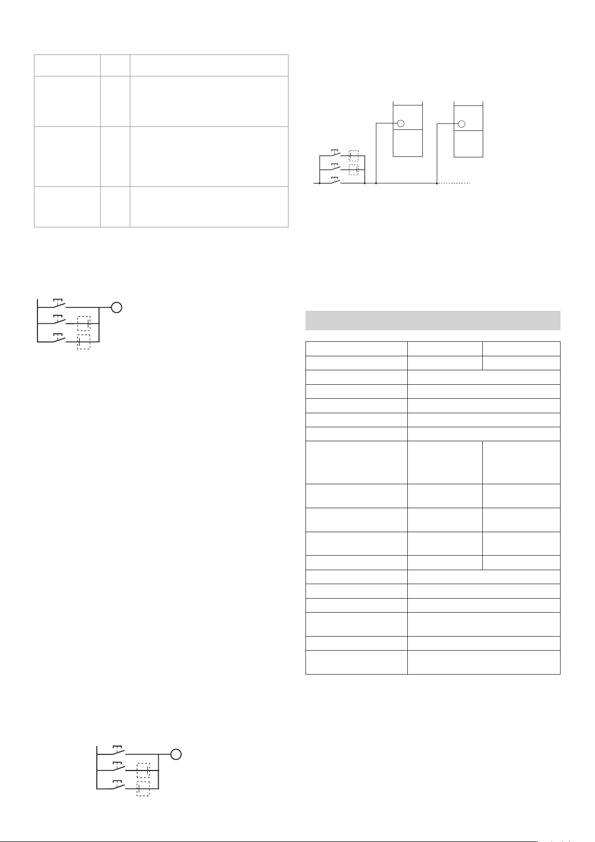
Connection with diode module to several dimmers
B1 B1
L
Examples
Central OFF: teach in all dimmers 0 %.
Central ON: teach in all dimmers 100 %.
Lighting scenario 1: teach in dimmer 1 20 %,
teach in dimmer 2 70 %, ...
Lighting scenario 2: teach in dimmer 1 50 %,
teach in dimmer 2 40 %, ...
7. Technical Data
Trailing edge Leading edge
Potentiometer position 1, 6, 7, 8, 9, 10 2, 4
Operating voltage 230 V +10 % /–15 %
Frequency 50 Hz
Standby output typically 0.2 W
Load types R/L/C
Minimum load: –
Incandescent/halogen lamp
load
400 W (up to 35
°C)*
330 W (up to 50
°C)*
Dimmable compact uores-
cent lamps (CFL)
400 W (up to 35 °C)
330 W (up to 50 °C)
80 W (up to 35 °C)
70 W (up to 50 °C)
Dimmable LEDs 400 W (up to 35 °C)
330 W (up to 50 °C)
60 W (up to 35 °C)
50 W (up to 50 °C)
Electronic transformers (C) 300 W (up to 50
°C)*
Inductive transformers (L) 400 W (up to 50 °C)*
Line length max. 100 m
Cable cross-section max. 4 mm2
Pollution degree: 2
Permissible ambient
temperature
–30 °C ... +50 °C
Protection class II subject to designated installation
Protection rating IP 20 according to EN 60529 when assem-
bled correctly
* In the case of a load of >300 W keep an 8 mm ventilation
distance to the right and left.

5
8. Contact
Theben AG
Hohenbergstr. 32
72401 Haigerloch, Germany
GERMANY
Phone +49 7474 692-0
Fax +49 7474 692-150
Hotline
Phone +49 7474 692-369
Addresses, telephone numbers, etc.
www.theben.de
This manual suits for next models
1
Table of contents
Other Theben Dimmer manuals


