PXM PX741 User manual

MANUAL
Trailing Edge
Dimmer
4 x 200W
PX741
R

CONTENTS
3
3
5
5
8
8
8
8
8
9
10
11
14
15
17
17
17
18
18
19
21
22
26
26
27
1. General description...............................................................................................................
2. Safety conditions...................................................................................................................
3. Description of connectors and control elements...................................................................
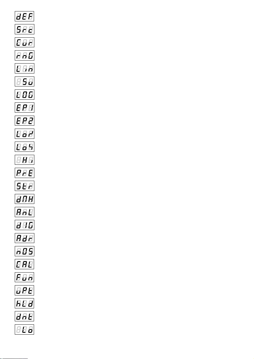
4. Symbols of shown messages................................................................................................
5. Device programming.............................................................................................................
5.1. Menu navigation..........................................................................................................
5.2. Setting control modes..................................................................................................
5.2.1. DMX control........................................................................................................
5.2.1.1. DMX addressing........................................................................................
5.2.1.2. Reaction to the lack of the DMX signal.....................................................
5.2.2. Analogue control................................................................................................
5.2.3. Control with buttons............................................................................................
5.3. Choice of the control curve..........................................................................................
5.4. Control range...............................................................................................................
5.5. Screen saving..............................................................................................................
5.6. Temperature.................................................................................................................
5.7. Working time................................................................................................................
5.8. Version of company software.......................................................................................
5.9. Default settings............................................................................................................
6. RDM......................................................................................................................................
7. Menu diagram.......................................................................................................................
8. Wiring diagram......................................................................................................................
9. Dimensions...........................................................................................................................
10. Technical data.....................................................................................................................
Declarations of conformity.........................................................................................................
The manufacturer reserves the right to change the operation and handling of the device in order
to improve the product.
tel.: (12) 385 83 06
fax: (12) 626 46 94
E-mail: [email protected]
Internet: www.pxm.pl
Rev 1.0
PXM Marek Żupnik spółka komandytowa
Podłęże 654
32-003 Podłęże

3
1. GENERAL DESCRIPTION
2. SAFETY CONDITIONS
PX741 is an intelligent transistor dimmer with phase cutting where control is carried out
on the falling edge (the so-called trailing edge dimming)
The module controls four channels 200VA each and has an built-in system of interference
suppression, fuses and signal controls.
The device has the DMX512 input, analogue inputs 0-10 V or a possibility to link outer buttons
and control them in compliance with one of four functions. The dimmer offers a lot of possibilities
to adjust the control characteristic.
Each of the four output channels can be configured individually.
The settings consist of the following parameters:
Ÿthe control mode (DMX, analogue, buttons)
ŸDMX address
Ÿthe reaction to the lack of the DMX signal
Ÿthe choice of key functions together with the full regulation of reaction time
Ÿadvanced functions and parameters allowing to adjust control to the type and characteristic of
capacity (a minimum and maximum level of control, a characteristic curve,
a function of pre-glow)
The dimmer is designated to work with capacity of R and RC types:
Ÿdimmable LED bulbs
ŸLEDs connected with a dimmable adapter of the CC type
Ÿtraditional bulbs
Ÿhalogen bulbs 230 V
Ÿhalogen bulbs 12 V connected with the dimmable electronic transformer
The device is closed in the standard housing of the width of 105 mm, designated for bar
assembling.
Dimmer PX741 is powered directly from standard 230V grid, what can cause electric shock when
safety rules are not observed. Therefore it is necessary to observe
the following :
1. Installation, particularly power connection, should be performed by a person holding
the appropriate qualifications, according to the description in the instruction manual.
2. Dimmers can be connected to socket which has protecting installation - separate PE
strand - in working order only (3-strand grid).
3. All the conductors should be protected against mechanical and thermal damage.

4. In the event of damaging any conductor, it should be replaced with a conductor of the same
technical data and attestations.
2
5. The external devices can be connected to the dimmer with 3-strand 0.75 mm minimum
crosssection area only.
6. Dimmer can be installed in closed electrical switching stations only, with restricted access
for people who does not handle proper qualifications in 230V supplied devices maintenance.
7. Power input must to be protected with an external residual current breaker with overload
of 6A rated current and B-type characteristic.
8. After the installation is completed, check the neutralization efficacy of all powered devices.
9. All repairs demanding casing opening should be made with cut off power supply.
10. The device should be strictly protected against water and other liquids.
11. All sudden shocks, particularly dropping, should be avoided.
12. Device with damaged (bent) casing should not be connected to the mains.
13. The device cannot be turned on in places with humidity exceeding 90%.
14. The device cannot be used in places with temperature lower than 2° C or higher than 40° C.
WARNING!!!
1. The inappropriate connection of a protective wire creates the risk of electric shock.
2. The inappropriate connection of the neutral wire results in the faulty operation of a dimmer.
3. The dimmer can regulate exclusively the circuits (of capacity) of the resistive type
or the capacitive one.
4

3. DESCRIPTION OF CONNECTORS AND CONTROL ELEMENTS
output 10V signal
Supply connector (starting from the left L4, L3, L2,
L1, 3xN, Lin and PE) L1-L4 are the output (con-
trolled) phases
DMX input analogue/digital inputs
4. SYMBOLS OF SHOWN MESSAGES
address of the DMX device – the elementary position in the MENU
setting parameters for each channel separately
current temperature value
blanc screen – screen saving ON/OFF
setting parameters for all the channels simultaneously
5
total working time
version of software

setting a linear control curve
setting a switched control curve
setting a logarithmic control curve
setting an exponential control curve with index 2
setting an exponential control curve with index 3
minimum level of an output connection while rising
minimum level of an output connection while falling
maximum control level
forcing a minimum output level
extension of an output curve to the full control range
channel control with the analogue input
channel control with the DMX signal
channel control with buttons
control range selection
control curve selection
control source selection
setting the DMX address
selection of the reaction mode to no DMX signal
reset to factory default settings
6
rise time in the push-button mode (from min to max)
calibration of analogue inputs
selection of one of four control functions
duration in the push-button mode (in function 4)
falling time in the push-button mode
minimum level which can be reached while dimming in function 2

first channel
total working time of the device
total duration of channel control
setting seconds
setting minutes
setting an hour
setting a day number
setting a year
infinity
inversion of the selected control curve
confirmation
setting a normal (non-inverted) selected control curve
switching off
switching on for 100%
setting the first function
scene: a control value for no DMX signal
7

5.1. Menu navigation
5. DEVICE PROGRAMMING
On switching on the device, the version of the programme appears for a moment on the display.
Press “previous” or “next” in order to select the appropriate menu and press “enter” to confirm
the choice.
5.2. Setting control modes
The menu of the PX741 device allows to set the control mode of the device.
Each of the device channels can be controlled with:
Ÿ the DMX dMX signal( ),
Ÿthe analogue input AnL,
Ÿthe buttons diG.
Setting the modes, the curve and the range of control is possible individually (Ind) for one of four
channels (CH1 – CH4) or collectively (ALL) for four channels simultaneously.
8
5.2.1.1. DMX addressing
In this menu, the DMX address can be set for individual channels individually or collectively for all
the channels simultaneously and then the set address will be designated to the first channel
and the next DMX addresses will be designated to next channels.
The address programmed this way cancels all the previous individual settings of each channel.
enterenter enter
enter
next
enter enter
next
next
enter
next
enter
enter
enter
5.2.1. DMX control
escape
previous
next
enter
- goes back to the previous MENU level or discards changes made
- scrolls to the previous feature on the same MENU level or decreases
the parameter's value
- scrolls to the next feature on the same MENU level or increases
the parameter's value
- enters the next MENU level and confirms changes made

5.2.1.2. Reaction to the lack of the DMX signal
This function is used both to secure the installation against disappearance of the DMX signal
and to achieve the desired value without the connection of an outer controller. On activating it,
in case of no DMX signal, the module will realize the selected option individually. The realized
option will be stopped automatically after re-connecting the DMX signal and the module will
realize commands sent through the DMX line again.
enterenter enter
enter
next
enter enter
next
next
enter
enter
enter enter
next
next
nextnext
prev
prev
prev
enter
next nextnext
prev
prev
prev
enter
next
next
next
next
next
Sc - programming the values of the scene, for which the following options are available:
Ÿthe value 0 - 255
Ÿmaintaining the last value of HLd
Ÿa signal from the analogue inputs AnL
Ÿa signal from the buttons diG
Apart from that, the transition parameters can be defined:
Ÿup time - uPt - the rise time in the push-button mode (from min to max)
Ÿhold - hLd - duration in the push-button mode (in function 4)
Ÿdown time - dnt - falling time in the push-button mode
SEC - setting seconds
Min ( ) - setting minutes
Hr - setting hours
dAY ( ) - setting days
9

5.2.2. Analogue control
enterenter
enter
next
enter
next
enter
enter
next
next
enter
next
enter
The control source from the analogue inputs can be set for each channel individually (Ind for the
channels CH1 – CH4) or collectively for all of them ALL. Calibration should be carried out
to ensure that the inputs work correctly. In order to do it, the maximum value should be set in the
input and the CAL option should be selected, and then the message YES should be confirmed
with the key “enter”.
wciśnięty
enter
wciśnięty
enter
10

5.2.3. Control with buttons
enterenter
next
enter
2x next
enter
next
next
next
next
next
next
next
enter
enter
next
enter enter
next 2x next
enter
next
next
next
next
next
next
next
enter
The control source form the digital inputs (with the buttons) can be set for each channel
individually (Ind for the channels CH1 – CH4) or collectively for all of them ALL.
The first step is to select one of four functions Fn1 – Fn4 (described on next pages), and then
to set its parameters.
uPt - rise time
hLd - duration
dnt - falling time
Lo - a minimum level which which can be reached while dimming in function 2
The list of operated parameters in each function is presented in the chart below.
Function
Available parameters
1
uPt, dnt
2
uPt, dnt, Lo
3
uPt, dnt
4
uPt, hld, dnt
11

FUNCTION DIAGRAMS FOR EXTERNAL BUTTON CONTROL
Function one
Function two
Time
Rise time
(parameter uPt)
Pressing
and holding
the key down
Releasing
the key
MAX
MIN
Time
Pressing
and holding
the key down
Short pressing
(<500 ms)
Releasing
the key
MAX
MIN
output
output
Lo
Falling time
(parameter dnt)
Falling time
(parameter dnt)
Rise time
(parameter uPt)
12

Each next short pressing of a key when the function realizes the parameter hLd causes that
the time of the parameter is counted from 0 (it resets the time elapsed), prolonging the operation
of the function at the same time. The value of this parameter is only taken into consideration
in the fourth function. It is ignored in other three functions.
Function three
Function four
Time
Short pressing
(<500 ms)
MAX
MIN
Time
duration
(parameter hLd)
Short pressing
(<500 ms)
MAX
MIN
output
output
Rise time
(parameter uPt)
Rise time
(parameter uPt)
Falling time
(parameter dnt)
Falling time
(parameter dnt)
13

5.3. Choice of the control curve
One of five control curves of the output can be selected for each channel:
Ÿlinear ( ) - the value on the output is linearly proportionate to the control value,
Ÿswitched ( ) - the two-stage characteristic,
Ÿlogarithmic,
Ÿexponential with index 2,
Ÿexponential with index 3.
The following options can be set for each control curve:
Ÿnormal ( ) - the value on the output is directly proportional to the value on the input
and in accordance with the chosen characteristic,
Ÿinverted ( ) - the value on the output is inversely proportional to the value on the
input and in accordance with the selected characteristic.
enterenter
enter
next
enter
next
next
next
enter
next
next
next
next
next
enter
next
next
next
next
Output
100%
0% 0255
127
linear
switched
logarithmic
exponential with index 2
exponential with index 3
The curves:
14

5.4. Control range
enterenter
enter
next
enter
next
next
2x next
enter
next
next
next
next
next
enter
next
next
next
next
The minimum and maximum control values and the manner of behaviour while reaching the limit
values can be defined for each channel:
ŸThe minimum level of connecting the output while rising ( )
ŸThe minimum level of connecting the output while falling ( )
ŸThe maximum level of control ( )
ŸForcing the minimum status on the output (when the channel is not controlled) ( )
ŸExtending the output curve to the full control range ( )
15

a) Str = OFF, PrE = On
Output
100%
Hi
Loä
Loæ
Output
100%
Hi
Loä
Loæ
Output
100%
Hi
Loä
Loæ
0255
0255
01 255
Below there are exemplary diagrams of control for the linear curve:
b) Str = OFF, PrE = OFF
c) Str = On, PrE = OFF
d) Str = On, PrE = On
Output
100%
Hi
Loä
Loæ
01 255
control level
value on the output
The curves:
16

17
5.5. Screen saving
The device was equipped with the possibility to switch off backlights for LED displays and
signalising diodes. The activated option bLc switches off the display after a period of one minute
of inactivity (when the buttons are not used). The device is still working without interference with
other parameters. To activate backlights, any key should be used.
On - switching on the option of screen saving
OFF - switching off the option of screen saving
enter
enter
next
2x next
5.6. Temperature
The device was equipped with the possibility to read the current temperature inside the device.
enter
enter
3x next
current temperature
in degrees Celsius
5.7. Working time
The dimmer was equipped with the possibility to read the total working time of the device.
Pwr ( ) - total working time of the device
Lht - total time of channel control
enter
enter
next
4x next

5.8. Version of company software
To verify the latest version of film software, the option Fir should be selected and then the key
"enter" should be pressed to confirm.
enter
enter
5x next
5.9. Default settings
To restore the factory default values, the dEF option should be selected and the key "enter"
should be kept longer. Then, when the message YES appears, confirm with the key "enter".
It is also possible to exit from the level of this menu without the return to the factory default
settings. In this case the key "escape" should be selected.
enter
wciśnięty
enter
6x next
18

6. RDM
The PX741 supports the DMX-RDM protocol. DMX protocol allows only of a one-way data
transmission, while its extension the RDM protocol can transmit information in two directions.
This makes possible to simultaneously send and receive information, and hence the possibility
of monitoring activities of the compatible devices. Thanks to RDM some available settings
of compatible devices may be programmed using this protocol.
19
Below is a list of RDM parameters supported by the PX741:
Parameter name
PiD
Description
SUPPORTED_PARAMETERS
0x0050
all supported parameters
PARAMETER_DESCRIPTION
0x0051
description of additional parameters
DEVICE_INFO
0x0060
information concerning the device
SOFTWARE_VERSION
0x00C0
firmware version of the device
DMX_START_ADDRESS *
0x00F0
DMX starting address of the device;
minimum value: 1, maximum value: 512. According
to the RDM standard, for device whose footprint is
0, the value of this parameter may be 65535 and
then it is not possible to change the initial address
settings for the entire device, but only for
sub-devices.
IDENTIFY_DEVICE *
0x1000
device identification;
Two states are possible: identification is off
(0x00 value) and identification is on (0x01 value).
DEVICE_MODEL_
DESCRIPTION
0x0080
device description, e.g. name
MANUFACTURER_LABEL
0x0081
manufacturer description, e.g. name
DEVICE_LABEL *
SUBDEVICE_LABEL *
0x0082
additional device description;
It is possible to enter an additional device
description using up to 32 ASCII characters.
DMX_PERSONALITY
0x00E0
DMX operational mode
DEVICE_HOURS
0x0400
information concerning the working time of the
device counted in hours
SENSOR_DEFINITION
0x0200
information on the selected sensor of temperature
SENSOR_VALUE
0X0201
information on sensors
CONTROL_HOURS
0x0401
FACTORY_DEFAULTS
0x0090
factory default settings of the device
DIGITAL_MODE
0x8039
setting the control mode of the channel with the
buttons

20
Parameter name
PiD
Description
DIGITAL_RISE_TIME
0x8056
setting the rise time for control with the buttons;
setting from 0 to 24h, in units 100ms
DIGITAL_LAST_TIME
0x8057
setting the duration for control with the buttons;
setting from 0 to 24h, in units 100ms
DIGITAL_FALL_TIME
0x8058
setting the falling time for control with the buttons;
setting from 0 to 24h, in units 100ms
DIGITAL_MIN_LEVEL
0x8059
setting the minimum level which can be reached
while dimming for the control mode with the
buttons; setting from 0-50%
OUTPUT_CURVE
0x8049
selection of the control curve;
setting from 0 to 24h, in units 100ms
OUTPUT_CURVE_INVERT
0x804F
selection of the invert function for the previously set
curve;
functions to be selected: 0 normal, 1 invert
MINIMUM_LEVEL_INC.
0x804A
minimum level of connecting the output while rising;
the value selection from 0 to 100
MINIMUM_LEVEL_DEC.
0x805A
minimum level of connecting the output while
falling;
the value selection from 0 to 100
MAXIMUM_LEVEL
0x8048
maximum level of control;
the value selection from 0 to 100
PREHEAT
0x805B
forcing the minimum level on the output (when the
channel is not controlled);
to be selected: 0 (switching off), 1 (switching on)
STRECH_OUTPUT
0x805C
extending the output curve to the full control range;
to be selected: 0 (switching off), 1 (switching on)
NOS_VALUE
0x801C
setting the reaction to the disappearance of DMX
signal;
to be selected: -1 for the option of maintaining the
las value, -2 for the analogue control, -3 for control
with the buttons. The choice from 0 to 255 for
control with the DMX values.
NOS_RISE_TIME
0x805D
falling time;
setting from 0-24h, in units 100ms or infinity
(0xFFFFFFFF)
NOS_LAST_TIME
0x805E
lasting time;
setting from 0-24h, in units 100ms or infinity
(0xFFFFFFFF)
NOS_FALL_TIME
0x805F
falling time;
setting from 0-24h, in units 100ms
* - editable parameter
Other manuals for PX741
1
Table of contents
Other PXM Dimmer manuals