manuals.online logo
Brands
  1. Home
  2. •
  3. Brands
  4. •
  5. Elko
  6. •
  7. Dimmer
  8. •
  9. Elko DIM-15 User manual

Elko DIM-15 User manual

1 / 2
DIM-15
02-89/2016 Rev.: 0
abcde f
R
LC
xx xx xxx
zzzzzzz
230V AC
6
8
1
2
3
7
5
4
A2
A1
V
T
L
N
A2 T
A1 V
ELKO EP, s.r.o.
Palackého 493
769 01 Holešov, Všetuly
Czech Republic
Tel.: +420 573 514 211
e-mail: [email protected]
www.elkoep.com
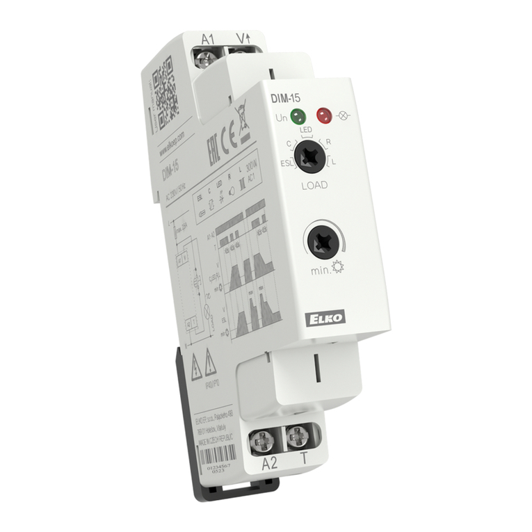
Controlled dimmer
• designated for dimming of:
R - bulbs, halogen lamps
L - low-voltage el. bulbs 12/24 V wound transformers
C - low-voltage el. bulbs 12/24 V electronic transformers
ESL - dimmable compact uorescent lamps
LED - LED lamps
• enables gradual setting of luminance by push-button (non-detent) or parallel buttons
• returns to last state upon re-energization
• type of light source is set by switch-over on the front panel of device
• min. luminance, set by potentiometer on the front panel, eliminates ashing of light
sources
• supply voltage 230 V AC
• output status is indicated by red LED:
- shines when output is active (with arbitrary luminance intensity)
- ashes while heating overload, at the same time output is disconnected
• 1-MODULE version, DIN rail mounting, saddle terminals
Mounting recommendation:
- on each side of device keep a gap with width 0.5 of module (cca 9 mm) for better device
cooling
Warrning:
- it is not recommended to connect light sources with dierent types and brands, to one
dimmer
Characteristics
Description
Symbol
Connection
EN
1. Supply voltage L
2. Supply voltage indication
3. Light source type selection:
ESL - dimmable compact uorescent lamps
C - low-voltage el. bulbs 12/24 V electronic
transformers
LED - LED lamps
R - bulbs, halogen lamps
L - low-voltage el. bulbs 12/24 V wound
transformers
4. Supply voltage N
5. Output
6. Output indication
7. Minimal luminance setting
8. Controlling input
T 2.5 A - ballast protection recommended
a) lamp,halogen light
b) low-voltage el.bulbs 12/24V wound transformers
c) low-voltage el.bulbs 12/24V electronic transformers
d) LED bulbs
e) saving uorescent lamps
f) switching management
x - dimmable
xx - incline edge
xxx - descending edge
Product loadability
2 / 2
DIM-15
A1-A2
T
V
R, L, C, LED
min
V
ESL
min
>0.5s <0.5s<0.5s >0.5s
max max
<0.5s
Warning
Technical parameters
Device is constructed for connection in 1-phase main AC and must be installed according
to norms valid in the state of application. Connection must be realized according to the
details in this instruction manual. Installation, connection, setting and operating should
be made by qualied electrician sta only, who has learnt these instruction and functions
of the device. This device contains protection against overvoltage peaks and disturbancies
in supply. For correct function of the protection of this device there must be a suitable
protections of higher degree (A, B, C) installed in front of them. Before installation the main
switch must be in position “OFF”and the device should be de-energized. Don´t install the
device to sources of excessive electro-magnetic interference. By correct installation ensure
ideal air circulation so in case of permanent operation and higher ambient temperature
the maximal operating temperature of the device is not exceeded. For installation and
setting use screw-driver cca 2 mm. The device is fully-electronic - installation should be
carried out according to this fact. Non-problematic function depends also on the way of
transportation, storing and handling. In case of any signs of destruction, deformation, non-
function or missing part, don´t install and claim at your seller. After the product exceeds
lifetime, it should be removed and placed in protected dump.
Important instructions and cautions - dimmer is not designated for controlling of motors
or other inductive loads. HDO warning signals and other similar signals spreaded by main,
can cause interruption of dimmer. Interruption is active only during transmitting of these
signals.
Function
Supply terminals:
Supply voltage:
Supply voltage tolerance:
Apparent power:
Loss power:
Supply indication:
Controlling
Control terminals:
Control voltage:
Control input power:
Control impulse lenght:
Glow tubes connection:
Max. amount of glow lamps
connected to controlling
input:
Output
Contactless:
Load:
Output status indication:
Other data
Operating temperature:
Storage temperature:
Operating position:
Mounting:
Protection degre:
Overvoltage category:
Pollution degree:
Max. cable size (mm2):
Dimensions:
Weight:
Standards:
A1 - A2
AC 230 V / 50 Hz
-15 %; +10 %
max. 1.5 VA
max. 0.7 W
green LED
A1 - T
AC 230 V
AC 0.3 - 0.6 VA
min. 80 ms / max. unlimited
yes
max. 15 pcs
(measured with glow lamp 0.68 mA / 230 V AC)
2x MOSFET
300 W (at cos φ =1)*
red LED
-20 °C to +35 °C (-4 °F to 95 °F)
-20 °C to +60 °C (-4 °F to 140 °F)
any
DIN rail EN 60715
IP40 from front panel, IP10 terminals
III.
2
max. 2x 2.5, max. 1x 4 /
with sleeve max. 1x 2.5, max. 2x 1.5 (AWG 12)
90 x 17.6 x 64 mm (3.5˝ x 0.7˝ x 2.5˝)
57 g (1.98 oz.)
EN 60669-2-1, EN 61010-1
* Due to a large number of light source types, the maximum load depends on the internal
construction of dimmable light sources and their power factor cos φ. The power factor
of dimmable LEDs and ESL bulbs ranges from cos φ = 0.95 to 0.4. An approximate value
of maximum load may be obtained by multiplying the load capacity of the dimmer by
the power factor of the connected light source.
Controlling:
- short button press (< 0.5 s) turns the light o or on
- long press (> 0.5 s) enables slight regulation of light intensity
- setting of minimal luminance is possible only during decreasing of luminance by long
button press
- setting of minimal luminance by saving uorescent lamps serves for harmonizing of
lowest light intensity prior its unprompted switching o
Luminance setting:
R, L, C, LED - if the light is turned o, short press (< 0.5 s) switches the light onto last set
luminance level
ESL - if the light is turned o, short press increases the luminance onto maximal level
(saving uorescent lamps res up) and then luminance decreases onto set level.
Notice:
- it is not possible to dim saving uorescent lamps without marking: dimmable
- an incorrect setting of light source has eect only on dimming range, it means neither
dimmer or load get demaged
- the maximum number of dimmable light sources depends on their internal construction
- actual list of tested light sources is constantly refreshing, further information on
www.elkoep.com
Other Elko Dimmer manuals

Elko iNELS RFDEL-71B-SL User manual

Elko

Elko iNELS RFDEL-71B-SL User manual

Elko EKO0725X User manual

Elko

Elko EKO0725X User manual

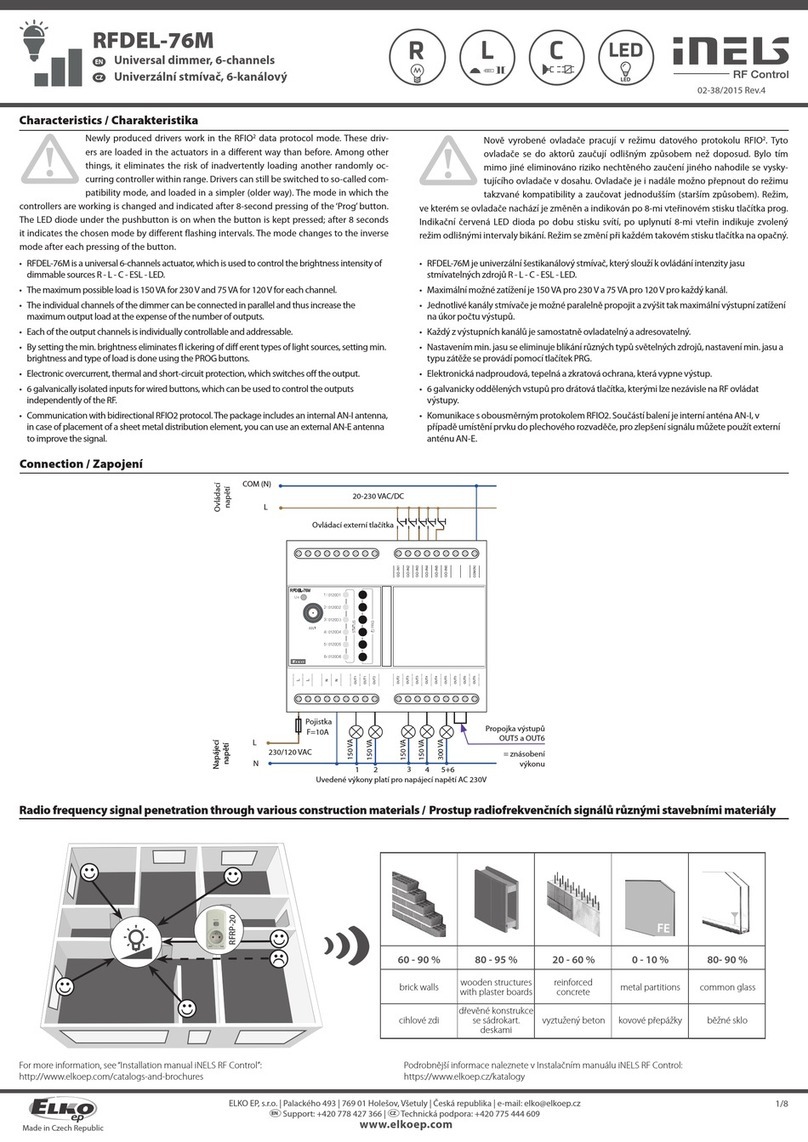
Elko iNels RFDEL-76M User manual

Elko

Elko iNels RFDEL-76M User manual

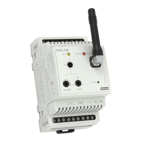
Elko Inels  RFDEL-71M User manual

Elko

Elko Inels RFDEL-71M User manual

Elko iNels RFDEL-71B-SL User manual

Elko

Elko iNels RFDEL-71B-SL User manual

Elko DIM-6 User manual

Elko

Elko DIM-6 User manual

Elko iNELS RFDEL-71B-SL User manual

Elko

Elko iNELS RFDEL-71B-SL User manual

Elko iNELS RFDEL-71B-SL User manual

Elko

Elko iNELS RFDEL-71B-SL User manual

Elko SmartMove Multiwire Dimmer Push User manual

Elko

Elko SmartMove Multiwire Dimmer Push User manual

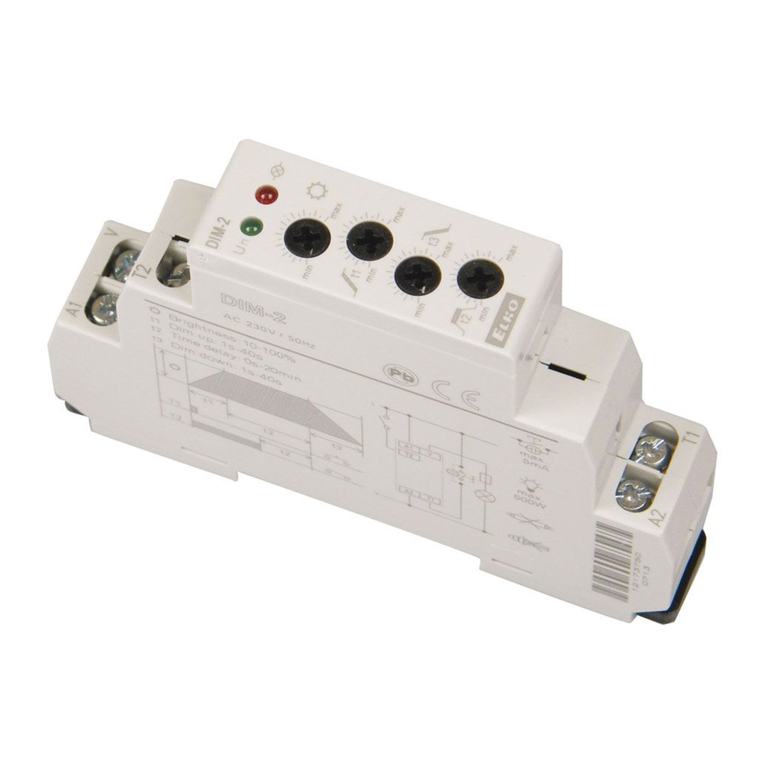
Elko DIM-2 User manual

Elko

Elko DIM-2 User manual

Elko DIM-15 User manual

Elko

Elko DIM-15 User manual

Elko iNELS RFDEL-71B-SL User manual

Elko

Elko iNELS RFDEL-71B-SL User manual

Elko RFDEL-76M User manual

Elko

Elko RFDEL-76M User manual

Elko iNELS RFDEL-71B-SL User manual

Elko

Elko iNELS RFDEL-71B-SL User manual

Elko iNELS RFDEL-71B-SL User manual

Elko

Elko iNELS RFDEL-71B-SL User manual

Popular Dimmer manuals by other brands

Stairville D1210T user manual

Stairville

Stairville D1210T user manual

Leviton i Series e user guide

Leviton

Leviton i Series e user guide

Linear Technology Sys-Pro 114460 quick start guide

Linear Technology

Linear Technology Sys-Pro 114460 quick start guide

Leviton 6615-P installation instructions

Leviton

Leviton 6615-P installation instructions

GVS KA/D 0103.1 user manual

GVS

GVS KA/D 0103.1 user manual

Elation DP-640B instruction manual

Elation

Elation DP-640B instruction manual

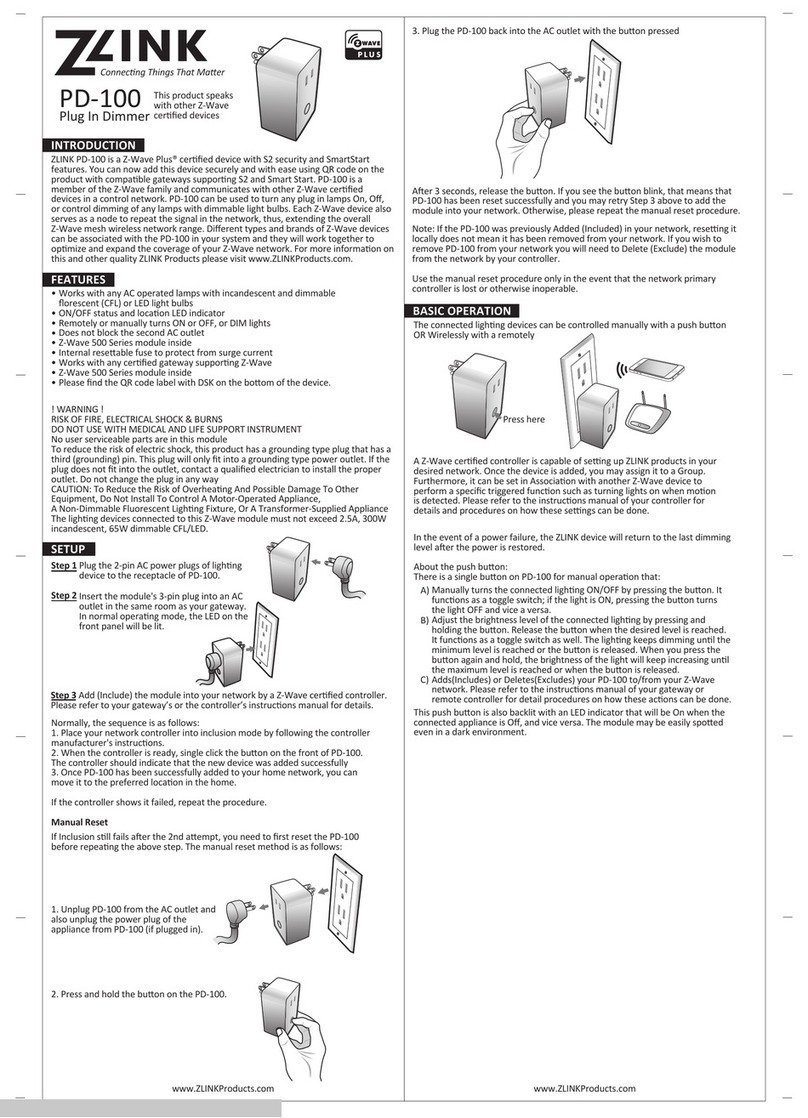
ZLINK PD-100 instruction manual

ZLINK

ZLINK PD-100 instruction manual

AMX Dual Incandescent Dimmer Module RDM-2INC Installation sheet

AMX

AMX Dual Incandescent Dimmer Module RDM-2INC Installation sheet

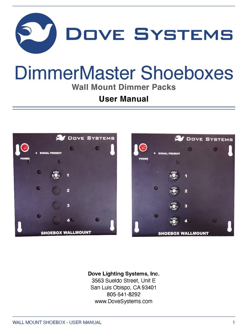
Dove Lighting Systems DimmerMaster user manual

Dove Lighting Systems

Dove Lighting Systems DimmerMaster user manual

Contro l4 C4-KD120 installation guide

Contro l4

Contro l4 C4-KD120 installation guide

Contro l4 8-Channel Operation guide

Contro l4

Contro l4 8-Channel Operation guide

Contro l4 C4-KD120 Series installation guide

Contro l4

Contro l4 C4-KD120 Series installation guide

DekoLight Multi Dimmer 4 manual

DekoLight

DekoLight Multi Dimmer 4 manual

Contro l4 C4-APD120 quick start guide

Contro l4

Contro l4 C4-APD120 quick start guide

WorkPro MINIDIM 1 user manual

WorkPro

WorkPro MINIDIM 1 user manual

MCOHome MH-P411 user manual

MCOHome

MCOHome MH-P411 user manual

Nicols DP 615 instruction manual

Nicols

Nicols DP 615 instruction manual

FIBARO WALLI FGWDEU-111 operating manual

FIBARO

FIBARO WALLI FGWDEU-111 operating manual

manuals.online logo
manuals.online logoBrands
  • About & Mission
  • Contact us
  • Privacy Policy
  • Terms and Conditions

Copyright 2025 Manuals.Online. All Rights Reserved.