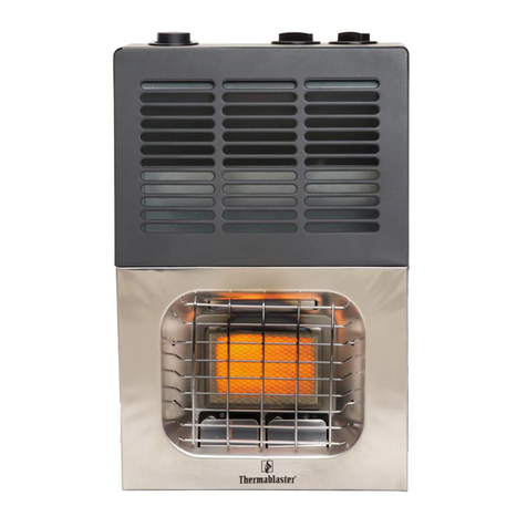
Thermablaster RC9200IT User manual

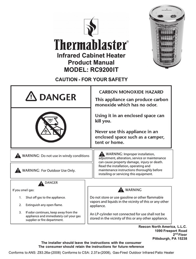
Infrared Cabinet Heater
Product Manual
MODEL: RC9200IT
CAUTION - FOR YOUR SAFETY
Reecon North America, L.L.C.
1090 Freeport Road
2nd Floor
Pittsburgh, PA 15238
The installer should leave the instructions with the consumer
The consumer should retain the instructions for future reference
Conforms to ANS: Z83.26a-(2008) Conforms to CSA: 2.37a-(2008), Gas-Fired Outdoor Infrared Patio Heater (except wind)

2
PRODUCT SPECIFICATIONS
Model RC9200IT
BTU(available)32,000
BTU(9.2Kw)
Gas type LP
Pressure regulator
setting 11 WC
Maximum Inlet Gas
Supply Pressure 11 WC
Ignition Electric Piezo
Heat Setting 2 stage (Hi/Low)
1. IMPORTANT SAFETY INFORMATION
IMPORTANT: Read this owner’s manual carefully and completely before trying to assemble, operate, or
service this heater. Improper use of this heater can cause serious injury or death from burns, fire,
explosion, electrical shock, and carbon monoxide poisoning. Only a qualified installer, service agent, or
local gas supplier may install and service this product.
WARNING: Do not store or use gasoline or other flammable vapors and liquids in the vicinity of this
or any other appliance.
CARBON MONOXIDE POISONING: Early signs of carbon monoxide poisoning resemble the flu with
headache, dizziness and/or nausea. If you have these signs, heater may not be working properly. Get
fresh air at once! Have heater serviced. Some people - pregnant women, persons with heart or lung
disease, anemia, those under the influence of alcohol, those at high altitude - are more affected by
carbon monoxide than others.
WARNING: Any change to this heater or its controls can be dangerous.
WARNING: Do not use any accessories not approved for use with this heater.
WARNING: Carefully supervise young children when they are in the area with the heater.
WARNING: Make sure both grill guards are in place before running the heater.(see diagram page 4)
WARNING: Keep the appliance area clear and free from combustible materials, gasoline, and other
flammable vapors and liquids.
WARNING: Due to high temperatures, the appliance should be located out of traffic and away from
furniture and draperies.

3
WARNING: Certain materials or items, when stored under the heater, will be subjected to radiant
heat and could be seriously damaged.
WARNING: Heater becomes very hot when running. Keep children and adults away from hot
surfaces to avoid burns or clothing ignition. Heater will remain hot for a time after shutoff.
Allow surfaces to cool before touching.
WARNING: Do not place clothing or other flammable material on or near the appliance. Never place
any objects in the heater.
WARNING: Failure to keep the primary air opening(s) of the burn(s) clean may result in sooting and
property damage.
WARNING: Do not allow fans to blow directly into the heater. Avoid any drafts that alter burner
flame patterns. Do not use in windy conditions.
WARNING: Do not use a blower insert, heat exchanger insert or other accessory not approved for
use with this heater
WARNING: Failure to position the parts in accordance with these diagrams or failure use only parts
specifically approved with this heater may result in property damage or personal injury.
This heater needs fresh air ventilation to run properly. This heater has an Oxygen Depletion Sensing
(ODS) safety shutoff system. The ODS shuts down the heater if not enough fresh air is available.
See Air for Combustion and Ventilation.
DO NOT RUN HEATER: Where flammable liquids or vapors are used or stored or under dusty
conditions.
Always run heater with control knob locked positions. Never set control knob between locked positions.
Poor combustion and higher levels of carbon monoxide may result.
Periodic visual check of pilot and burner flame, are necessary for proper operation.
QUALIFIED INSTALLING AGENCY
Only a qualified agency should install and replace gas piping, gas utilization equipment or
accessories, and repair and equipment servicing. The term “qualified agency” means any individual, firm,
corporation, or company that either in person or through a representative is engaged in and is
responsible for:
a) Installing, testing, or replacing gas piping or
b) Connecting, installing, testing, repairing, or servicing equipment; that is experienced in such work; that
is familiar with all precautions required; and that has complied with all the requirement of the authority
having jurisdiction.

4
2. PRODUCT FEATURES
SAFETY PILOT
This heater has a pilot with an Oxygen Depletion Sensing (ODS) safety shutoff system. The ODS pilot
shuts off the heater if there is not enough fresh air.
TIP OVER SWITCH
This heater is equipped with a safety tip over switch in the event the heater is knocked over.
PIEZO IGNITION SYSTEM
This heater is equipped with an electronic piezo control system.
3. PREPARING FOR INSTALLATION
Before beginning assembly or operation of the product, make sure all parts are present. Compare parts
with package contents list and diagram below. If any part is missing or damaged, do not attempt to
assemble, install or operate the product. Contact customer service for replacement parts.
Figure 1 – gas heater cabinet
UNPACKING
1. Remove heater from carton.
2. Remove all protective packaging applied to heater for shipping
3. Check heater for any shipping damage. If heater is damaged, promptly inform dealer where you bought
heater.
Igniter button Control knob
Protective front cover

5
4. INSTALLATION
WARNING: A qualified service person must install heater. Follow all local codes.
Check Gas Type
Be sure your gas supply is right for your heater. Otherwise, call dealer where you bought the
heater for proper type heater.
Connect Hose & Regulator to Cylinder
1) You must provide propane gas and propane cylinder. Use a standard 20 lb.
propane cylinder. (See figure 2)
2) Use this heater only with a propane vapor withdrawal supply system. See chapter
5 of the standard for storage and handling of liquefied petroleum Gas, ANSI/NFPA58.
Your local library or fire department should have this book.
3) The minimum permissible gas supply inlet pressure of 11 W.C. is required for
purpose of input adjustment.
4) The normal hourly of 32,000BTU is required input rating for a heater for automatic
operation at ratings less than full input rating.
Figure 2 – propane cylinder
5) The pressure regulator and hose assembly supplied with the appliance must be used.
6) The regulator hose must be attached to the tank and the heater inside the heater cabinet. This will
make sure the hose is located out of pathways where people may trip over it or in areas where the hose
may be subject to accidental damage.
7) The installation must conform with local codes, or in the absence of local codes, with National Fuel
Gas Code, ANSI Z223.1.
8) LP-gas supply cylinder to be used must be:
(a) Constructed and marked in accordance with the Specifications for LP-gas cylinders of the U.S.
Department of Transportation (DOT); or the Standard for Cylinders, Spheres and Tubes for
Transportation of Dangerous Goods and Commission, CAN/CSA-B339, as applicable;
(b) Provided with a listed overfilling prevention device; and
(c) Provided with a cylinder connection device compatible with the connection for the appliance.
9) A dented, rusted or damaged propane cylinder may be hazardous and should be
checked by your cylinder supplier. Never use a propane cylinder with a damaged
valve connection.
10) The propane cylinder must be constructed and marked in accordance with the
specifications for LP gas cylinders of the U.S. Department of Transportation (DOT).
11) Never connect an unregulated propane cylinder to the heater. figure 3

6
12) Screw regulator onto gas hose. Dot not cross-thread. (see figure 3)
13) Tighten securely.
14) Attach regulator to cylinder. (see figure 4)
figure 4
15) Complete attachment.
16) Install the cylinder and latch closed. (see figure 5)
17) Close the rear cover.
18) Attach the primary AND secondary protective grills using the screws
provided with the heater. Ensure both screw holes on each side of both grills
are securely fastened to the heater. (Please see diagram on page 14 showing
both grills separately and also there attached position to the heater)
figure 5
CHECKING GAS CONNECTIONS
WARNING: Test all gas piping and connections for leaks after installing or servicing. Correct all
leaks at once.
WARNING: Never use an open flame to check for a leak. Apply a mixture of liquid soap and water to
all joints. If bubbles form, there is a leak. Correct all leaks at once.
Pressure Testing Heater Gas Connections
1) Open gas supply tank valve.
2) Make sure control knob of heater is in the OFF position.
3) Check all joints from equipment shutoff valve to control valve. Apply mixture of liquid soap and
water to gas joints. If bubbles form, there may be a leak.
4) Correct all leaks at once.

7
5. AIR FOR COMBUSTION AND VENTILATION
This heater is equipped with multiple ventilation holes in and around the heater. The following
MUST be adhered to when using this heater:
1) Adequate clearance MUST always be provided for the air opening around the heater.
2) Adequate air MUST be provided into the combustion chamber.
3) This heater MUST always be kept clear of ANY combustible material.
The following are the minimum clearances from combustibles:
1) 4 inches from the floor
2) 5 feet from ANY wall or railing
3) 8 feet from the ANY ceiling or overhead cover
USER MUST NEVER OPERATE THE HEATER WITH ANY VENT COVERED TO ALLOW ADEQUATE
FRESH AIR INTO THE HEATER AND COMBUSTION CHAMBER
6. OPERATION
FOR YOUR SAFETY READ BEFORE LIGHTING
WARNING: If you do not follow these instructions exactly, a fire or explosion may result causing
property damage, personal injury or loss of life.
Before Turning Gas Supply ON:
1) Your heater was designed and approved for outdoor use only. Do NOT use it inside a building, garage,
or any other enclosed area.
2) Make sure surrounding areas are free of combustible materials, gasoline, and other flammable vapors
or liquids.
3) Ensure that there is no obstruction to air ventilation.
4) Be sure all gas connections are tight and there are no leaks by using soap on the hose. No bubbles
should be seen. If you see bubbles then the connection is not secure.
5) Inspect the gas pressure regulator and hose prior to each use. (if there is evidence of
excessive abrasion or wear, or if the hose is damaged DO NOT USE THE HEATER. The user
MUST replace the hose with the manufacture specified replacement hose and regulator)
6) Regulator Hose should be connected at the top of the propane cylinder and attached directly to the
heater out of the way area where accidental damage could occur.
7) ONLY the pressure regulator and hose assembly supplied with the appliance must be used
8) Be sure the cylinder cover is clear of debris.
9) Be sure any component remove during assembly or servicing is replaced & fastened prior to starting.

8
Before lighting
1) Heater should be thoroughly inspected before each use and by a qualified service person at least
annually.
2) If relighting a hot heater, always wait at least 5 minutes
3) Inspect the hose assembly for evidence of excessive abrasion, cuts, or wear. Suspected areas should
be leak tested. If the hose leaks, it must be replace prior to operation. Only use the replacement hose
assembly specified by manufacturer.
Lighting
1) STOP! Read the safety information on the inside of the heater. User MUST follow these lighting
procedures or the heater will NOT operate properly.
2) Make sure equipment shutoff valve is fully open.
3) Turn control knob clockwise to the OFF position.
4) Wait five (5) minutes to clear out any gas. Then smell for gas, including near the floor. If you smell
gas, STOP! Do not try to light any appliance. Do not touch electrical switch or use any phone in the
building. Immediately contact gas supplier from a neighbor’s phone. Follow gas supplier’s
instructions. If you can’t reach the gas supplier, call the fire dept. If you don’t smell gas, go to the
next step.
5) Turn control knob counterclockwise to the START position. Press in control knob for five (5)
seconds (see the follow Figure 6) and simultaneously press the igniter button. This will light the
pilot. The user must verify the pilot is lit prior to turning the knob to the first flame position. In the
event the pilot is not lit you must wait 5 minutes to relight.
6) Turn control knob to single flame symbol. This will light the bottom 3 ceramic plaques.
7) Turn the knob again to the double burner symbol and this will light the upper 3 ceramic plaques.
(it is best to allow the bottom 3 plaques to warm up first prior to turning the top plaques on.)
figure 6 figure 6.1

9
Shut down
1) Turn control knob clockwise to START (normally, burner will make a slight popping sound when
extinguished.)
2) To extinguish pilot, depress control knob and continue to turn it clockwise to OFF.
3) Turn cylinder valve clockwise to OFF and disconnect regulator when heater is not in use.
After operation check:
1) Gas control is in OFF position.
2) Gas Tank valve is OFF.
3) Disconnect gas hose by unscrewing the plastic end attached to the cylinder.
4) Heater is upright in a secure location.
5) Storage of an appliance indoors is permissible only if the cylinder is disconnected and removed
from the appliance.
6) A cylinder must be stored outdoors in a well-ventilated area out of the reach of children
7) A disconnected cylinder must have dust caps tightly installed and must not be stored in a building,
garage or any other enclosed area.
7. CARE AND MAINTENANCE
WARNING: Turn off heater and let cool before servicing. Any grills removed for servicing MUST be
replaced prior to use.
CAUTION: You must keep control areas, burner, and circulating air passageways of heater clean.
Inspect these areas of heater before each use. Have heater inspected yearly by a qualified service
technician. Heater may need more frequent cleaning due to dirt and other debris normally found
outdoors.
CAUTION: The appliance is equipped with a piezo electric operated ignition device. The user MUST
follow the proper lighting instructions or damage to the heater or fire may occur.
CLEANING ODS/PILOT AND BURNER
Use a vacuum cleaner, pressurized air, or a small, soft bristled brush to clean.

10
CLEANING BURNER PILOT AIR INLET HOLE
We recommend that you clean the unit every 2,500 hours of operation or every three months. We also
recommend that you keep the burner tube and pilot assembly clean and free of dust and dirt. To clean
these parts we recommend using compressed air no greater than 30 PSl. Your local computer store,
hardware store, or home center may carry compressed air in a can. You can use a vacuum cleaner in the
blow position. If using compressed air in a can, please follow the directions on the can. If you don’t follow
directions on the can, you could damage the pilot assembly.
1) Shut off the unit, including the pilot. Allow the unit to cool for at least thirty minutes.
2) Inspect burner and pilot for dust and dirt.
3) Blow air through the ports/slots and holes in the burner and clean the pilot assembly. A yellow tip
on the pilot flame indicates dust and dirt in the pilot assembly. There is a small pilot air inlet hole
about two inches from where the pilot flame comes out of the pilot assembly (see figure 7). With
the unit off, lightly blow air through the air inlet hole. You may blow through a drinking straw if
compressed air is not available.
4) With the unit on, visually check the burner flames to very an even orange pattern on ALL 6 burners.
Compare with figure 7 below.
Insert air cleaning decide through grill to clean burner holes
Figure 7
CLEANING THE CABINET
Air Passageways
Use a vacuum cleaner or pressurized air to clean.
Exterior
Use a soft cloth dampened with a mild soap and water mixture.
Wipe the cabinet to remove dust.
If you need replacement parts you must go to an authorized dealer for professional service!
Every part of the heater shall be secure against displacement and shall be constructed to maintain a fixed
relationship between essential parts under normal and reasonable conditions of handling and usage.
Parts not permanently secured shall be designed so they cannot be incorrectly assembled and cannot be
improperly located or misaligned in removing or replacing during cleaning or other servicing.

11
8. TROUBLE SHOOTING
WARNING: If you smell gas:
1) Open the window and door immediately.
2) Shut off gas supply.
3) Do not try to light any appliance.
4) Do not touch any electrical switch; do not use any phone in your building.
5) Immediately call your gas supplier from a neighbor’s phone. Follow the gas supplier’s instructions.
6) If you cannot reach your gas supplier, call the fire department.
IMPORTANT: Operating heater where impurities in air exist may create odors. Cleaning supplies, paint,
paint remover, cigarette smoke, cements and glues, new carpet or textiles, etc., create fumes. These
fumes may mix with combustion air and create odors.
WARNING: Only a qualified service technician should service and repair heater.
CAUTION: Never use a wire, needle, or similar object to clean ODS pilot. This can damage ODS pilot
unit. Note: All troubleshooting items are listed in order of operation.

12
No. PROBLEM POSSIBLE CAUSE REMEDY
1 When igniter button is pressed in
there is no spark at ODS/pilot.
1. Igniter electrode is positioned
wrong or broken.
2. Igniter electrode is not connected to
igniter cable.
3. Igniter cable is pinched or wet.
4. Broken igniter cable.
5. Bad piezo igniter.
1. Replace igniter.
2. Reconnect igniter cable.
3. Free igniter cable if pinched by any
metal or tubing. Keep igniter cable dry.
4. Replace igniter cable.
5. Replace piezo igniter.
2 When igniter button is
pressed in there is a spark
at ODS/pilot but no ignition.
1. Gas supply is turned off or
equipment
Shutoff valve is closed.
2. Control knob not fully pressed in
while
pressing igniter button.
3. Air in gas lines when installed.
4. ODS/pilot is clogged.
5. Gas regulator setting is not correct.
6. Control knob not in PILOT position.
7. Depleted gas supply (propane).
1. Turn on gas supply or open equipment
shutoff valve.
2. Fully press in control knob while
pressing igniter button.
3. Continue holding down control knob.
Repeat igniting operation until air is
removed.
4. Clean ODS/pilot (see Care and
Maintenance, page 9) or replace ODS/
pilot assembly.
5. Replace gas regulator.
6. Turn control knob to PILOT position.
7. Contact local propane/LP gas company.
3 ODS/pilot lights but flame
goes out when control
knob is released.
1. Control knob is not fully pressed in.
2. Control knob is not pressed in long
enough.
3. Equipment shutoff valve is not
fully open.
4. Thermocouple connection is loose
at control valve.
5. Thermocouple damaged.
6. Control valve damaged.
1. Press in control knob fully.
2. After ODS/pilot lights, keep control knob
pressed in 30 seconds.
3. Fully open equipment shutoff valve
4. Hand tighten until snug, and then
tighten 1/4 turn more.
5. Replace thermocouple.
6. Contact customer service.
4 Burner(s) does not light
after ODS/pilot is lit.
1. Burner orifice is clogged.
2. Burner orifice diameter is too small.
3. Inlet gas pressure is too low.
1. Clean burner orifice (see Care and
Maintenance, page 10) or replace
burner orifice.
2. Contact customer service.
3. Contact local gas supplier.
5 Delayed ignition of
burner(s).
1. Manifold pressure is too low.
2. Burner orifice is clogged.
1. Contact local gas supplier.
2. Clean burner (see Care and
Maintenance, page 10) or replace
burner orifice.
6 Burner backfiring
during combustion.
1. Burner orifice is clogged or
damaged.
2. Burner is damaged.
3. Gas regulator is defective.
1. Clean burner orifice (see Care and
Maintenance, page 10) or replace.
2. Contact customer service.
3. Replace gas regulator.
7 Yellow flame during
burner combustion. 1. Not enough air.
2. Gas regulator is defective.
3. Inlet gas pressure is too low.
1. Check burner for dirt and debris. If
found, clean burner (see Care and
Maintenance, page 10).
2. Replace gas regulator.
3. Contact local gas supplier.
8 Slight smoke or odor
during initial operation.
1. Residues from manufacturing
processes.
1. Problem will stop after a few hours of
operation.
9 Heater produces a
whistling noise
when burner is lit.
1. Turning control knob to HI position
when burner is cold.
2. Air in gas line.
3. Air passageways on heater are
blocked.
4. Dirty or partially clogged burner
orifice.
1. Turn control knob to LO position and let
warm up for a minute.
2. Operate burner until air is removed
from line. Have gas line checked by
local gas supplier.
3. Observe minimum installation
clearances (Section 5 page 7).
4. Clean burner (see Care and
Maintenance, page 10) or replace

13
burner orifice.
10 Heater produces a
clicking/ ticking noise
just after burner is lit
or shut off.
1. Metal is expanding while
heating or contracting while
cooling.
1. This is common with most heaters. if
noise is excessive, contact qualified
service technician.
11 White powder residue
forming within burner box
or on adjacent walls or
furniture.
1. When heated, the vapors from
furniture polish, wax, carpet cleaners,
etc., turn into white powder residue.
1. Turn heater off when using furniture
polish, wax, carpet cleaner, or similar
products.
12 Heater produces
unwanted odors.
1. Heater is burning vapors from
paint, hair spray, glues, etc.
2. Gas leak. See Checking Gas
Supply Statement at the top of page
6.
3. Low fuel supply.
1. Ventilate room. Stop using odor causing
products while heater is running.
2. Locate and correct all leaks (see
Checking Gas Connections, page 6.
3. Refill supply tank (Propane / LP
models).
13 Heater shuts off in use
(ODS operates).
1. Not enough fresh air is available.
2. Low line pressure.
3. ODS/pilot is partially clogged.
1. Open window and/or door for
ventilation.
2. Contact local gas supplier.
3. Clean ODS/pilot (see Care and
Maintenance, page 9).
14 1. Open window and/or door for
ventilation.
2. Contact local gas supplier.
3. Clean ODS/pilot (see Care and
Maintenance, page 9.
1. Gas leak. See Warning Statement
at top of page 6.
2. Control valve is defective.
1. Locate and correct all leaks (see
“Checking Gas Connections”, page
6).
2. Contact customer service.
15 Gas odor during
combustion.
1. Foreign matter between control
valve and burner.
2. Gas leak. See Warning Statement
at top of page 6.
1. Take apart gas tubing and remove
foreign matter.
2. Locate and correct all leaks (see
“Checking Gas Connections”, page 6).
16 Moisture/condensation
noticed on windows.
1. Not enough combustion/ventilation
air.
1. Refer to "Air for Combustion and
Ventilation” requirements, page 7.

14
9. PARTS LIST (Model: RC9200IT)

15
Code Description
1 Main front protective screen
2 Fastener 1
3 Scatter panel
4 Igniting electrode
5 Burner assembly
6 Burner board
7 Top cover
8 Plastic seat
9 igniter
10 igniter assembly
11 Knob
12 Gas pipe nut
13 Plastic seat
14 Gas safety valve
15 Rear back board
16 Fastener
17 Rear cover board
18 Rear insulation board
19 Front insulation board
20 Tip over safety switch
21 Universal wheel-1
22 Supporting bracket
23 ODS bracket
24 ODS/ODS
25 Radiant panel assembly
26 Support plate assembly
27 Secondary front protective screen
28 Wind box
29 Regulator and Hose

16
Questionsaboutinstallation,operation,ortroubleshootingshouldbe
directedtoyourinstaller.Ifyouhaveadditionalsupportquestionspleasecall
ourcustomerserviceat1‐877‐670‐8428orvisitwww.thermablaster.com
AnnualServiceSchedule:
ServicePerformedServiceDate
Pleasesendintheformbelowtoourofficelistedbeloworregisteronlineatwww.thermablaster.com
ReeconNorthAmerica,L.L.C.
Thermablaster
1090FreeportRoad
2ndFloor
Pittsburgh,PA15238
‐‐‐‐‐‐‐‐‐‐‐‐‐‐‐‐‐‐‐‐‐‐‐‐‐‐‐‐‐‐‐‐‐‐‐‐‐‐‐‐‐‐‐‐‐‐‐‐‐‐‐‐‐‐‐‐‐‐‐‐‐‐‐‐‐‐‐‐‐‐‐‐‐‐‐‐‐‐‐‐‐‐‐‐‐‐‐‐‐‐‐‐‐‐‐‐‐‐‐‐‐‐‐‐‐‐‐‐‐‐‐‐‐‐‐‐‐‐‐‐‐‐‐‐‐‐‐‐‐‐‐‐‐‐‐‐‐‐‐‐‐‐‐‐‐‐‐‐‐‐‐‐‐‐‐‐‐‐‐‐‐‐‐‐
ContactInformationProductInformation
Name:Model:
Phone:SerialNumber:
Email:DateofPurchase:
Address:
RetailerPurchasedFrom:
City:InstallerCompany:
State:InstallerPhone:
Zip:Zip:
**Allinformationaboveisrequiredinorderforourcompanytohonorthewarranty.**
Comments:
Other manuals for RC9200IT
1
Table of contents
Other Thermablaster Heater manuals
Popular Heater manuals by other brands

Universal Blue
Universal Blue UCET9200-22 user manual

Go-On
Go-On RH-1904-12 instruction manual

Thermo Sphere
Thermo Sphere PS-10241P instruction manual

MrHeater
MrHeater HeatStar HS25LP Operating instructions and owner's manual

Pro Breeze
Pro Breeze PB-H07 instruction manual

Procom
Procom MN200EPC OWNER'S OPERATION AND INSTALLATION MANUAL

Fytech
Fytech FY-6D instruction manual

Kero-Sun
Kero-Sun RS-220 manual

MrHeater
MrHeater BIG Buddy MH18B Operating instructions and owner's manual

Maxxair
Maxxair H1028 Installation instructions and operators manual

RealFlame
RealFlame 561 owner's manual

Heatwagon
Heatwagon DF400 Installation and maintenance manual