© 2018 Thermaltake Technology Co., Ltd. All Rights Reserved.
www.thermaltake.com
If you want more…
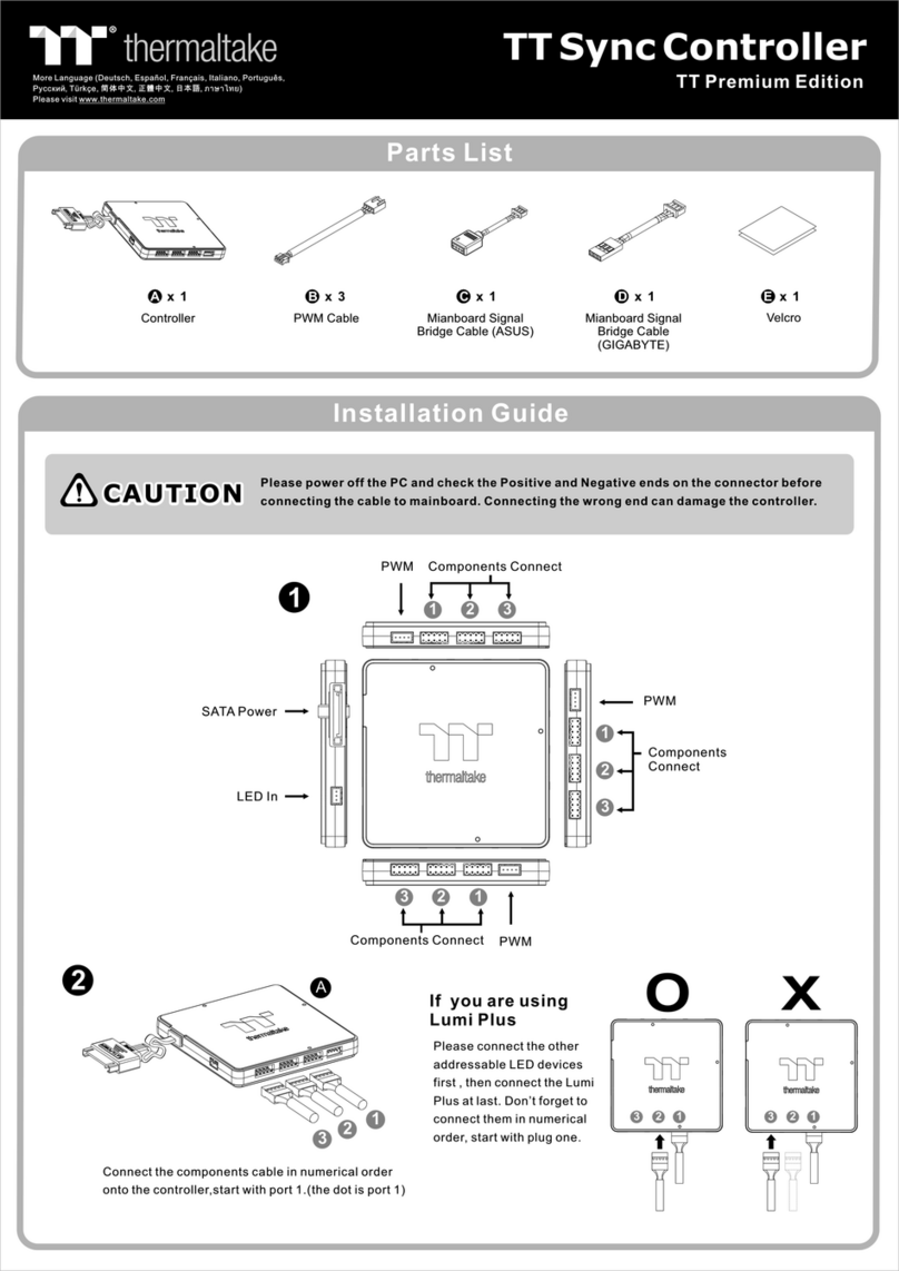
Controller
LED IN
LED OUT
NO.1 Controller
NO.2 Controller
1. Please power off the PC and check the Positive and
Negative ends on the connector before connecting
the cable to mainboard. Connecting the wrong end
can damage the controller.
2. Mainboard software can only control the LED color,
once Mainboard software is activated, LED color
function on the controller is disabled. The fan speed
is controlled by the controller.
CAUTIONCAUTION
1. Fa n Speed:
Switch over between 2 fan speed mo des
LED indicator shows Blue : No rma l mode
LED indicator shows Red : Low noise mo de
2. Light Mo de:
Switch over between 7 LED mo des.
Wave , Full Lighted, RG B Sp ectrum, Flow, Ri pple, Pulse, Blink
3. Color Mo de:
Whe n light mode is in Full Lighted, Ripple, Pu lse and Blink:
Switch over 7 LED colors . Red, Yellow, Gr een, Teal, Blue, Wh ite, Purple
Whe n light mode is in RG B Sp ectrum:
Click to me morize and lock the color you want, click again to unlock
the 256 colors auto rotation.
Whe n light mode is in Wave and Flow :
LED color can not be adjusted.
4. Light Speed:
Switch over between 4 light speed modes.
Slow, No rma l, Fast, Ex treme
If you want to control LED color
via mainboard software, you can
use the mianboard signal bridge
cable to connect the controllers.
If you want to connect two or more connectors,
you can use the LED signal bridge cable to
connect the controllers.
or
LED IN
E
F
G
Aura Addressable
Strip Header(s)
AOURS RGB Fusion
with Digital LEDs
ASUS GIGABYTE
EF
JRGB-strip Header(S)
MSI
E


