manuals.online logo
Brands
  1. Home
  2. •
  3. Brands
  4. •
  5. Thermaltake
  6. •
  7. Enclosure
  8. •
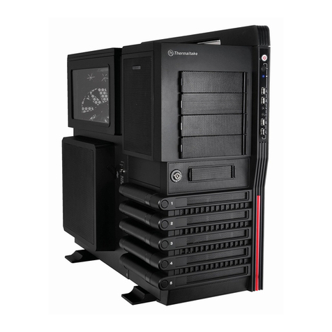
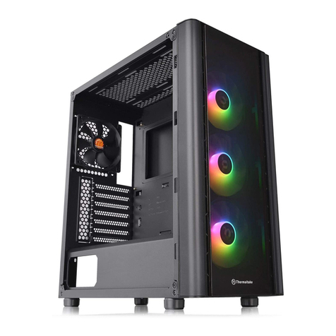
  9. Thermaltake V5 Black Edition VL70001W2Z User manual

Thermaltake V5 Black Edition VL70001W2Z User manual

лчиттничюнльтцию.
глтчн.Бзвыдны
www.sotmarket.ru
дбняинфмциятв,
тзывы,бзыиы
Инструкция
V5 Black Edition VL70001W2Z
Thermaltake
Перейти в карточку товара
8 800 775 98 98
2010 Thermaltake Technology Co., Ltd. All Rights Reserved. 2010.01
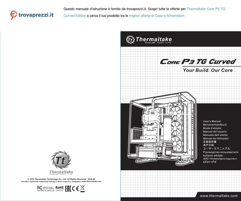
CAll other registered trademarks belong to their respective companies.www.thermaltake.comUser's ManualBenutzerhandbuchMode d󰾺emploiManual del usuarioManuale dell󰾺utente󴬪󷡾󷩋󵖯󵚙󶓉󵇗󵇬󴄫󲂇󲂝󲁗󲂝󲁛󲁿󲁬󲂆󲁃󲂌 kullanc elkitabTested To ComplyWith FCC StandardsFOR HOME OR OFFICE USEVL7000 Series
BlackEdition
5
Mobility at LAN Party
Chapter 1. Product IntroductionChapter 2. Installation GuideSpecificationChapter3 Leads InstallationCase LED connectionUSB connectionAudio Connection2.12.22.32.42.52.62.7Motherboard Installation3.5" & 5.25" Drives Installation3.5" HDD InstallationPCI Slot UsageFront Fan Installation (optional)PSU InstallationSide Panel Disassembly1.13.13.23.3020506070911121314-1814-1814-18Contents12SpecificationFigrureParts NameQ'tyUsed forAccessory- 5.25󰾾 Drive Bay- 3.5󰾾 Drive Bay- 3.5󰾾 Drive Bay (Hidden)- 2.5󰾾 Drive Bay (Hidden)9 or 61(converted from one 5.25󰾾 drive bay)- or 31(converted from one 5.25󰾾 drive bay)Transparent WindowSide PanelI/O PortsStandard PS2 Power Supply (Optional)PSU7.1 kg / 15.7 lbNet WeightMicro ATX , Standard ATX VL70001W2ZFront (Intake) : 120 x 120 x 25 mm (optional) x 1Rear (Exhaust) : 120 x 120 x 25 mm Turbo fan, 1300rpm, 17dBA x 1Top (Exhaust) : 200 x 200 x 20 mm Blue LED fan, 800 rpm, 14dBA x 1Side (Intake) : 120 x 120 x 25 mm (optional) x 1508.0 x 223.0 x 490.0 mm (20.0 x 8.78 x 19.3 inch)Exterior & Interior: BlackSECCMiddle TowerCase TypeExpansion SlotsMotherboardsColorMaterialDrive BaysCooling System Dimension(H*W*D)Model7eSATA x 1, USB2.0 x 2, MIC & Speaker (support AC󰾺97 & HD Audio) 6#32 satadoff M3 screw FDD ODD 6#32 hesagonL b racketbuzzer 6#32 screwwire s addlelock b racketbay c overspongefan b racket mother board3234132211111HDD m otherboardHDD m otherboard PCI bracket alarm arrange w ire side p late l ock 5.25" transfer 3 .5" driver bay 5.25" transfer 3 .5" cover sponge front fan bracket Chapter 4. OtherToughpower/ Purepower/ TR2 power supply series (optional)4.0191.21.30203AccessoryWarning and Notice
<170 mm<280 mm
CPU Cooler Height LimitationVGA (Add-on card) Length LimitationWaring!!- Height limit for the CPU heatsink: The height limit for the CPU heatsink is 170 mm (6.7 inches).- Length limit for the VGA (graphics card): The length limit for the VGA (graphics card) is 280 mm (11.0 inches).- If you󰾺re installing a top-front fan on the case, please do not install the first 5.25󰾾 bay device.Warnung!!- Höhenbeschränkung für CPU-Kühler: Die Höhenbeschränkung für den CPU-Kühler liegt bei 170 mm (6,7 Zoll).- Längenbeschränkung für die VGA (Grafikkarte): Die Längenbeschränkung für die VGA (Grafikkarte) beträgt 280 mm (11,0 Zoll).- Wenn Sie vorne oben im Gehäuse ein Gebläse anbringen, installieren Sie bitte nichts in den ersten 5,25 Zoll Schacht .Avertissement !- Hauteur limite du dissipateur thermique du processeur : La hauteur limite du dissipateur thermique du processeur est de 170 mm (6,7 pouces).- Longueur limite de la carte VGA (carte graphique) : La longueur limite de la carte VGA (carte graphique) est de 280 mm (11,0 pouces).- Si vous installez un ventilateur dans la partie supérieure avant du boîtier, veuillez ne pas installer de périphérique dans la première baie de 5,25 pouces.Precaución- Límite de altura para el disipador de calor de la CPU: El límite de altura para el disipador de calor de la CPU es de 170 mm (6,7 pulgadas).- Límite de longitud para la tarjeta gráfica (VGA): El límite de longitud para la tarjeta gráfica (VGA) en de 280 mm (11,0 pulgadas).- Si va a instalar un ventilador frontal superior en la carcasa, no instale el primer dispositivo de puerto de 5,25󰾾.Attenzione!- Limite di altezza per il dissipatore di calore della CPU: Il limite di altezza per il dissipatore di calore della CPU è 170 mm (6,7󰾺󰾺).- Limite di lunghezza per la VGA (schede grafiche): Il limite di lunghezza per la VGA (scheda grafica) è 280 mm (11,0󰾺󰾺).- In caso di installazione di una ventola anteriore superiore sul case, non installare primo dispositivo vano da 5,25󰾺󰾺.󷬇󴏫󾺢󾺢- CPU󵔄󶅒󴘉󶘥󸩹󴹇󸗱󴇗: CPU󵔄󶅒󴘉󶘥󸩹󴹇󸗱󴇗󶁛170mm ( 6.7󷊒󴎬 )󱾣- VGA(󸠐󶣛󴌂)󶘥󸔘󴹇󸗱󴇗: VGA(󸠐󶣛󴌂)󶘥󸔘󴹇󸗱󴇗󶁛280mm (11.0󷊒󴎬 )󱾣- 󴤣󴬪󷡾󵨀󶭒󳶫󸜃󴇮󵕚󸡉󵇨󾺭󷩬󴊠󴬪󷡾󶫍󳶡󵦞5.25󰾾󷡾󶼏󱾣󷬇󴏫󾺢󾺢- CPU󵔄󶂎󴘉󶘥󸩹󴹇󸗱󴇗󾺻 CPU󵔄󶂎󴘉󶘥󸩹󴹇󸗱󴇗󳷛170mm󾺩6.7󷊒󴮙󾺪󱾣- VGA󾺩󵗟󴌂󾺪󶘥󸔠󴹇󸗱󴇗󾺻 VGA󾺩󵗟󴌂󾺪󶘥󸔠󴹇󸗱󴇗󳷛280mm󾺩11.0󷊒󴮙󾺪󱾣- 󴤣󴬪󷡦󵛛󶭒󳶫󸜃󴇮󵕚󸡯󵇨󾺭󷮘󴊠󴬪󷡦󶫍󳶡󵍳󵦞5.25󰾾󷡦󶼏󱾣󷬇󴏫- CPU󲁳󲂝󲁩󲁘󲂔󲁐󲀏󸩹󱿶󴇗󸗱: CPU󲁳󲂝󲁩󲁘󲂔󲁐󲀏󸩹󱿶󴇗󸗱󲀐170 mm󲀈󱿺󱾣- VGA󾺩󲁑󲂊󲁶󲁄󲁤󲁐󲁚󲁌󲂝󲁪󾺪󲀏󸔘󱿶󴇗󸗱: VGA󾺩󲁑󲂊󲁶󲁄󲁤󲁐󲁚󲁌󲂝󲁪󾺪󲀏󸔘󱿶󴇗󸗱󲀐280 mm󲀈󱿺󱾣- 󲁒󲂝󲁚󲀌󲁩󲁤󲁸󲁶󲂎󲂔󲁩󲁶󲁂󲂔󲀳󴍷󲀫󳹹󱿲󲀬󴟕󴎩󱾢󵚡󴆾󲀏5.25󰾾󲁺󲁅󲁨󲁱󲁅󲁚󲀳󴍷󲀫󳹹󱿲󲀋󱿥󲀈󱿰󲀁󱿶󱿥󱾣!-      .        170  (6,7 ).-      VGA ( ).      VGA ( )  280  (11,0 ).-                5,25- .Uyar!!- CPU s alcs için yükseklik snr: CPU s alcs için yükseklik snr 170 mm󰾺dir (6,7 inç).- VGA (grafik kart) için uzunluk snr: VGA (grafik kart) için uzunluk snr 280 mm󰾺dir (11,0 inç).- Kasaya üst ön fan takyorsanz, lütfen ilk 5,25󰾾 bölmesine aygt takmayn.Warning and Notice34
56Side Panel DisassemblyEnglish /Unscrew thumbscrews and slide sidepanels off from the chassis.Deutsche /Lösen Sie die Flügelschrauben undschieben Sie die Seitentafeln vomGehäuse.Français /Dévissez les vis papillons et faites glisserles panneaux latéraux hors du châssis.Español /Desatornille los tornillos de mano y deslicelos paneles laterales para extraerlos delchasis.Italiano /Svitare le viti ad aletta e far scorrere ipannelli laterali fuori dallo chassis.Motherboard InstallationEnglish /1.Lay down the chassis.2.Install the motherboard in proper location and secure it with screws.Deutsche /1.Legen Sie das Gehäuse auf die Seite.2.Installieren Sie die Hauptplatine in ihrer vorgesehenen Position und sichern Sie sie mit Schrauben. Français /1.Posez à plat le châssis.2.Installez la carte mère dans l'endroit approprié et sécurisez-la avec des vis.Español /1. Tumbe el chasis.2. Instale la placa madre en la ubicación adecuada y asegúrela con tornillos.Italiano /1.Poggiare lo chassis.2.Installare la scheda madre nella posizione appropriata e fissarla con le viti.󶷢󸩵󳷎󵔨 /1. 󴮨󵨀󵭝󴸔󵓟󱾣2. 󴮨󳷜󵨀󵜠󵓟󶼏󴛉󴎩󸀊󶘥󳻮󶼏󳷇󶓉󸚗󳺗󴊦󳷎󳷬󷝛󶴓󴚛󴬻󱾣󵖆󵛍󷨿 /1.󲁘󲂄󲂝󲁘󲀳󳶬󲀌󶼏󱿮󲀟󱿺󱾣2.󲁿󲁗󲂝󲁽󲂝󲁪󲀳󸀊󴆨󲀋󴟕󵇡󲀌󴍷󲀫󳹹󱿲󱾢󲀎󱿹󲀈󴚛󴬻󱿸󲀟󱿺󱾣 /1.   . 2.          .󶬡󳻴󳷎󵔨 /1. 󵓟󴸔󵛛󶭒󱾣2. 󴛉󴎩󷾣󶘥󳻮󶼏󴬪󷡦󳷜󵜠󴸗󳺆󷝛󳶾󴬪󴄉󴚛󴬻󱾣Türkçe /1.Kasay yan yatrn.2.Ana kart uygun konuma takn ve vidalarla sabitleyin.󶷢󸩵󳷎󵔨 /󶦜󸘅󵨀󵭝󴼭󵕚󴙼󸟧󵉨󵊨󷝛󶴓󶃗󴼭󴮨󴀕󶇩󴎲󴼭󵹲󴉶󶦜󸔬󶬡󳻴󳷎󵔨 /󶦜󸘅󵛛󶭒󴎯󵕚󴙼󸠸󵉨󵊨󷝛󳶾󶃗󴎯󴮧󳽈󶇩󴎲󴎯󵹲󴉉󶦜󴺡󵖆󵛍󷨿 /󷜗󲀎󱿹󲀳󵈽󱿥󲀇󱾢󲁖󲁅󲁪󲁲󲁮󲂌󲀳󲁘󲂄󲂝󲁘󱿬󲀪󲁚󲂊󲁅󲁪󱿶󱿼󲀋󱿭󲀪󴆛󱿸󲀟󱿺󱾣 /         .Türkçe /Elle sklan vidalar gevetin ve yan panellerikaydrarak kasadan çkarn.
783.5"& 5.25󰾾 Drives InstallationEnglish /1. Remove the front panel and 5.25󰾾 driver bay mesh cover2. Turn the lock device counterclockwiseto unlock and remove the lock device.3. Insert the hardware and attach thelock device to the hardware in place.4. Turn the lock device clockwise to lockthe device.Deutsche /1. Entfernen Sie die Tafel auf der Vorderseite und die 5,25󰾾 Schacht Netzabdeckung2. Drehen Sie die Verriegelung gegen den Uhrzeigersinn, um sie zu öffnen und zu entfernen.3. Schieben Sie die Hardware hinein und bringen Sie die Verriegelung zur Fixierung der Hardware an.4. Drehen Sie die Verriegelung im Uhrzeigersinn, um sie zu schließen.Français /1. Retirez le panneau avant et le couvercle grillagé de la baie de lecteur de 5,25".2. Tournez le verrou dans le sens contraire des aiguilles d'une montre pour déverrouiller et retirez le verrou.3. Insérez le lecteur et mettez le verrou sur le lecteur qui est en place.4. Tournez le verrou dans le sens des aiguilles d'une montre pour verrouillerEspañol /1. Extraiga el panel frontal y la cubierta de malla de la bahía de unidad de 5,25 pulgadas.2. Gire el dispositivo de cierre en el sentido contrario a las agujas del reloj para desbloquearlo y extraerlo.3. Inserte el hardware y acople el dispositivo de cierre al hardware ubicado en su lugar.4. Gire el dispositivo de cierre en el sentido de las agujas del reloj para cerrarlo.Italiano /1. Rimuovere il pannello anteriore e la rete di copertura del vano unità da 5,25󰾺󰾺2. Ruotare il dispositivo di blocco in seno antiorario per sbloccare e rimuovere tale dispositivo.3. Inserire il disco rigido e fissare il dispositivo di blocco in posizione.4. Ruotare il dispositivo di blocco in senso orario per chiudere il dispositivo.󶷢󸩵󳷎󵔨 /1. 󶦜󸘅󵨀󵭝󴇮󸜃󶇩󷆨5.25󰾾󵨵󵜠2. 󳼾󷾧󵗣󸎹󵕚󴎲󷻪󴉶󴮨5.25󰾾󶃂󷝛󶴓󵈄󴄘󴍷󳶬3. 󵍳󴄆󶠍󸩵󷡾󶼏󳷇󷡾󳶫󵈄󴄘4. 󳼾󶄈󸞧󵗣󸅾󵕚󴎲󴮨󶃂󷝛󶴓󵈄󴄘󷡾󳶫󳷇󴚛󴬻󶬡󳻴󳷎󵔨 /1. 󶦜󸘅󵛛󶭒󴇮󸜃󶇩󳶯5.25󰾾󵨵󵜠2. 󳼾󷾧󵖗󸑀󵕚󴎲󷼍󴉉󴮧5.25󰾾󵖁󷝛󳶾󵈄󴄘󴍷󳶬3. 󵍳󴄆󶠍󳺗󷡦󶼏󴸗󷡦󳶫󵈄󴄘4. 󳼾󶄈󸠛󵖗󸐩󵕚󴎲󴮧󵖁󷝛󳶾󵈄󴄘󷡦󳶫󴸗󴚛󴬻󵖆󵛍󷨿 /1. 󴇮󸜃󲁲󲁮󲂌󲀉5.25󰾾󲁪󲂊󲁅󲁱󲁺󲁅󲀏󲂂󲁤󲁘󲂆󲁌󲁱󲂝󲀳󴍷󲀫󴢷󱿸󲀟󱿺2. 󲂎󲁤󲁐󲁨󲁱󲁅󲁚󲀳󴍮󵗣󷦩󵕚󴎲󲀌󴙿󱿸󲀇󲂎󲁤󲁐󷦄󸘅󱿸󱾢󴍷󲀫󴢷󱿸󲀟󱿺󱾣3. 󲁰󲂝󲁪󲁇󲁈󲁃󲀳󵋠󴄆󱿸󱾢󲂎󲁤󲁐󲁨󲁱󲁅󲁚󲀳󲁰󲂝󲁪󲁇󲁈󲁃󲀏󵇡󴬻󲀏󳻮󶼏󲀌󲂎󲁤󲁐󱿸󲀟󱿺󱾣4. 󲂎󲁤󲁐󲁨󲁱󲁅󲁚󲀳󵗣󷦩󵕚󴎲󲀌󴙿󱿸󲀇󲁨󲁱󲁅󲁚󲀳󲂎󲁤󲁐󱿸󲀟󱿺󱾣 /1.         5,25- .2.      ,     .3.        .4.         .Türkçe /1. Ön panoyu ve 5,25󰾾 sürücü bölmesi geçmeli kapan çkarn2. Kilidini açmak için, kilit parçasn saatin ters yönünde döndürün ve kilidi açldktan sonra çkarn.3. Donanm yerletirin ve kilit parçasn, donanm üzerindeki yerine yerletirin.4. Kilitleme parçasn saat yönünde döndürerek aygt kilitleyin.
English /1. Remove the front panel and 5.25󰾾 driver bay mesh cover2. Turn the lock device counterclockwise to unlock and remove the lock device. 3. Insert the hardware and attach the lock device to the hardware in place.4. Insert the HDD cage back into the drive bays5. Turn the lock device clockwise to lock.Deutsche /1. Entfernen Sie die Tafel auf der Vorderseite und die 5,25󰾾 Schacht Netzabdeckung2. Drehen Sie die Verriegelung gegen den Uhrzeigersinn, um sie zu öffnen und zu entfernen.3. Schieben Sie die Hardware hinein und bringen Sie die Verriegelung zur Fixierung der Hardware an.4. Bringen Sie den HDD-Käfig in die Drive Bays ein5. Drehen Sie die Verriegelung im Uhrzeigersinn, um sie zu schließen.Français /1. Retirez le panneau avant et le couvercle grillagé de la baie de lecteur de 5,25".2. Tournez le verrou dans le sens contraire des aiguilles d'une montre pour déverrouiller et retirez le verrou.3. Insérez le lecteur et mettez le verrou sur le lecteur qui est en place.4. Réinsérez la cage de disques durs dans les baies de lecteur.5. Tournez le verrou dans le sens des aiguilles d'une montre pour verrouiller.Español /1. Extraiga el panel frontal y la cubierta de malla de la bahía de unidad de 5,25 pulgadas.2. Gire el dispositivo de cierre en el sentido contrario a las agujas del reloj para desbloquearlo y extraerlo.3. Inserte el hardware y acople el dispositivo de cierre al hardware ubicado en su lugar.4. Inserte el cajón del HDD en las bahías de unidad. 5. Gire el dispositivo de cierre en el sentido de las agujas del reloj para cerrar.Italiano /1. Rimuovere il pannello anteriore e la rete di copertura del vano unità da 5,25󰾺󰾺2. Ruotare il dispositivo di blocco in seno antiorario per sbloccare e rimuovere tale dispositivo.3. Inserire il disco rigido e fissare il dispositivo di blocco in posizione.4. Inserire l󰾺alloggio HDD nella parte posteriore nei vani unità5. Ruotare il dispositivo di blocco in senso orario per chiudere.󶷢󸩵󳷎󵔨 /1. 󶦜󸘅󵨀󵭝󴇮󸜃󶇩󷆨5.25󰾾󵨵󵜠2. 󳼾󷾧󵗣󸎹󵕚󴎲󷻪󴉶󴮨󶃂󷝛󶴓󵈄󴄘󴍷󳶬3. 󵍳󴄆󶠍󸩵󷡾󶼏󳷇󷡾󳶫󶃂󷝛󶴓󵈄󴄘4. 󴮨󶠍󶡀󵓐󵝗󵍳󴙿5.25󰾾󷡾󶼏󳷎5. 󳼾󶄈󸞧󵗣󸅾󵕚󴎲󴮨󶃂󷝛󶴓󵈄󴄘󷡾󳶫󳷇󴚛󴬻󶬡󳻴󳷎󵔨 /1. 󶦜󸘅󵛛󶭒󴇮󸜃󶇩󳶯5.25󰾾󵨵󵜠2. 󳼾󷾧󵖗󸑀󵕚󴎲󷼍󴉉󴮧󵖁󷝛󳶾󵈄󴄘󴍷󳶬3. 󵍳󴄆󶠍󳺗󷡦󶼏󴸗󷡦󳶫󵖁󷝛󳶾󵈄󴄘4. 󴮧󶠍󶙹󵓐󵝗󵍳󴙿5.25󰾾󷡦󶼏󳷎5. 󳼾󶄈󸠛󵖗󸐩󵕚󴎲󴮧󵖁󷝛󳶾󵈄󴄘󷡦󳶫󴸗󴚛󴬻󵖆󵛍󷨿 /1. 󴇮󸜃󲁲󲁮󲂌󲀉5.25󰾾󲁪󲂊󲁅󲁱󲁺󲁅󲀏󲂂󲁤󲁘󲂆󲁌󲁱󲂝󲀳󴍷󲀫󴢷󱿸󲀟󱿺2. 󲂎󲁤󲁐󲁨󲁱󲁅󲁚󲀳󴍮󵗣󷦩󵕚󴎲󲀌󴙿󱿸󲀇󲂎󲁤󲁐󷦄󸘅󱿸󱾢󴍷󲀫󴢷󱿸󲀟󱿺󱾣3. 󲁰󲂝󲁪󲁇󲁈󲁃󲀳󵋠󴄆󱿸󱾢󲂎󲁤󲁐󲁨󲁱󲁅󲁚󲀳󲁰󲂝󲁪󲁇󲁈󲁃󲀏󵇡󴬻󲀏󳻮󶼏󲀌󲂎󲁤󲁐󱿸󲀟󱿺󱾣4. HDD󲁒󲂝󲁙󲀳󲁪󲂊󲁅󲁷󲁺󲁅󲀌󵇜󱿸󲀟󱿺5. 󲂎󲁤󲁐󲁨󲁱󲁅󲁚󲀳󵗣󷦩󵕚󴎲󲀌󴙿󱿸󲀇󲂎󲁤󲁐󱿸󲀟󱿺󱾣3 .5" HDD Installation9 /1.         5,25- .2.      ,     .3.        .4.         .5.        .Türkçe /1. Ön panoyu ve 5,25󰾾 sürücü bölmesi geçmeli kapan çkarn2. Kilidini açmak için, kilit parçasn saatin ters yönünde döndürün ve kilidi açldktan sonra çkarn.3. Donanm yerletirin ve kilit parçasn, donanm üzerindeki yerine yerletirin.4. HDD kafesini, sürücü bölmelerine geri yerletirin5. Kilit parçasn, kilitlemek için saat yönünde döndürün.23343510
PCI Slot UsageFront Fan Installation (optional)English /1. Pull open the holder.2. Remove the PCI bracket.3. Insert the PCI card into the PCI slot.4. Push to fasten the holder.Deutsche /1. Ziehen Sie den Halter auf.2. Entfernen Sie die PCI-Klammer.3. Stecken Sie die PCI Karte in den PCI Steckplatz.4. Drücken Sie den Halter ein, um ihn zu sichern.Français /1. Tirez pour ouvrir le support.2. Enlevez le slot PCI.3. Insérez la carte PCI dans le slot PCI.4. Poussez pour fixer le support.Español /1. Tire para abrir el sostenedor.2. Extraiga el soporte del PCI.3. Inserte la tarjeta del PCI en la ranura para el PCI.4. Empuje para sujetar el sostenedor.Italiano /1. Tirare per aprire l'alloggiamento.2. Rimuovere il supporto PCI.3. Inserire la scheda PCI nello slot PCI.4. Premere per fissare l'alloggiamento.English /1. Pull the front panel to detach it from the case.2. Remove the HDD cage fan slot then screw the fan on fan slot.3. Install the fan in proper location and secure it with screws. Deutsche /1. Ziehen Sie an der Frontabdeckung, um sie vom Gehäuse zu entfernen.2. Entfernen den HDD-Käfig Gebläseschlitz, dann schrauben Sie das Gebläse am Gebläseschlitz fest.3. Installieren Sie den Ventilator an der vorgesehenen Position und sichern Sie ihn mit Schrauben. Français /1. Tirez sur le panneau avant pour le séparer du boîtier.2. Enlevez le logement pour ventilateur de la cage de disques durs, puis vissez le ventilateur dans le logement.3. Installez le ventilateur dans l󰾺endroit approprié et fixez-le avec des vis. Español /1. Tire del panel frontal para separarlo de la caja.2. Retire la ranura del ventilador del cajón del HDD y atornille el ventilador en la ranura del ventilador.3. Instale el ventilador en la ubicación adecuada y asegúrelo con tornillos. 󶷢󸩵󳷎󵔨 /1. 󶦜󴉶PCI󶃂󷝛󶴓󵨀󵥬󳺆󸪧󸔬󴚛󴬻󵈄󴄘2. 󶦜󸘅PCI󵨵󶇨3. 󵍳󴄆PCI󷡾󶼏󵕝PCI󵍳󵦞󳷎4. 󴎲󳶬󴡴󴄆PCI󵈄󴄘󳷇󴚛󴬻PCI󷡾󶼏󶬡󳻴󳷎󵔨 /1. 󶦜󴉉PCI󵖁󷝛󳶾󵛛󵜥󳺆󵜟󴺡󴚛󴬻󵈄󴄘2. 󶦜󸘅PCI󵨵󶇨3. 󵍳󴄆PCI󷡦󶼏󳸯PCI󵍳󵦞󳷎4. 󴎲󳶬󴌬󴄆PCI󵈄󴄘󴸗󴚛󴬻PCI󷡦󶼏󵖆󵛍󷨿 /1. 󲁼󲂌󲁡󲂝󲀳󴺶󲀄󴻖󲀄󲀇󸔬󱿲󲀟󱿺󱾣2. PCI󲁷󲂊󲁒󲁤󲁩󲀳󴍷󲀫󴢷󱿸󲀟󱿺󱾣3. PCI󲁌󲂝󲁪󲀳PCI󲁚󲂎󲁤󲁩󲀌󵋠󴄆󱿸󲀟󱿺4. 󲁼󲂌󲁡󲂝󲀳󵉝󱿸󲀇󶶁󲀢󳹹󱿲󲀟󱿺󱾣 /1.     .2.   PCI.3.   PCI   PCI.4. ,   .Türkçe /1. Tutucuyu çekerek açn.2. PCI plakasn çkarn.3. PCI kartn PCI yuvasna yerletirin.4. Tutucuyu iterek sabitleyin.1233Italiano /1. Tirare il pannello anteriore per staccarlo dal case.2. Rimuovere lo slot della ventola dell'alloggio HDD, quindi avvitare la ventola sull'apposito slot.3. Installare la ventola nella posizione corretta e fissarla con le viti. 󶷢󸩵󳷎󵔨 /1. 󶦜󸘅󵨀󵭝󴇮󸜃󶇩2. 󴍷󳶬󶠍󶡀󶡢󵝗󴇮󵕚󵑬󶇨󳷇󴮨󸡉󵇨󸌷󴛉󵑬󶇨󳶫3. 󴮨󸡉󵇨󴬪󷡾󴛉󵬄󶡛󳻮󶼏󳷇󶓉󷝛󶴓󸌷󳶫󶬡󳻴󳷎󵔨 /1. 󶦜󸘅󵛛󴢔󴇮󸜃󶇩2. 󴍷󳶬󶠍󶙹󶡢󵝗󴇮󵕚󵋂󶇨󴸗󴮧󸡯󵇨󸒢󴛉󵋂󶇨󳶫3. 󴮧󸡯󵇨󴬪󷡦󴛉󵬄󶠏󳻮󶼏󴸗󶓉󷝛󳶾󸒢󳶫󵖆󵛍󷨿 /1. 󴇮󸜃󲁲󲁮󲂌󲀳󴺶󲀄󴻖󲀄󲀇󱾢󲁒󲂝󲁚󱿬󲀪󴍷󲀫󴢷󱿸󲀟󱿺󱾣2. HDD󲁒󲂝󲁙󲀏󲁶󲁂󲂔󲁚󲂎󲁤󲁩󲀳󴍷󲀫󴢷󱿸󲀇󱿬󲀪󱾢󲁶󲁂󲂔󲁚󲂎󲁤󲁩󲀌󲁶󲁂󲂔󲀳󲀎󱿹󲀈󶓺󲀢󲀇󱿰󲀁󱿶󱿥󱾣3. 󲁶󲁂󲂔󲀳󸀊󴆨󲀋󴟕󵇡󲀌󴍷󲀫󳹹󱿲󱾢󲀎󱿹󲀈󴚛󴬻󱿸󲀟󱿺󱾣  /1.     ,     .2.               .3.         . Türkçe /1. Ön panoyu çekerek kasadan ayrn.2. HDD kafesi fan yuvasn çkarn ve daha sonra fan, fan yuvasnn üzerine vidalayn.3. Fan, uygun bir konuma takn ve vidalarla sabitleyin. 11
English /Place the power supply in proper location and secure it with screws.Deutsche /Installieren Sie das Netzteil an seiner Position und sichern Sie es mit Schrauben. Français /Mettez l'alimentation dans le bon endroit et sécurisez-la avec des vis.Español /Coloque el suministro de alimentación en el lugar adecuado y asegúrelo con tornillos. Italiano /Posizionare l'alimentatore in modo appropriato e fissarlo utilizzando le viti.󶬡󳻴󳷎󵔨 /󵀑󴻴󴬻󳻮󶓖󵸱󳼼󴸵󴘉󳻮󶼏󴸗󳺆󷝛󳶾󴬪󴄉󴚛󴬻󱾣󵖆󵛍󷨿 /󸚜󵸱󷡦󶼏󲀳󸀊󴆨󲀋󴟕󵇡󲀌󴍷󲀫󳹹󱿲󱾢󲀎󱿹󲀈󴚛󴬻󱿸󲀟󱿺󱾣 /         .󶷢󸩵󳷎󵔨 /󴮨󸚜󵸱󳼼󵅪󴘉󵓟󴛉󵬄󶡛󶘥󳻮󶼏󾺭󳷇󶓉󷝛󶴓󴚛󴬻󸌷󳶫Türkçe /Güç kaynan uygun konuma yerletirin ve vidalarla sabitleyin.PSU Installation1413Leads InstallationLeads Installation GuideCase LED Connection / On the front of the case, you can find some LEDs and switch leads. Please consult your user manual of your motherboard manufacturer, then connect these leads to the panel header on the motherboard.USB Connection / Please consult your motherboard manual to find out the section of 󰾽USB connection󰾾.Audio Connection / Please refer to the following illustration of Audio connector and your motherboard user manual. Please select the motherboard which used AC󰾺97 or HD Audio(Azalia),(be aware of that your audio supports AC󰾺97 or HD Audio (Azalia)) or it will damage your device(s).EnglishDeutscheAnschlüsse herstellenGehäuse-LED-Verbindungen / Auf der Gehäusevorderseite finden Sie einige LEDs und Verbindungen. Bitte nehmen Sie die Gebrauchsanweisung Ihres Motherboard Herstellers zur Hilfe und schließen Sie diese Verbindungen an die Panel Header Belegung des Motherboards an.USB Anschluss / Bitte nehmen Sie die Gebrauchsanweisung Ihres Motherboards zur Hilfe und lesen Sie unter dem Kapitel 󰾿USB Anschlüsse󰾽 nach.Audio Anschlüsse / Bitte beachten Sie die folgende Abbildung der Audio Anschlüsse und die Anweisung in der Gebrauchsanweisung Ihres Motherboards. Bitte wählen Sie das Motherboard, das AC󰾺97 oder HD Audio(Azalia) verwendet, (achten Sie darauf, dass Ihr Audio AC󰾺97 bzw. HD Audio (Azalia unterstützt)). Andernfalls entstehen schwere Schäden an Ihrem(n) Gerät(en)!!!MIC_INFP_OUT_RMIC_BIASNCFP_RET_LFP_OUT_LNCFP_RET_RAUD_GNDKEY24683751910The Pin of AC󰾺97 AudioCable Assigment VCC2 RED D2+ GREEND2-Y ELLOW GND2B LACK 9 KEY D1- B LUED1+P URPLEVCC1O RANGEGND1 B ROWN24683751The Pin of USB Cable AssigmentNC10PORT1_LPORT2_RPORT1_RSENSE-SENDSENSE2-RETURNPORT2LPRESENCE#SENSE1-RETURNGNDKEY24683751910HD Audio
1615Guide d'installation des filsConnexion des voyants du boîtier / Sur la face avant du boîtier, vous trouverez plusieurs voyants et les fils des boutons. S'il vous plaît consultez le guide d'utilisateur du fabricant de votre carte mère, puis connectez ces fils aux connecteurs sur la carte mère.Connexion USB / S'il vous plaît consultez le manuel de votre carte mère à la section "Connexion USB" Connexion Audio / S'il vous plaît référez vous à l'illustration suivante du connecteur audio et au guide de l'utilisateur de votre carte mère. S'il vous plaît sélectionnez une carte mère supportant AC'97 ou HD Audi (Azalia), (faites attention que votre audio supporte l'AC'97 ou HD Audio (Azalia)) sinon cela pourrait endommager votre matériel.FrançaisEspañolGuía de Instalación de CablesConexión del LED de la caja / En la parte frontal de la caja, encontrará algunos LED y cables de interruptores. Consulte el manual del usuario del fabricante de la placa madre, a continuación conecte estos cables al conector de la placa madre.Conexión USB / Consulte el manual de la placa madre para obtener más información sobre el apartado 󰾽Conexión USB"Conexión de Audio / Consulte la siguiente ilustración del conector de Audio y el manual del usuario de la placa madre.Seleccione la placa madre que utiliza AC󰾺97 o HD Audio (Azalia), (asegúrese de que su audio admite AC󰾺97 o HD Audio (Azalia)) si no, sus dispositivos resultarán dañadosItaliano󶷢󸩵󳷎󵔨Guida di installazione dei contattiConnessione del LED del case / Nella parte anteriore del case, sono presenti alcuni contatti per interruttori e LED. Consultare il manuale utente del produttore della scheda madre, quindi connettere i contatti alla parte superiore del pannello sulla scheda madre.Connessione USB / Consultare il manuale per la scheda madre che comprende la sezione relative alla 󰾽connessione USB󰾾.Connessione Audio / Fare riferimento all󰾺illustrazione riportata di seguito del connettore Audio e al manuale utente per la scheda madre.Selezionare la scheda madre relativa a AC󰾺97 o HD Audio (Azalia) e considerare che il supporto audio è compatibile con AC󰾺97 o HD Audio (Azalia); in caso contrario, le periferiche potrebbero venire danneggiate.󶵻󵛱󴬪󷡾󷩋󵖯󵨀󵭝LED󷿄󵍆󵕚󴺰 / 󴛉󵨀󵭝󴇮󵕚󶘥󸜃󵜠󴼭󸜃󾺭󴎐󳺆󵈟󴇑󳶡󳸼LED󷆨󸔬󸕽󶵻󵛱󾺩POWER Switch󰿇.󾺪󾺭󷩬󴍤󶾤󳷜󵨀󵜠󳼠󶓉󷩋󵖯󵚙󾺭󳷇󴮨󵨀󵭝󳶫󶘥󶵻󵛱󵬄󶡛󴛑󷿄󵍆󴇑󳷜󵨀󵜠󳶫󾺭󷾺󳸼󶵻󵛱󷾻󴷙󸂞󵚤󴌑󵚪󵦺󶰅󴛉󳶫󸜃󾺭󴤣󵜽󵰳󵚪󶘥󷨒󾺭󷩬󵈟󴆛󵨀󵭝󴇮󵕚󸜃󵜠󳶫󶵻󵛱󴍀󵛍󶘥󳻮󶼏󳺆󶞆󷿴󵬄󶡛󶘥󳼧󵸱󱾣 USB 󷿄󵍆 / 󷩬󴍤󶾤󳷜󵨀󵜠󳼠󶓉󵇬󴄫󵈟󴆛󳷜󵨀󵜠󳶫󶘥USB󷿄󵍆󴫵󳻮󸞔󵓩󷿄󵍆 / 󷩬󵟚󵑻󳶬󸜃󶘥󸞔󵸱󵍆󸟎󴚷󶣛󷆨󳷜󵨀󵜠󳼠󶓉󵇬󴄫󳼧󷿄󵍆󸞔󵓩󷡾󶼏󾺭󷩬󶡛󷨮󳷜󵨀󵜠󳶫󶘥󸞔󵓩󷡾󶼏󵗐󵓐󵎕AC' 97󸞔󵓩󵆷󵗐HD󸞔󵓩(Azalia)󾺭󷡾󶼏󸋐󷩅󴎐󷂞󵚤󴮯󷆕󳷜󵨀󵜠󸞔󵓩󷡾󶼏󶘥󵭡󵎮󾺭󵝱󳸼󳷜󵨀󵜠󶘥󸞔󵓩󷡾󶼏󳶮󵚤󷆨󳶬󵕚󶘥󴚷󶣛󴬭󴄉󶚙󴎭󾺭󷩬󴍤󸃭󳷜󵨀󵜠󳼠󶓉󵇬󴄫󳺆󴼸󴇑󵬄󶡛󶘥󴬪󷡾󷱨󷦫MIC_INMIC_INFP_OUT_RFP_OUT_RMIC_BIASMIC_BIASNCNCFP_RET_LFP_RET_LFP_OUT_LFP_OUT_LNCNCFP_RET_RFP_RET_RAUD_GNDAUD_GNDKEYKEY2244668833775511991010The Pin of AC󰾺97 AudioCable AssigmentThe Pin of AC󰾺97 AudioCable Assigment VCC2 RED VCC2 RED D2+ GREEN D2+ GREEND2-Y ELLOW D2-Y ELLOW GND2B LACK GND2B LACK 9 9 KEY KEY D1- B LUED1- B LUED1+P URPLED1+P URPLEVCC1O RANGEVCC1O RANGEGND1 B ROWNGND1 B ROWN2244668833775511The Pin of USB Cable AssigmentThe Pin of USB Cable AssigmentNCNC1010PORT1_LPORT1_LPORT2_RPORT2_RPORT1_RPORT1_RSENSE-SENDSENSE-SENDSENSE2-RETURNSENSE2-RETURNPORT2LPORT2LPRESENCE#PRESENCE#SENSE1-RETURNSENSE1-RETURNGNDGNDKEYKEY2244668833775511991010HD AudioHD Audio
1817󶬡󳻴󳷎󵔨󵖆󵛍󷨿󲂋󲂝󲁪󶵻󲀏󴍷󲀫󳹹󱿲󲁍󲁅󲁪󲁒󲂝󲁚 LED 󲀏󵍆󶴻USB 󲀏󵍆󶴻󲁋󲂝󲁨󲁄󲁋󵍆󶴻󲂋󲂝󲁪󶵻󲀏󴍷󲀫󳹹󱿲󲁍󲁅󲁪 / 󲁒󲂝󲁚󴇮󸜃󲀌󲀐󱾢LED󲀉󲁚󲁅󲁤󲁢󲂋󲂝󲁪󶵻󱿭󱿣󲀫󲀟󱿺󱾣 󲁿󲁗󲂝󲁽󲂝󲁪󲂂󲂝󲁌󲂝󲀏󲂇󲂝󲁗󲂝󲁿󲁬󲂆󲁃󲂌󲀳󴍣󶄈󱿸󱾢󱿴󲀭󲀪󲀏󲂋󲂝󲁪󶵻󲀳󲁿󲁗󲂝󲁽󲂝󲁪󲀏󲁲󲁮󲂌󲁹󲁤󲁡󲀌󵍆󶴻󱿸󲀇󱿰󲀁󱿶󱿥󱾣USB 󲀏󵍆󶴻 / 󲁿󲁗󲂝󲁽󲂝󲁪󲀏󲁿󲁬󲂆󲁃󲂌󲀳󴍣󶄈󱿸󲀇󱾢󱾭USB󵍆󶴻󱾮󲀏󲁜󲁐󲁘󲂈󲂔󲀳󵍃󱿸󲀟󱿺󱾣󲁋󲂝󲁨󲁄󲁋󵍆󶴻 / 󲁋󲂝󲁨󲁄󲁋󲁔󲁮󲁐󲁠󲀏󵫂󲀏󴚔󲀉󲁿󲁗󲂝󲁽󲂝󲁪󲀏󲂇󲂝󲁗󲂝󲁿󲁬󲂆󲁃󲂌󲀳󴍣󶄈󱿸󲀇󱿰󲀁󱿶󱿥󱾣AC󰾺97󲀟󲀀󲀐HD󲁋󲂝󲁨󲁄󲁋(Azalia)󲀳󳼠󶓉󱿺󲀬󲁿󲁗󲂝󲁽󲂝󲁪󲀳󸀙󵈿󱿸󲀇󱿰󲀁󱿶󱿥(󲁋󲂝󲁨󲁄󲁋󱿭AC󰾺97󲀟󲀀󲀐HD󲁋󲂝󲁨󲁄󲁋(Azalia)󲀳󲁖󲁾󲂝󲁩󱿸󲀇󱿥󲀬󱿴󲀉󲀳󶡛󷨮󱿸󲀇󱿰󲀁󱿶󱿥)󱾣󲁖󲁾󲂝󲁩󱿸󲀇󱿥󲀋󱿥󲀉󱾢󲁨󲁱󲁅󲁚󱿭󵎮󴁘󱿸󲀟󱿺)󱾣󲁒󲂝󲁚 LED 󲀏󵍆󶴻󵛛󴢔LED󷽿󵍆󵕚󴺰USB 󷽿󵍆󸞔󵓩󷽿󵍆󶹠󵛱󴬪󷡦󷮕󵖯 / 󴛉󵛛󴢔󴇮󵕚󶘥󸜃󵜠󴎯󸜃󾺭󴎐󳺆󵈟󴇑󳶡󳸼LED󳶯󴺡󴄔󶹠󵛱󾺩POWER Switch󰿇.󾺪󾺭󷮘󴍣󶾤󳷜󵜠󳼠󶓉󷮕󵖯󳸇󾺭󴸗󴮧󵛛󴢔󳶫󶘥󶹠󵛱󵬄󶠏󴛑󷽿󵍆󴇑󳷜󵜠󳶫󾺭󷽺󳸼󶹠󵛱󷾻󴷙󸂞󳺻󴌑󵚪󵞨󶬟󴛉󳶫󸜃󾺭󴤣󵜽󵱂󵚪󶘥󷭾󾺭󷮘󵈟󴆛󵛛󴢔󴇮󵕚󸜃󵜠󳶫󶹠󵛱󴍀󵛍󶘥󳻮󶼏󳺆󶞆󷿴󵬄󶠏󶘥󵜆󵸱󱾣 USB 󷽿󵍆 / 󷮘󴍣󶾤󳷜󵜠󳼠󶓉󵇬󴄭󵈟󴆛󳷜󵜠󳶫󶘥USB󷽿󵍆󴫵󳻮󸞔󵓩󷽿󵍆 / 󷮘󵟚󵌏󳶬󸜃󶘥󸞔󵸱󵍆󴣕󴚟󶣛󳶯󳷜󵜠󳼠󶓉󵇬󴄭󵜆󷽿󵍆󸞔󵓩󷡦󶼏󾺭󷮘󶠏󷭅󳷜󵜠󳶫󶘥󸞔󵓩󷡦󶼏󵗐󵓐󵊢AC' 97󸞔󵓩󵆷󵗐HD󸞔󵓩(Azalia)󾺭󷡦󶼏󸒺󷮐󴎐󷂞󳺻󴮝󷆕󳷜󵜠󸞔󵓩󷡦󶼏󶘥󵭢󵌀󾺭󵝱󳸼󳷜󵜠󶘥󸞔󵓩󷡦󶼏󳶮󳺻󳶯󳶬󵕚󶘥󴚟󵞨󴬭󴄉󶚙󴎭󾺭󷮘󴍣󸃭󳷜󵜠󳼠󶓉󵇬󴄭󳺆󴼸󴇑󵬄󶠏󶘥󴬪󷡦󳾂󵀐󶹠󵛱󴬪󷡦󷮕󵖯 / 󴛉󵛛󴢔󴇮󵕚󶘥󸜃󵜠󴎯󸜃󾺭󴎐󳺆󵈟󴇑󳶡󳸼LED󳶯󴺡󴄔󶹠󵛱󾺩POWER Switch󰿇.󾺪󾺭󷮘󴍣󶾤󳷜󵜠󳼠󶓉󷮕󵖯󳸇󾺭󴸗󴮧󵛛󴢔󳶫󶘥󶹠󵛱󵬄󶠏󴛑󷽿󵍆󴇑󳷜󵜠󳶫󾺭󷽺󳸼󶹠󵛱󷾻󴷙󸂞󳺻󴌑󵚪󵞨󶬟󴛉󳶫󸜃󾺭󴤣󵜽󵱂󵚪󶘥󷭾󾺭󷮘󵈟󴆛󵛛󴢔󴇮󵕚󸜃󵜠󳶫󶹠󵛱󴍀󵛍󶘥󳻮󶼏󳺆󶞆󷿴󵬄󶠏󶘥󵜆󵸱󱾣 USB 󷽿󵍆 / 󷮘󴍣󶾤󳷜󵜠󳼠󶓉󵇬󴄭󵈟󴆛󳷜󵜠󳶫󶘥USB󷽿󵍆󴫵󳻮󸞔󵓩󷽿󵍆 / 󷮘󵟚󵌏󳶬󸜃󶘥󸞔󵸱󵍆󴣕󴚟󶣛󳶯󳷜󵜠󳼠󶓉󵇬󴄭󵜆󷽿󵍆󸞔󵓩󷡦󶼏󾺭󷮘󶠏󷭅󳷜󵜠󳶫󶘥󸞔󵓩󷡦󶼏󵗐󵓐󵊢AC' 97󸞔󵓩󵆷󵗐HD󸞔󵓩(Azalia)󾺭󷡦󶼏󸒺󷮐󴎐󷂞󳺻󴮝󷆕󳷜󵜠󸞔󵓩󷡦󶼏󶘥󵭢󵌀󾺭󵝱󳸼󳷜󵜠󶘥󸞔󵓩󷡦󶼏󳶮󳺻󳶯󳶬󵕚󶘥󴚟󵞨󴬭󴄉󶚙󴎭󾺭󷮘󴍣󸃭󳷜󵜠󳼠󶓉󵇬󴄭󳺆󴼸󴇑󵬄󶠏󶘥󴬪󷡦󳾂󵀐󵛛󴢔LED󷽿󵍆󵕚󴺰Türkçe       USB    /         .                 . USB.  «    .  / .        .   ,     AC'97  HD Audio (Azalia) (,      AC'97  HD Audio (Azalia)).      .   / USB» Ara Kablo Kurulum KlavuzuKasa k balantsUSB balantsSes BalantsAra Kablo Kurulum Klavuzu / Kasann ön ksmnda baz klar ve anahtar ara kablolar görebilirsiniz. Lütfen anakart üreticinizin salad kullanm klavuzuna bakn ve daha sonra, bu ara kablolar, anakart üzerindeki panel balant noktalarna balayn.USB balants / Lütfen anakart klavuzunuzun 󰾽USB balants󰾾 bölümüne bakn.Ses Balants / Lütfen aadaki Ses konektörü resmine ve anakartnzn kullanm klavuzuna bakn. Lütfen AC󰾺97 veya HD Audio(Azalia) spesifikasyonunu kullanan bir anakart seçin (ses sisteminizin AC󰾺97 veya HD Audio (Azalia) spesifikasyonunu desteklediini unutmayn); aksi takdirde, aygt(lar)nz zarar görür.Kasa k balantsMIC_INMIC_INFP_OUT_RFP_OUT_RMIC_BIASMIC_BIASNCNCFP_RET_LFP_RET_LFP_OUT_LFP_OUT_LNCNCFP_RET_RFP_RET_RAUD_GNDAUD_GNDKEYKEY2244668833775511991010The Pin of AC󰾺97 AudioCable AssigmentThe Pin of AC󰾺97 AudioCable Assigment VCC2 RED VCC2 RED D2+ GREEN D2+ GREEND2-Y ELLOW D2-Y ELLOW GND2B LACK GND2B LACK 9 9 KEY KEY D1- B LUED1- B LUED1+P URPLED1+P URPLEVCC1O RANGEVCC1O RANGEGND1 B ROWNGND1 B ROWN2244668833775511The Pin of USB Cable AssigmentThe Pin of USB Cable AssigmentNCNC1010PORT1_LPORT1_LPORT2_RPORT2_RPORT1_RPORT1_RSENSE-SENDSENSE-SENDSENSE2-RETURNSENSE2-RETURNPORT2LPORT2LPRESENCE#PRESENCE#SENSE1-RETURNSENSE1-RETURNGNDGNDKEYKEY2244668833775511991010HD AudioHD Audio
Note:Toughpower/ Purepower/ TR2 power supply series (optional)1920
лтззлюбым
дбнымбм
глтчня
лжбдджи
Дтвззв
вии
фмлнидит
нлнз2минты
мнииДтвилтвинитзывыцииииди
V5 Black Edition VL70001W2Z
Thermaltake
Описание Характеристики Отзывы

This manual suits for next models

1

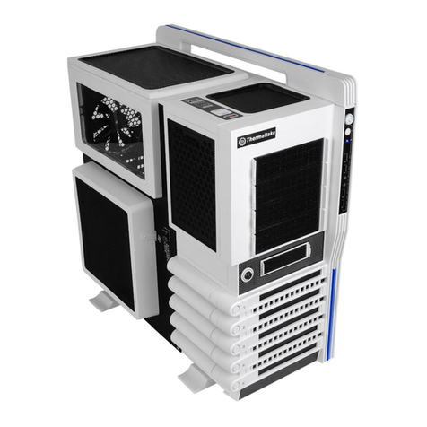
Other Thermaltake Enclosure manuals

Thermaltake H200 TG User manual

Thermaltake

Thermaltake H200 TG User manual

Thermaltake A2395 User manual

Thermaltake

Thermaltake A2395 User manual

Thermaltake Versa C22 RGB User manual

Thermaltake

Thermaltake Versa C22 RGB User manual

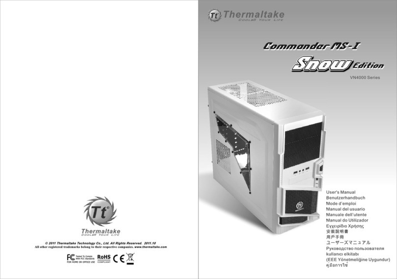
Thermaltake Commander MS-I SNOW Edition User manual

Thermaltake

Thermaltake Commander MS-I SNOW Edition User manual

Thermaltake CORE W100 series User manual

Thermaltake

Thermaltake CORE W100 series User manual

Thermaltake GTS VO3000 Series User manual

Thermaltake

Thermaltake GTS VO3000 Series User manual

Thermaltake Soprano Series User manual

Thermaltake

Thermaltake Soprano Series User manual

Thermaltake Element T VK9000 Series User manual

Thermaltake

Thermaltake Element T VK9000 Series User manual

Thermaltake Chaser A21 User manual

Thermaltake

Thermaltake Chaser A21 User manual

Thermaltake Level 10 GT User manual

Thermaltake

Thermaltake Level 10 GT User manual

Thermaltake Level 20VT User manual

Thermaltake

Thermaltake Level 20VT User manual

Thermaltake Level 20 User manual

Thermaltake

Thermaltake Level 20 User manual

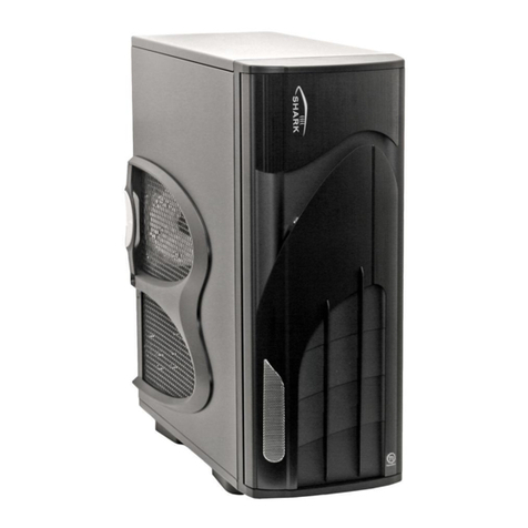
Thermaltake Shark User manual

Thermaltake

Thermaltake Shark User manual

Thermaltake H330 TG User manual

Thermaltake

Thermaltake H330 TG User manual

Thermaltake VN10006W2N User manual

Thermaltake

Thermaltake VN10006W2N User manual

Thermaltake ARMOR REVO GENE VO800M1W2N User manual

Thermaltake

Thermaltake ARMOR REVO GENE VO800M1W2N User manual

Thermaltake H100TG User manual

Thermaltake

Thermaltake H100TG User manual

Thermaltake Level 20 XT User manual

Thermaltake

Thermaltake Level 20 XT User manual

Thermaltake V200 TG User manual

Thermaltake

Thermaltake V200 TG User manual

Thermaltake V3 BlacX Edition VL800M Series User manual

Thermaltake

Thermaltake V3 BlacX Edition VL800M Series User manual

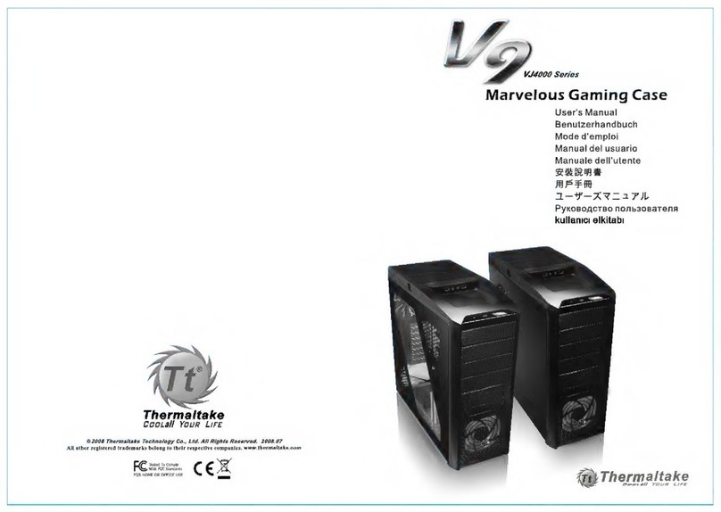
Thermaltake V9 VJ4000 Series User manual

Thermaltake

Thermaltake V9 VJ4000 Series User manual

Thermaltake View 71 TG User manual

Thermaltake

Thermaltake View 71 TG User manual

Thermaltake CA-1E3-00M1WN-03 User manual

Thermaltake

Thermaltake CA-1E3-00M1WN-03 User manual

Thermaltake Spedo Series User manual

Thermaltake

Thermaltake Spedo Series User manual

Popular Enclosure manuals by other brands

Conceptronic DDE03G quick guide

Conceptronic

Conceptronic DDE03G quick guide

multicomp pro MP004561 Assembly instructions

multicomp pro

multicomp pro MP004561 Assembly instructions

Stardom DR8-TB Hardware Installation User Manual

Stardom

Stardom DR8-TB Hardware Installation User Manual

VITECTOR FRABA JB 44 Series manual

VITECTOR FRABA

VITECTOR FRABA JB 44 Series manual

Seagate Exos CORVAULT Hardware installation and maintenance guide

Seagate

Seagate Exos CORVAULT Hardware installation and maintenance guide

3M 2178 instructions

3M

3M 2178 instructions

QUAD CONCOURSE CSUB - datasheet

QUAD

QUAD CONCOURSE CSUB - datasheet

Icy Box IB-WF200HD manual

Icy Box

Icy Box IB-WF200HD manual

StarTech.com UNI251BMU33 user manual

StarTech.com

StarTech.com UNI251BMU33 user manual

NAIM HDX-SSD - REFERENCE  ISSUE 1 Reference manual

NAIM

NAIM HDX-SSD - REFERENCE ISSUE 1 Reference manual

Macpower & Tytech Hydra S2 user manual

Macpower & Tytech

Macpower & Tytech Hydra S2 user manual

Heckler Design WindFall H604 Assembly & installation

Heckler Design

Heckler Design WindFall H604 Assembly & installation

ETERNAL RIVAL Art Fighstick manual

ETERNAL RIVAL

ETERNAL RIVAL Art Fighstick manual

Toa SB-30S Brochure & specs

Toa

Toa SB-30S Brochure & specs

Nanoxia Deep Silence 5 Rev. B manual

Nanoxia

Nanoxia Deep Silence 5 Rev. B manual

inXtron Taurus Super-S3 LCM Setup guide

inXtron

inXtron Taurus Super-S3 LCM Setup guide

RD S800 Assembly instructions

RD

RD S800 Assembly instructions

Bartec EJB Series Instructions for use

Bartec

Bartec EJB Series Instructions for use

manuals.online logo
manuals.online logoBrands
  • About & Mission
  • Contact us
  • Privacy Policy
  • Terms and Conditions

Copyright 2025 Manuals.Online. All Rights Reserved.