Thermo IEC Micromax 3590 User manual

SERVICE
MANUAL
SM3590
Revision 2
Micromax
Ventilated Microcentrifuge
Cat. No. 3590 -- For 120 VAC, 60 Hz
Cat. No. 3591 -- For 220 - 240 VAC, 50/60 Hz
Cat. No. 3595 -- For 100 VAC, 50/60 Hz
Refrigerated Microcentrifuge
Cat. No. 3592 -- For 120 VAC, 60 Hz
Cat. No. 3593 -- For 220 - 240 VAC, 50 Hz
Cat. No. 3594 -- For 220 - 230 VAC, 60 Hz
Cat. No. 3596 -- For 100 VAC, 50/60 Hz
300 Second Ave.
Needham Heights, MA 02429
Tel. (781) 448-8060
Fax (781) 444-6743
www.thermoiec.com

TABLE OF CONTENTS
1 INTRODUCTION..................................................................................................... 1
2 INSTALLATION ...................................................................................................... 2
2.1 Receiving the Unit ....................................................................................................2
2.2 Site Preparation........................................................................................................2
2.3 Power Configuration.................................................................................................3
2.4 Moving the Unit.........................................................................................................5
2.5 Front Panel ...............................................................................................................5
2.6 Refrigeration (RF only) .............................................................................................8
2.7 First Run ...................................................................................................................9
3 OPERATION ......................................................................................................... 10
3.1 Rotors and Accessories ...........................................................................................10
3.2 Operating Modes ......................................................................................................11
3.3 Warning Messages and Error Codes .......................................................................13
4 APPLICATIONS...................................................................................................... 15
4.1 Speed and Force Table............................................................................................16
4.2 Chemical Resistance Table......................................................................................17
4.3 Decontamination Table ............................................................................................18
5 MAINTENANCE...................................................................................................... 19
5.1 Cleaning ...................................................................................................................19
5.2 Cover Interlock Bypass ............................................................................................20
5.3 Troubleshooting........................................................................................................20
5.4 Table of Spare Parts.................................................................................................21
5.5 Fuses Not Replaceable By Operator .......................................................................21
5.6 Warranty ...................................................................................................................22
5.7 Condition of Returned Equipment ............................................................................22
6 SPECIFICATIONS .................................................................................................. 23
7 SERVICE ......................................................................................................... 25
7.1 Warnings ad Cautions ..............................................................................................25
7.2 Special Tools ............................................................................................................26
7.3 Troubleshooting........................................................................................................26
8 CABINET ......................................................................................................... 28
8.1 Cover Assembly .......................................................................................................28
8.2 Cabinet Housing .......................................................................................................29
8.3 Gaskets ....................................................................................................................30
8.4 Latch Assembly ........................................................................................................31
9 POWER CIRCUIT ................................................................................................... 33
9.1 General33
9.2 Troubleshooting........................................................................................................33
10 CIRCUIT BOARDS ................................................................................................. 35
10.1 General35
10.2 LEDs & Test Points ..................................................................................................36
10.3 Replacing the Circuit Boards....................................................................................37
11 DRIVE ASSEMBLY ................................................................................................ 39
11.1 Motor .....................................................................................................................39
11.2 Speed Sensor...........................................................................................................40
11.3 Brake .....................................................................................................................41
12 REFRIGERATION................................................................................................... 43
12.1 General43
12.2 Condensing Unit .......................................................................................................44
12.3 Refrigeration Relay...................................................................................................45
12.4 Thermistor ................................................................................................................45
12.5 Pressure Switch........................................................................................................46
13 DRAWINGS ......................................................................................................... 47

1 INTRODUCTION
The Micromax microcentrifuge is a quiet, high-speed bench-top
centrifuge for medical, industrial, and scientific laboratories. The
unit can achieve centrifugal force of up to 21,000 xg, making it
ideal for sedimentation of protein precipitates and separation of
blood serum.
NOTE: The Micromax microcentrifuge is available in two versions,
ventilated and refrigerated. The parts of this manual that apply to
the refrigerated version will be identified as RF only.
The unit reaches full speed within 15 seconds, even when fully
loaded, and brakes to a stop in approximately 15 seconds. It
features a maintenance-free, brushless motor and an easy-to-use
front panel which provides three versatile modes of operation:
automatic timed run, momentary spin (pulse) and continuous
operation (hold mode). Acceleration and deceleration rates may
be controlled to optimize runs - rapid for fast separations or slow
for delicate samples. Repeat runs with precisely the same speed
and time settings may be achieved at the touch of a button.
Micromax is a variable-speed unit with a range of 1000 to 15,000
RPM. The unit accommodates lightweight, dynamically-balanced
polypropylene rotors. The rotors cannot corrode, offer excellent
acceleration and deceleration characteristics and totally contain
tubes, allowing complete sample recovery even if a tube breaks.
The 891 rotor holds up to 24 sample tubes and provides aerosol
containment for biological samples. The 851 rotor holds up to 24
x 1.5-2 mL and 24 x 0.5 mL sample tubes, the 852 rotor holds up
to 48 x 0.5 mL or 24 x Microtainer tubes and the 853 rotor holds
up to 40 x 0.25 mL/0.4 mL or 6 x 50 mm glass tubes. Also, the
851 rotor has room to accommodate screw-cap microtubes,
microtube filters, and micro spin-columns. Section 4.1 provides a
speed and force table for these rotors.
A fail-safe cover interlock ensures that the cover is closed before
a run can begin and keeps the cover closed until the rotor has
reached a safe low speed (below 150 rpm), even in the event of a
power failure.
Micromax Series 1 Service Manual

2 INSTALLATION
2.1 Receiving the Unit
IEC ships the centrifuge in a carton that protects it from
shipping hazards. Retain the carton and packing material
through the warranty period in case you need to ship or
return the unit. Please be sure to complete the Warranty
Registration Card and return it to IEC.
2.2 Site Preparation
The unit normally resides on a bench-top. The Micromax
(ventilated model) can be placed in a cold room (no colder
than 0°C) for processing temperature-sensitive samples.
When you remove the centrifuge from a cold environment,
allow at least two hours for any condensate to evaporate
before using.
Note: When used in a cold room environment, some
bearing noise may become evident. The bearing lubricant
thickens at low temperatures. As the centrifuge speeds
up, it is thinned and distributed more evenly. Once this
occurs, any noise should subside.
The Specifications at the end of this manual give the
dimensions of the unit. Provide clearance of 8 cm (3
inches) at the rear and on both sides for heat dissipation.
Provide clearance of 28 cm (11 inches) above the unit to
open the cover.
Place the unit on a clean, dry surface to ensure that the
suction feet grip the surface firmly. Be sure that the area
beneath the unit is clear of debris and loose materials such
as paper. The surface must be level to ensure quiet,
vibration-free operation. A stable location is important
since an improperly-loaded unit can vibrate and the
centrifuge must not be permitted to move during operation.
Micromax Series 2 Service Manual

2.3 Power Configuration
The Micromax model numbers, and voltage and frequency
requirements are listed in the table below.
MODEL VOLTAGE FREQUENCY
3590 120 60 Hz
3591 220 - 240 50/60 Hz
3592 (RF) 120 60 Hz
3593 (RF) 220 - 240 50 Hz
3594 (RF) 220,230 60 Hz
3595 100 50/60
3596 (RF) 100 50/60 Hz*
Ensure that your site is configured to match the
centrifuge's power requirements. Plugging the Micromax
into incorrect voltage or frequency will void your
warranty.
* Line Frequency Selection
(3596, Micromax RF)
Locate the 50/60 Hz selector switch to the left of the power
receptacle at the rear of the centrifuge. Adjust this switch
to match the line frequency at the site.
Fuses Fuses are located at the back of the unit.
To install fuses:
Locate the power entry module on the back side of the
unit. The removable fuse drawer is located in the
module. A small latch holds the drawer in place. Press
this latch, then slide the drawer out.
• Cat. No. 3590: The fuse drawer will have one spare
and one active fuse installed at the factory. Fuse is
rated for 6.25 Amps (part no. 50606B).
• Cat. No. 3591: The fuse drawer will have two active
fuses installed at the factory. Fuse is rated for 4.0
Amps (part no. 43689).
• Cat. No. 3592: The fuse drawer will have one spare
and one active fuse installed at the factory. Fuse is
rated for 8 Amps (part no. 50606A).
Micromax Series 3 Service Manual

• Cat. No. 3593, 3594: The fuse drawer will have two
active fuses installed at the factory. Fuse is rated for
6.3 Amps (part no. 50607A).
• Cat No. 3595: The fuse drawer will have one spare and
one active fuse installed at the factory. Fuse is rated for
8.0 Amps (part no. 50021).
• Cat No. 3596: The fuse drawer will have one spare and
one active fuse installed at the factory. Fuse is rated for
10.0 Amps (part no. 49998). Note that the frequency
selector adjacent to the power entry module must be
set for the correct frequency.
Ensure that the fuses are securely in place and reinstall
the entire drawer into the power entry module.
Power Cord IEC provides a power cord with each Micromax centrifuge.
The unit requires a grounded power supply (3-prong power
outlet). If your facility does not have properly grounded
power outlets, arrange for proper grounding. Do not
remove the grounding pin from the centrifuge power cord.
Do not use an adapter to connect to a 2-prong outlet.
Micromax Series 4 Service Manual
2.4 Moving the Unit
Suction cups located on the base of the unit are a safety
feature which adhere it to the work surface to prevent it
from moving. To move the unit to another location, insert
an object such as a tongue depressor under each suction
cup to break the vacuum seal of that cup (taking care not
to damage the suction cup surface). When all four cups
are disabled, you can easily lift the unit. When the unit is
in its new location, ensure that the suction cups fully
contact the benchtop again.
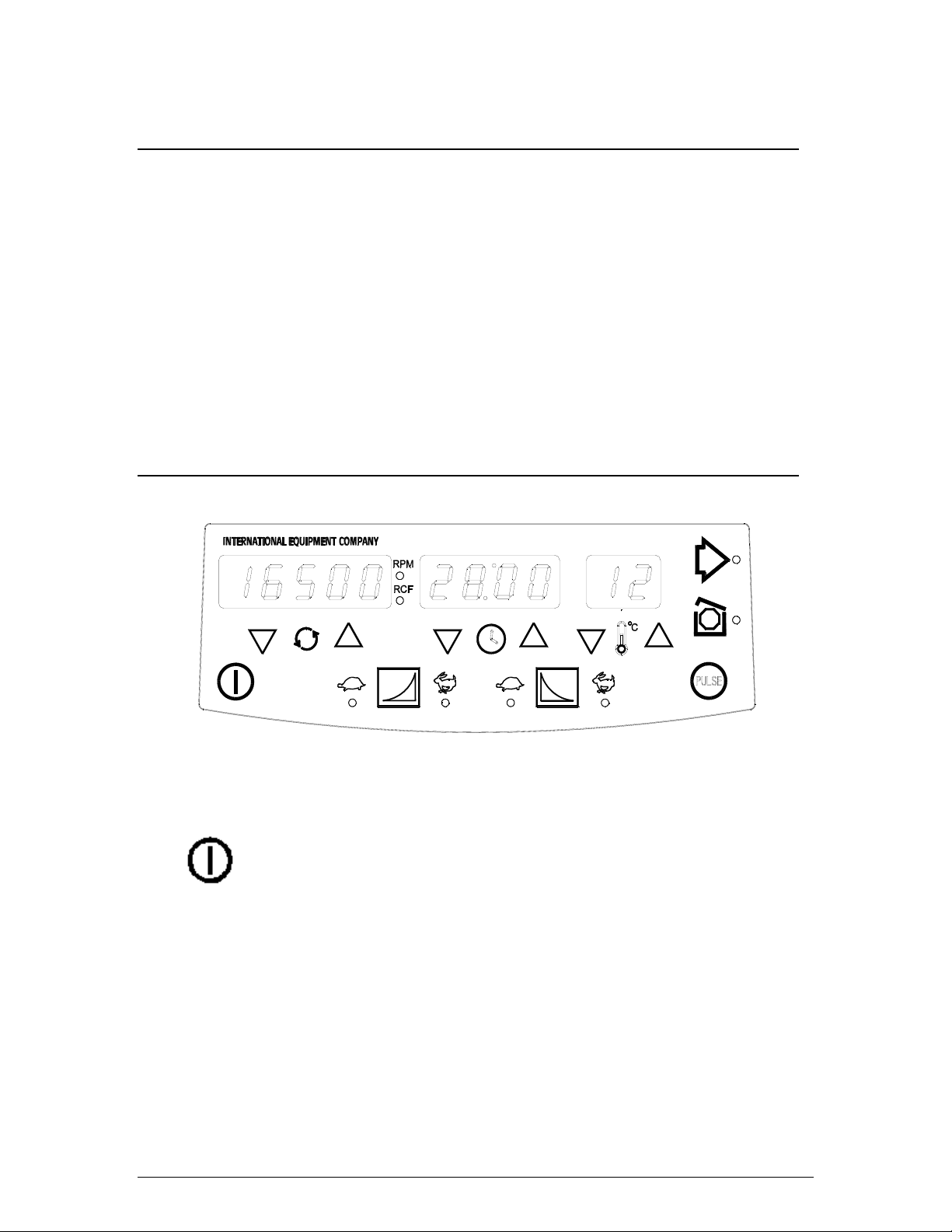
2.5 Front Panel
Figure 1: The Front Control Panel
The On/Off button must be on to use the unit. This button
applies power to the control panel and refrigeration system
(RF only). The red STOP light indicates that the centrifuge
is plugged in. (In RF models, temperature is displayed
whenever the unit is plugged in.) The On/Off button is
inoperative during the actual run. Shut off refrigeration with
the On/Off button, but stop a run with the STOP button.
The control panel contains numeric displays for RPM/RCF
(SPEED/FORCE), TIME and TEMPERATURE (RF only).
These displays have two states or modes: Actual and Set.
In the Actual mode, they indicate current run conditions
such as:
Micromax Series 5 Service Manual

• rotor speed or force
• elapsed time of, or time remaining in, the run
• actual temperature (RF only).
The display in the Set mode indicates the desired settings
for the run and is operative:
• whenever you use the up and down arrows
• briefly at the start of a run
• briefly after the unit is switched ON
When the display shows Actual parameters, the numbers
are bright; when the display shows Set parameters, the
numbers are dim. The numeric displays can also display
warning or error messages (see Section 3.3). Descriptions
of the displays appear below.
The displays for the Micromax are:
Speed/Force display: The number in the display above
this symbol represents the rotor speed in RPM or force in
RCF. When RPM is selected the display indicates
revolutions per minute. When RCF is selected the display
indicates relative centrifugal force. Press this button to
toggle between RPM and RCF. Use the arrow buttons to
change the set speed or force. The display shows speed
within 100 RPM and never requires calibration. Select
speed in increments of 100 RPM from 1000 through
15,000 RPM. Select RCF in increments from 1 - 1000 xg
by 50 xg, from 1,000 - 10,000 xg by 100 xg, and from
10,000 - 21,000 by 200 xg.
Time display: The number in the display above this
symbol indicates time. Time is displayed as
minutes:seconds. You can set time from 1 second to 99
minutes using the arrow buttons. In normal timed mode,
the system counts down from set point. In continuous or
momentary spin modes, the system counts up.
Temperature display: The number above this symbol
represents temperature in whole degrees Celsius from -
9 °C through 40 °C (RF only).
Micromax Series 6 Service Manual

Use the arrow buttons to view or change the Set
parameters for Speed/Force, Time or Temperature (RF
only). The first time the button is pressed, the numeric
display simply switches from Actual readings to Set
parameters, without changing them. If you press the
button again, the selected parameter increases or
decreases once for each press. If you hold the button
down, the setting changes repeatedly until you release the
button.
The longer you hold the button down, the more rapidly the
setting changes. Usually, you hold a button down to
approach a desired setting, then press the up or down
button repeatedly to select the exact setting. When you
release the arrow buttons for 3 seconds, the display
returns to the Actual readings.
Acceleration/Deceleration: The user has the option of
setting either full (rapid) or gentle acceleration and braking.
The gentle option may be used to avoid mixing of density
gradients or breakup of pellets. A description of the two
options follows:
This button is used to increase rotor acceleration (up to
1500 RPM) or rotor deceleration. If the yellow light over
the rabbit is lit, then full acceleration/deceleration is
selected.
This button is used to decrease rotor acceleration or
deceleration. If the yellow light over the turtle is lit, then
slow acceleration/deceleration is selected. Slow
acceleration takes from 5 to 10 seconds to achieve 1500
RPM, depending on the rotor and its contents. In slow
braking, the rotor will coast down from 1500 RPM. If no
light is lit, the rotor coasts naturally to a stop.
When using the 851, 852 , 853 or 891 rotors the difference
in time between full and slow braking is approximately a
half second.
This button starts a run. The run is governed by the Set
parameters. The associated green light blinks until the
rotor reaches the set run speed. Then the light stays on
until the end of the run. On some ventilated units only, the
cover opens at the end of a run.
Micromax Series 7 Service Manual

This button stops the run, and unlocks the cover when the
rotor has slowed to below 150 rpm. (A run will also stop
automatically when the set time has elapsed or the
momentary run button is released.) The red light will flash
as an indication that the rotor is still slowing down
(braking). When the run ends, the red light stays on,
indicating that the rotor has stopped and the cover can be
opened.
The centrifuge will run up to set speed while this button is
pressed, and stop when it is released.
2.6 Refrigeration (RF only)
Models 3592, 3593, 3594 and 3596 are refrigerated
models. Whenever the cover of one of these units is
closed and the unit is switched ON, the refrigeration
system begins to cool the rotor chamber to the set
temperature.
Note: The unit is not designed for use as a refrigerator.
The natural fanning action of rotor serves to maintain a
uniform temperature distribution inside the chamber.
Therefore, at zero RPM, there is no correlation between
set and actual chamber temperatures.
If a run begins and the rotor chamber is not at the specified
temperature, the run will not be aborted. If desired, press
STOP to discontinue the run and pre-cool the chamber by
spinning the rotor (empty) until you are satisfied with the
temperature.
If a temperature higher than ambient is specified, the units
will not heat the rotor chamber except through the normal
heating effect of the equipment (friction and motor heat).
Remove frost or condensation from the rotor chamber by
first allowing it to melt and then removing it with a sponge
or cloth. When a centrifuge is not in use, turn it off or leave
the cover open (disables refrigeration).
Micromax Series 8 Service Manual

2.7 First Run
Plug in the centrifuge. If an arrow key is pressed first, the
display will briefly show 10,000 RPM, 1:00 minute and 25
°C (RF only) the default set values. Press the Stop/Open
Cover button to release the cover interlock. Open the
cover. Remove any loose material from the rotor chamber.
Install a rotor, as described in Section 3.1. Close the cover
and press it down until it latches.
Use the up or down arrow buttons to select Set
parameters. Experiment with the buttons to see how they
control the displayed settings. Press and hold a button to
scroll quickly. This does not activate the rotor. Note that,
when you release all buttons for over 3 seconds, the
display returns to Actual readings.
Select an appropriate time, speed and temperature (RF
only) and then press the START button. The rotor will
accelerate to set speed, spin for the set time, and brake to
a stop. Press the Stop/Open Cover button to release the
safety interlock.
Micromax Series 9 Service Manual

3 OPERATION
3.1 Rotor and Accessories
A balanced load is essential with all high-speed
centrifuges. An unbalanced load produces vibration and
causes excessive wear of motor bearings. Therefore,
always load the rotor symmetrically. When using tube
adapters, install an adapter in the opposite tube position.
The total weight of samples loaded in opposing positions
must be equal in weight to within 1.0 gram. The position
numbers, present on rotors, identify opposing tube
positions.
Samples of different specific gravities can be processed in
the same run, provided that the samples of a given type
are balanced around the rotor as though they were the
only ones in the rotor.
Rotor Installation To install the rotor, lower it straight onto the shaft. Align the
holes in the rotor with the positioning pins on the shaft. To
do this, hold the rotor in one hand and hold the shaft, as it
protrudes through the rotor, with the other hand. Rotate
them in opposite directions until the pins line up with the
holes and the rotor drops down into position. Do not apply
excessive force. Screw the metal locking nut (clockwise)
on the shaft to hold the rotor down. Be sure the orange
rubber ring is facing downward. Hold the rotor and tighten
the nut moderately with your fingers; do not over tighten it.
The 891 rotor cover must be installed prior to the rotor
being placed in the centrifuge. Verify that the o-ring seals
(2) are in place around the outer and inner perimeters of
the rotor. To install the cover, place the rotor on a flat
surface and then place the rotor cover on top of the rotor.
Using the palm of your hand(s), press down evenly around
the cover to fully engage the seals.
The 851, 852 and 853 rotor covers prevent generation of
aerodynamic noise during the spin. It also prevents gross
aerosol effects in the event of tube failure. It fits snugly
over the rotor and pulls off easily. To place it properly,
rotate the cover until it drops easily onto the adapter
spline. Press down until the rim of the cover contacts the
rotor. The spline at the top of the shaft adapter drives the
lid during rotation.
Micromax Series 10 Service Manual

Caution: Improper placement of the cover may allow it
to come off during a spin.
Rotor Removal To remove the rotor, first remove the cover (851, 852 or
853 only). Then unscrew (counterclockwise) and remove
the metal locking nut. The rotor can now be lifted straight
out of the rotor chamber. You can refrigerate the rotor
without removing the tubes but do not operate the rotor
when the rotor temperature is below 0°C.
To remove the 891 rotor cover, place the rotor on a flat
surface. Place your thumbs on the inner perimeter of the
cover, and your fingers on the outer edge. Pry it up from
the outer edges.
3.2 Operating Modes
The Micromax Models offer three operating modes: Timed,
Continuous (Hold), and Momentary.
Timed Run To start a timed run or spin:
Select the Set parameters using the control panel buttons
(refer to Section 2.5) and then press START.
• To view the set parameters at any time, press any
arrow key.
• The spin duration may be changed at any time, even
during the spin, by pressing the arrow keys until the
new desired setting(s) is displayed. If a time less than
the elapsed time is programmed (for example, one
second), the spin ends immediately. If a time greater
than the elapsed time is programmed, the elapsed time
continues until the newly selected time is reached (the
time does not reset).
The speed and temperature (RF only) may similarly be
changed during a run. Three seconds after the
parameter's arrow key is released, the centrifuge will
adjust to the newly set parameter.
Micromax Series 11 Service Manual

Hold Mode To set Hold (continuous) mode:
Select the Set parameters using the control panel buttons
(refer to Section 2.5). Scroll down through zero time on
the Time display until the word Hold appears in the display.
This mode is used for runs greater than 99 minutes.
Momentary To operate in the momentary mode:
Select the Set parameters using the control panel buttons
(refer to Section 2.5). Press and hold the PULSE button.
The run begins when you press the button and ends when
you release the button.
NOTE: In this mode the unit displays Set parameters for
three seconds, the time display counts upward and
displays the elapsed time since you pressed the PULSE
button.
In this mode very quick separations can be performed, or
you may closely monitor the progress of a run. (This is
useful for easily separated samples, for simultaneous
mixing of samples, and to deposit condensate droplets at
the bottom of the tube.)
Micromax Series 12 Service Manual

3.3 Warning Messages and Error Codes
The beeper sounds in three situations:
• Two times on power up.
• Three times at the end of a spin.
• When a warning occurs (three times).
Warnings appear in place of the numeric displays in the
following cases:
HEAD This appears if a run is started without
loading a rotor into the chamber. Opening the cover resets
this warning. This warning is disabled when slow
acceleration is selected.
Lld This appears briefly if you press the START
button but the cover is not closed. Closing the cover resets
the warning.
PFAIL This appears at the end of a power failure
that interrupts a run if the rotor is still spinning when power
is restored. Press STOP to reset this warning.
Error Codes require factory-authorized maintenance. A
typical error means the internal microprocessor has
detected impermissible readings or a failure elsewhere in
the unit. An error code number appears on the front panel.
When an error code is displayed first unplug and reconnect
the unit to power and try the run again. If the error code
reappears, tell the service personnel which number
appeared when you report the problem.
Micromax Series 13 Service Manual

Err 1 No Tachometer
Tachometer signals were not present during run. The rotor
coasts to a stop. Cover opening is inhibited after this error.
OSPd Overspeed
Speed is 15,200 RPM. The rotor will brake to a stop
run A Runaway
During stopping, rotor has not been decelerating for 8
seconds, or when at standby, rotor speed exceeds 600
RPM. The rotor coasts to a stop.
rEFr Refrigeration Failure (RF only)
The unit displays this code if the measured temperature
exceeds 45 °C at any time during the run.
FSAFE Fail-safe Time-out
Independent circuitry on the circuit board has sensed a
lack of activity from the control microprocessor. All power
outputs are disabled (including motor, latch solenoid, etc.).
COPF COP Watchdog/OpCode Trap Error
The microprocessor itself has sensed a lack of activity
from the program that controls the centrifuge. The rotor
coasts to a stop.
COP COP Watchdog Not Enabled
The microprocessor COP is not enabled. The rotor coasts
to a stop.
UndFI Undefined Interrupt
The microprocessor was interrupted by an undefined
source. The rotor coasts to a stop.
ILLOP Op-Code Trap Error
The rotor coasts to a stop.
Warnings during a spin. The "HEAd", "Lld", "PFAIL" and
"Error” messages can occur during a spin. In this case, the
rotor brakes or coasts to a stop and the run ends.
Micromax Series 14 Service Manual

4 APPLICATIONS
Misapplication of any tube can cause tube rupture. To
avoid this, never spin tubes faster than their recommended
G-force, and never centrifuge disposable tubes more than
once. If the tubes are not rated for the needed force, use
more suitable tubes. If breakage does occur, residue will
be captive in the tube cavity in the rotor. You may be able
to recover it by pipetting.
Corrosive solvents Your IEC centrifuge is made of materials designed to resist
attack from common laboratory chemicals. The rotor and
lid are made of polypropylene and the interior of the rotor
chamber is stainless steel. Use covered sample tubes if
the samples contain acids or solvents known to attack
these materials. Promptly cleaning spills from the rotor
and from the sample chamber minimizes the effects of
corrosive chemicals. Replace any component that exhibits
crazing, frosting, peeling, or similar faults. Do so before
any resulting vibration requires more expensive repair.
Replace the shaft adapter, rotor, lid, or metal locking nut if
they become cracked, scratched, or gouged.
Sample Heating The rotor chambers of Models 3590 and 3591 centrifuges
are ventilated during operation. However, during very long
runs, some heat inevitably travels to the samples. You can
minimize sample heating by placing the unit in a refrigerator
or cold room.
Micromax Series 15 Service Manual

4.1 Speed and Force Table
Rotor Cat. No. No. of Tubes and Tube Size Adapter
Cat. No
Max Speed
(RPM)
Max RCF
(xg)
Radius (cm)
24 x 1.5ml - 21004 8.35
891124 x 0.6ml B/D Microtainers™ 5763** 21256 8.45
(Aerosol 24 x 0.5ml PCR microtubes 5763** 15000 18740 7.45
Contained) 24 x 0.4ml microtubes 5764** 21004 8.35
24 x 0.25ml microtubes 5764** 18237 7.25
24 x 1.5ml - 21004 8.35
24 x 0.6ml B/D Microtainers™ 5763** 21256 8.45
24 x 0.5 ml microtubes - 17432 6.93
851224 x 0.5ml PCR microtubes 5763** 15000 18740 7.45
24 x 0.4ml microtubes 5764** 21004 8.35
24 x 0.25ml microtubes 5764** 18237 7.25
48 x 0.5ml PCR microtubes - 20124 8.00†
852215000 18866 7.50‡
24 x B/D Microtainers™ - 21633 8.60†
40 x 0.4ml microtubes - 21130 8.40
853240 x 0.25ml microtubes - 15000 18866 7.50
40 x 0.8ml (6x50mm) glass - 21382 8.50
Microtainers™ is a trademark of Becton Dickinson
* RCF displayed on control panel is based upon radius of rotation for 891 and 851 rotors for 1.5/2.0ml
tubes (8.35cm).
** Order 2 pks of adapters separately. IEC 5763 and 5764 are packaged 12/pk.
† Outer row holds 24 tubes
‡ Inner row holds 24 tubes
1IEC 891 Rotor
Provides Aerosol Containment and has been tested for microbiological containment by PHLS-
CAMR, Porton Down. Meets requirements of US OSHA Bloodborne Pathogen Final Rule:
(Regulation 29 CFR Part 1910.1030. Complete with IEC 50417 Aerosol Containment Cover, IEC
50525 Inner and IEC 36597 Outer rubber O-ring seals.
2IEC 851, 852, 853 rotors
Micromax Series 16 Service Manual

4.2 Chemical Resistance Table
Plastic Metal Other
PA PC PE PP PU NL DN CN NN PS TI SS AL MB MG RR BN VN PF
Acids,diluteorweak EEEEGEFNFEGGFFNFEEE
Acids*, strong or conc. E N E E F N N N N F N N N N N N F G N
Alcohols, aliphatic E G E E F E E E N E E E E E F E E G E
Aldehydes G F G G G G G G F N E E E E E E N E E
Bases ENEENGNGFEEEEEEGGNN
Esters GNGGNEGGE NE E EE ENNNE
Hydrocarbons, aliphatic G F G G E N E E E N E E E E E N E E E
Hydrocarbons, aromatic F N G F N N E E E N E E E E E N N E E
Hydrocarbons, halogenated F N F F N N G E G N E E E E N N N F E
Ketones GNGGNNEEENEGGGENNNE
OxidizingAgents,strong FNF FNNNNNNEFNNNNFEE
Salts EEEEEEEEEEEFFFNEEEE
*For Oxidizing Acids, see "Oxidizing Agents, strong".
PA - POLYALLOMER TI - TITANIUM
PC - POLYCARBONATE SS - STAINLESS STEEL
PE - POLYETHYLENE AL - ALUMINUM
PP - POLYPROPYLENE MB - MANGANESE BRONZE
PU - POLYURETHANE MG - MAGNESIUM
NL - MODIFIED PHENYLENE OXIDE (NORYL) RR - RUBBER
DN - ACETAL HOMOPOLYMER (DELRIN) BN - BUNA-N
CN - ACETAL COPOLYMER (CELCON) VN - VITON
NN - NYLON PF - PHENOLIC FIBER
PS - POLYSTYRENE
Classification of Resistance
E= Excellent
G= Good
F= Fair
N= Not Recommended
Micromax Series 17 Service Manual

4.3 Decontamination Table
Compatible Processes For Decontamination
Sterilization Methods Plastic Metal Other
PA PC PE PP PU NL CNDN NN PS TI SS AL MGMB RR BN VN PF PT
Mechanical
Chemical
Autoclave*
Ethylene Oxide Gas
Dry Heat 160°C@2Hrs.
Ethanol
40% Formalin
Methanol
2-Propanol
5% Sodium Hypochlorite**
3% Hydrogen Peroxide
100% Hydrogen Peroxide
5% Phenol Solution
SMUSMUSSSU
SSSSSSSSSS
UUUUUUUUUU
SSSSS
SSSSS
SS
S
SSU
SSMSM
UUSSS
UUUUU
SSSSSSSSSSSSSSUSSSUM
SSSSUSSSSUSSSSSSUSSS
SMSSMSSSUMSSSSSSSUSS
SSSSMSSSUSSSSSMSSSSS
SSSSUSUUUSSMUUUSUSSM
SSSSSSMSUSSSSSUSSSSM
SSSSSUUUUSSSSSSUUSSU
MUU UUMMU MMMMMMMUS S U
PA - POLYALLOMER
PC - POLYCARBONATE
PE - POLYETHYLENE
PP - POLYPROPYLENE
PU - POLYURETHANE
NL - MODIFIED PHENYLENE OXIDE (NORYL)
DN - ACETAL HOMOPOLYMER (DELRIN)
CN - ACETAL COPOLYMER (CELCON)
NN - NYLON
PS - POLYSTYRENE
TI - TITANIUM
SS - STAINLESS STEEL
AL - ALUMINUM
MB - MANGANESE BRONZE
MG - MAGNESIUM
RR - RUBBER
BN - BUNA-N
VN - VITON
PT - PAINTED SURFACES
PF - PHENOLIC FIBER
*Autoclaving
121°C 20 min.@
2 ATM (15 PSIG)
**Household Bleach
S=SATISFACTORY
M=MARGINAL
U=UNSATISFACTORY
WARNING:
This chart describes the material compatibility of various sterilization methods. It does not specify the
adequacy of sterilization. Refer to section 4.3 Chemical Resistance Table for material compatibility
during centrifugation.
Micromax Series 18 Service Manual
This manual suits for next models
6
Table of contents
Other Thermo IEC Laboratory Equipment manuals


Popular Laboratory Equipment manuals by other brands


V&P Scientific
V&P Scientific SpinVessel VP 418SV3-1-850RB-CC operating instructions

Tecno-gaz
Tecno-gaz Multisteril Fast Technical manual

Waters
Waters Xevo TQD Overview and maintenance guide

Intellinet
Intellinet 561518 instructions

Waters
Waters Xevo TQD IVD Overview and maintenance guide

CAPP
CAPP PA-100 Operation manual