Streck ESR-Auto Plus 506 User manual
ESR-Auto Plus®Operator’s Manual
Model 506, v 1.0-2.0


ESR-Auto Plus Operator’s Manual I
Thank you for choosing the ESR-Auto Plus®, the most
accurate, reliable and user-friendly automated ESR
analyzer available today! Our dedicated employees
are here to make your ESR-Auto Plus experience as
simple as possible.
This manual covers the operation and conguration
of the ESR-Auto Plus Model 506, the ESR-657 Mixer
and the ESR Barcode Scanner.
The following item is included with this manual for your
convenience:
QUICK REFERENCE GUIDE
A simple, condensed guide to the most common
instrument functions.
TECHNICAL SERVICE DEPARTMENT
800.843.0912 (ext. 7510)
technicalservic[email protected]
The ESR-Auto Plus is supported by a staff of
experienced Medical Laboratory Scientists who
welcome the opportunity to assist you. Our on-
site Technical Service Representatives have
immediate access to the ESR-Auto Plus, and they
are an excellent resource to answer your product
questions.
Contact Streck for:
• Assistance with implementation of the ESR-Auto Plus
• Technical support for the entire ESR product line
• Processing ESR-Auto Plus correlation data
We want your relationship with our company to
extend beyond being satised with our product. It
is our privilege to serve you, and we are looking
forward to your next call.
STANDARD WARRANTY
Streck warrants the ESR-Auto Plus, ESR-657 Mixer
and ESR Barcode Scanner to be free from defects in
workmanship and materials during normal use for a
period of one year from the date of purchase. If any
defects occur during the warranty period, contact
Streck Technical Service Department. This warranty
does not cover defects or malfunctions which occur
due to instrument abuse, improper maintenance or
unauthorized repairs.
INSTRUMENT RETURN POLICY
Any claim for credit or return of instruments for any
reason must be made within 30 days of receipt of
the instrument. Returns executed within 30 days of
receipt will result in an automatic reassignment of the
instrument title back to Streck. The customer will be
responsible for return freight charges on all customer-
initiated instrument returns. All instruments approved
for return will be subject to a $100 return fee.
• The customer must repackage the instrument(s) in
its original packaging to ensure that the components
do not shift during shipment. Refer to Section 9.7 for
repackaging instructions.
• The customer must contact their Streck Sales
Representative to obtain a return authorization
number, which must be clearly marked on the
outside of the package.
Manufactured For:
Streck
7002 S. 109 Street
La Vista, NE USA 68128
800-843-0912
402-333-1982
Welcome to Streck!

320597-3 - NOVEMBER 2016
II ESR-Auto Plus Operator’s Manual
Table of Contents
1Introduction
1.1 ESR Components 1
1.2 Unpacking Instructions 2
1.3 Barcode Scanner Installation 2
1.4 Cable Connections 2
1.5 Barcode Scanner Calibration 2
1.6 Installing Printer Paper 3
1.7 Removing Paper 3
1.8 Instrument Set-up 3
2Sample Preparation & Analysis 5
2.1 ESR-Vacuum Tubes 7
2.2 Sample Collection 7
2.3 Phlebotomy Guideline 8
2.4 Mixing a Sample 8
2.5 Secondary Patient Labels 9
2.6 ESR Tube Labeling Sleeves 10
2.7 Starting a Sample 11
2.8 Reporting Results 11
2.9 Canceling a Sample 11
3 Keypad & Menu Overview 13
3.1 Keypad Overview 15
3.2 Menu Diagram 15
4Menu Functions 1-5 17
4.1 Standby Menu 19
4.2 Menu 1: Search Sample 19
4.3 Menu 2: Check Position 20
4.4 Sample Status 20
4.5 Menu 3: Print Log File 21
4.6 Menu 4: Control Samples 22
Run, Show, Register and Edit Controls
4.7 Menu 5: Run Test Rack 27
5Menu Function 6 - User Cong. Menu 29
5.1 Accessing Menu 31
5.2 Print Set Up 31
5.3 Set Date and Time 32
5.4 Set Audible Alarm 32
5.5 Set Printer Function 33
5.6 Set Print Style 33
5.7 Set Access Code 34

ESR-Auto Plus Operator’s Manual III
6 Menu Function 6 - Service Menu 35
6.1 Accessing Menu 37
6.2 Set Language 37
6.3 Set Date and Time Style Formats 38
6.4 Registering Test Rack 39
6.5 Set Tube Type 40
6.6 Set Calibration 40
6.7 Set Test Mode 41
6.8 Set Access Code 41
6.9 See Temperature 41
6.10 RAM Reset 42
7Background of the ESR Test 43
7.1 The History 45
7.2 The Original 200mm System 45
7.3 The 100mm Vacuum System 45
7.4 BD Standard Scale vs. QuickMode Method 45
7.5 The ESR-Vacuum Tube 46
7.6 A Typical ESR Reaction 47
7.7 ESR Reference Ranges / Values 47
8Performance & Technical Specications 49
8.1 Overview 51
8.2 Measuring Abnormal Samples 51
8.3 Fill Level 51
8.4 Temperature Compensation 52
8.5 ESR-Auto Plus Precision 52
8.6 Preventive Maintenance 52
8.7 Cleaning Instructions 52
8.8 Barcode Scanner 53
8.9 Data Output 53
8.10 Technical Specications, ESR-Auto Plus 54
8.11 Environmental Conditions 55
8.12 Transportation Environment 55
8.13 Technical Specications, ESR-657 Mixer 56
8.14 Disclaimer 56
9Safety Precautions 57
9.1 User Precautions 59
9.2 Electrical Equipment 59
9.3 Disconnect Device 59
9.4 Sample Analysis 59
9.5 Application of Secondary Labels 59
9.6 Removal of ESR-Vacuum Tubes 60
9.7 Repackaging Instructions 60
9.8 Glossary of Safety Symbols 60
10 Troubleshooting 61
10.1 Error Codes 63
10.2 Status Codes 64
10.3 Troubleshooting Guide 65
11 Quick Reference Guide 67
11.1 Standby Screen 69
11.2 Sample Mixing 69
11.3 Run Test Rack 69
11.4 Register New Lot of QC 69
11.5 Run QC Sample 70
11.6 Run Patient Sample 70
11.7 Cancel Measurement 70
11.8 Predict Sample Result 70
11.9 Re-Register Test Rack 71
QC Maintenance Record 73


1
Introduction


ESR-Auto Plus Operator’s Manual 1
The ESR-Auto Plus®is designed to accurately and precisely
measure the sedimentation rate of erythrocytes (red
blood cells) in Streck ESR-Vacuum Tubes. The results are
recorded as millimeters (mm) per hour (Westergren Method)
by converting to the QuickMode method, a scientically
developed method for measuring ESR in only 30 minutes.
The instrument compensates for temperatures above 26° C
(79° F).
Results are automatically reported to an internal printer.
The instrument may also be interfaced with a Laboratory
Information System (LIS) or a computer. To reduce errors
with patient identication and labeling, the instrument can be
equipped with a barcode scanner.
The mixing process prior to evaluation of an ESR sample is
critical. For this reason, the ESR-657 Mixer is available as
an additional accessory. The ESR-657 Mixer operates using
a slow 360° rotation, which ensures complete mixing and
more accurate results.
The ESR-Auto Plus and ESR-657 Mixer are IVD Medical
Instruments.
1.1 ESR Components
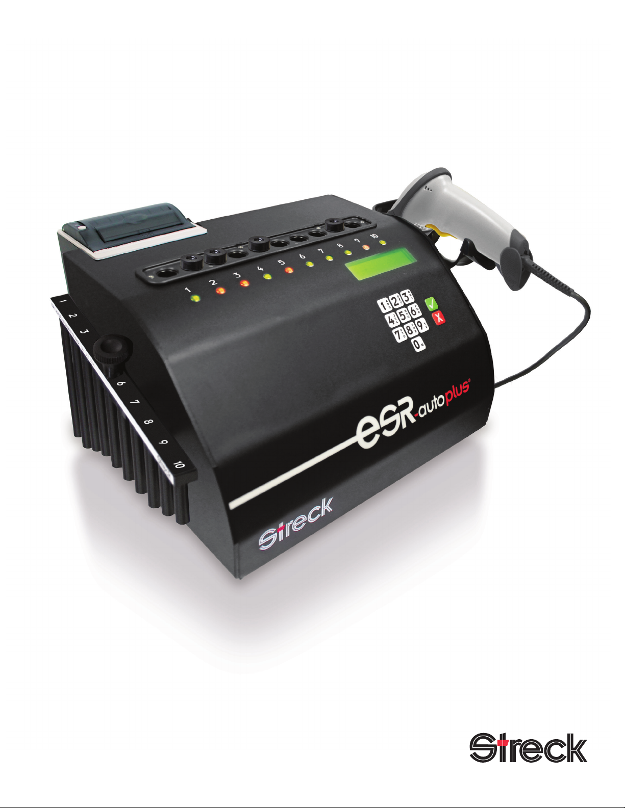
ESR-Auto Plus (Figure 1a)
The ESR-Auto Plus analyzer can process up to 20 samples
per hour. Samples are read by infrared light using a
measuring arm, which is controlled by a motor.
ESR-657 Mixer (Figure 1b)
The ESR-657 Mixer is designed to mix Streck ESR-Vacuum
Tubes prior to evaluation. Its unique motion ensures proper
mixing of samples. The ESR-657 Mixer can hold up to 10
ESR-Vacuum Tubes.
ESR-Vacuum Tubes (Figure 1c)
ESR-Vacuum Tubes are available in 1.2ml and 2.0ml vacuum
draw sizes and are designed specically for use with the
ESR-Auto Plus, ESR-657 Mixer and ESR-10 Manual Rack.
High Altitude and Safety Coated 1.2ml tube congurations
are also available.
ESR Barcode Scanner (Figure 1d)
Symbol barcode scanner (catalog #240329, mfr. part #
LS2208-SR20001) connects to the ESR-Auto Plus using a
USB cable, (mfr. part #CBA-U21-S07ZAR). It is compatible
with most available barcodes: EAN, UPC, Codabar, Code
39, Code 93, Code 128, Interleaved 2 of 5, and several more.
The barcode scanners are considered to be Class 2 lasers
that emit Class 2 laser light.
Chapter 1 |Introduction
Figure 1a:
ESR-Auto Plus
Figure 1b:
ESR-657 Mixer
Figure 1c:
ESR-Vacuum Tubes
Figure 1d:
ESR Barcode Scanner

320597-3 - NOVEMBER 2016
2 ESR-Auto Plus Operator’s Manual
1.2 Unpacking Instructions
Retain all packaging materials for shipping, moving or
storing the instrument.
1. Open the box and remove the top foam piece, which
contains accessories such as the ESR-657 Mixer,
barcode scanner, power cords and paper.
2. Carefully lift the instrument out of the bottom foam piece
and remove the anti-static shipping bag.
3. Install the ESR-Auto Plus and ESR-657 Mixer on a level,
supported surface that is free from any vibrations or
temperature uctuations.
Important! Vibrations and temperature
uctuations may adversely affect ESR results.
Refer to Section 8.4 for more information on the
impact of temperatures on ESR results.
1.3 Barcode Scanner Installation
1. Line up holes in barcode scanner bracket with pre-drilled
holes on the right side of the ESR-Auto Plus (Figure 2a).
2. Tighten the screws using the 3mm allen wrench
(provided). Do not over-tighten screws (Figure 2a).
3. Connect the barcode scanner to the socket marked
“Barcode Input” on the back of the instrument (Figure 2b).
4. Place the barcode scanner in the barcode scanner
bracket as shown (Figure 2c).
1.4 Cable Connections (Figure 3)
1. Connect the external printer cable or mainframe computer
cable (LIS) to the USB port marked “Data Output”
(optional).
2. Connect the AC power cord to the power inlet on the
back of the ESR-Auto Plus.
3. Connect the 24V AC power cable to the ESR-657 Mixer.
The mixer will rotate continuously when the power switch
is on.
Important! Plug the instrument and mixer power
cords into a power surge protector to guard
against power surges and uctuations.
1.5 Barcode Scanner Calibration
1. Scan a patient barcode three times to calibrate the
barcode scanner.
2. If the barcode scanner is unplugged, scan a barcode three
times to re-calibrate before scanning a patient sample.
Important! The barcode scanner has been pre-
programmed and is ready to use. If you encounter
any problems with the operation of the barcode
scanner, contact Technical Service.
Figure 2a
Figure 2b
Figure 2c
Figure 3
AC
Power

ESR-Auto Plus Operator’s Manual 3
CAUTION: Use care to avoid cutting nger on
paper cutter.
1.6 Installing Printer Paper (Figure 4)
1. Before installing the paper, remove any residual glue or
tape sealing the new roll.
2. Pull up the lever on the printer lid to release the paper
cover lock (Figure 4a).
3. Place a roll of paper in the printer with the paper extending
out of the printer toward the front of the ESR-Auto Plus
(Figure 4b).
4. Press rmly on the paper cover to close the printer lid
(Figure 4c).
5. Press the paper feed button on the printer to advance
the paper and verify the paper roll is installed correctly. If
the paper does not feed properly, open the printer lid and
realign the paper.
Important! Streck thermal paper is specically
approved for use with the ESR-Auto Plus printer
and should be used to prevent damage to the
print head. Alternate paper may have different
technical specications that cause premature
wear and tear.
1.7 Removing Paper
1. Open the printer lid.
2. Remove the paper and close the printer lid.
1.8 Instrument Set-up
This section outlines the menus to review before getting
started. A thorough review of the Operator’s Manual is
strongly advised prior to reporting patient results. Refer
to Chapter 3 for a menu diagram and an overview of the
keypad.
1. Date & Time: Set the date and time in the User
Conguration Menu (see Section 5.3). The default date
format is YYYY-MM-DD. The default time format is 24-
hour. Time can be displayed in a 12-hour (AM/PM) or 24-
hour format.
2. Print Style: Set the print style in the User Conguration
Menu (see Section 5.6). The default print setting is
Autoprint in Ticket Style. Log or Ticket print styles are
available.
3. Register the Test Rack: Register the test rack in the
Service Menu (see Section 6.4).
4. Tube Type Size: Select an alternate tube size in the
Service Menu (see Section 6.5). The default ESR-
Vacuum Tube size is 1.2ml.
5. Register QC Material: Register a new lot of ESR-Chex
control in the QC Menu (see Section 4.6.3).
Figure 4b
Figure 4c
Figure 4a


2
Sample Preparation & Analysis


ESR-Auto Plus Operator’s Manual 7
Chapter 2 |Sample Preparation & Analysis
2.1 ESR-Vacuum Tubes
The ESR-Auto Plus is intended for use with Streck 1.2ml
ESR-Vacuum Tubes. ESR-Vacuum Tubes are also available
in High Altitude and Safety Coated 1.2ml congurations.
2.0ml ESR-Vacuum Tubes may be used by selecting the
alternate tube size in the User Conguration Menu.
All Streck ESR-Vacuum Tubes preserve the integrity of the
patient sample for up to 72 hours from the time of blood
collection when transported or stored at 2-10° C, or up to 4
hours at 18-30° C.
Follow the Clinical Laboratory Standards Institute (CLSI)
Procedures for the Erythrocyte Sedimentation Rate Test;
Approved Standard, CLSI Document H02, for stability of
specimens collected in EDTA tubes.
2.2 Sample Collection
Patient samples may be drawn directly into the Streck
ESR-Vacuum Tube or transferred from an EDTA vacuum
tube. When using an EDTA tube, transfer the well-mixed
patient sample into the Streck ESR-Vacuum Tube. Do not
remove the sodium citrate in the ESR-Vacuum Tube. Fill the
ESR-Vacuum Tube to the ll line.
ESR-Vacuum Tubes contain liquid anticoagulant and must
be thoroughly mixed with the blood sample immediately after
the tube has lled. Failure to mix the sample completely and
immediately may result in the formation of microscopic blood
clots/aggregates that could alter results. Proper collection
and preparation of the ESR sample is critical to obtain
accurate results. Inaccurate results are most often a result
of improper sample handling.
CAUTION! Handle all biological samples and
blood collection sharps according to your
standard laboratory procedures. Seek medical
attention in the case of exposure to biological
specimens.
Follow CLSI Procedures for the Collection of Diagnostic
Blood Specimens by Venipuncture; Approved Standard,
CLSI document GP41, for guidance with sample handling.
320597-3 - NOVEMBER 2016
8 ESR-Auto Plus Operator’s Manual
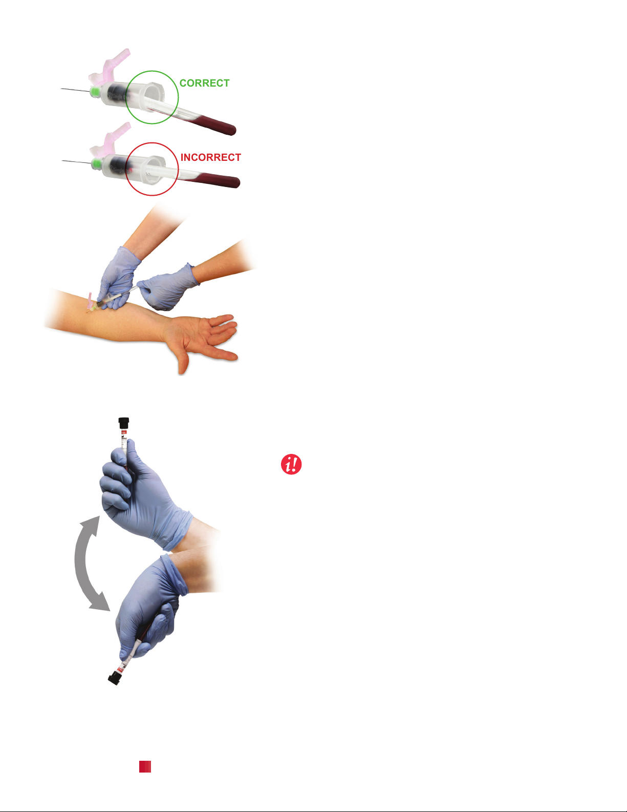
2.3 Phlebotomy Guideline
1. Insert the ESR-Vacuum Tube into the plastic holder
(Figure 5a). Hold the tube so the cap is ush against the
needle holder as the sample is collected.
2. Angle the tube so the blood stream hits the tube wall
before mixing with the citrate solution to minimize the
formation of bubbles.
3. Watch for an air bubble to rise in the sample as the tube
lls to indicate the draw is complete and remove the tube
immediately.
4. The ideal ll level and acceptable ll range are indicated
on the tube.
• 1.2ml ESR-Vacuum Tubes: 60mm ± 5mm
• 2.0ml ESR-Vacuum Tubes: 100mm ± 8mm
5. It is especially important to mix Streck ESR-Vacuum
Tubes thoroughly by inverting a minimum of 8 times due
to their smaller tube diameter and draw volumes (1.2ml
and 2.0ml) compared to an EDTA tube (Figure 5b).
6. Prior to analysis, thoroughly mix the sample again.
Rotate the tubes on the ESR-657 Mixer for a minimum
of three minutes, or hand-mix a minimum of 8 complete
inversions.
7. Samples can be maintained from the time of blood
collection for up to 72 hours prior to analysis when
transported and stored at 2-10° C, or up to 4 hours at 18-
30° C.
8. Refer to the ESR-Vacuum Tube Instructions For Use
(IFU) for more details.
Important: The mixing procedure is very
important! If the citrate is not properly mixed with
the blood, clots/aggregates may form and cause a
falsely elevated result.
2.4 Mixing a Sample
Samples must be thoroughly mixed prior to analysis. The
ESR-657 Mixer is an optional accessory designed to
accompany the ESR-Auto Plus (Figure 6). The automated
mixer holds up to 10 ESR-Vacuum Tubes at one time.
1. Place the mixer on a level surface.
2. Stop the mixer to remove or add tubes. Gently snap ESR-
Vacuum Tube samples into the numbered slots on the
mixer (Figure 6).
3. Locate the power switch on the top of the mixer to turn
the unit “on.”
4. The ESR-657 Mixer operates using a slow 360° rotation
to ensure complete mixing.
5. Allow the samples to rotate for a minimum of 3 minutes
before analyzing.
Figure 5a
Figure 5b
CORRECT
INCORRECT
Invert a
minimum
of 8 times.
ESR-Auto Plus Operator’s Manual 9
2.5 Secondary Patient Labels
The ESR-Auto Plus reads the sample using infrared light.
This light is very strong and can typically read through one
layer of most commonly used labels.
Caution must be taken when applying additional patient
labels to ESR-Vacuum Tubes. Excessive label thickness,
wrinkling or agging may increase the outer diameter of the
tube enough to wedge it in the instrument. If the operator
experiences resistance when inserting a tube containing a
secondary label, they should remove the tube before it is fully
inserted and remove the additional label before proceeding.
Secondary labels must be positioned correctly and
completely adhered to the tube surface to prevent label
fragments or label adhesive build-up in the instrument well,
which could obstruct sample analysis.
Important: Samples with a ll level outside the ll
range alarm limits will abort immediately. Refer
to section 10.1.
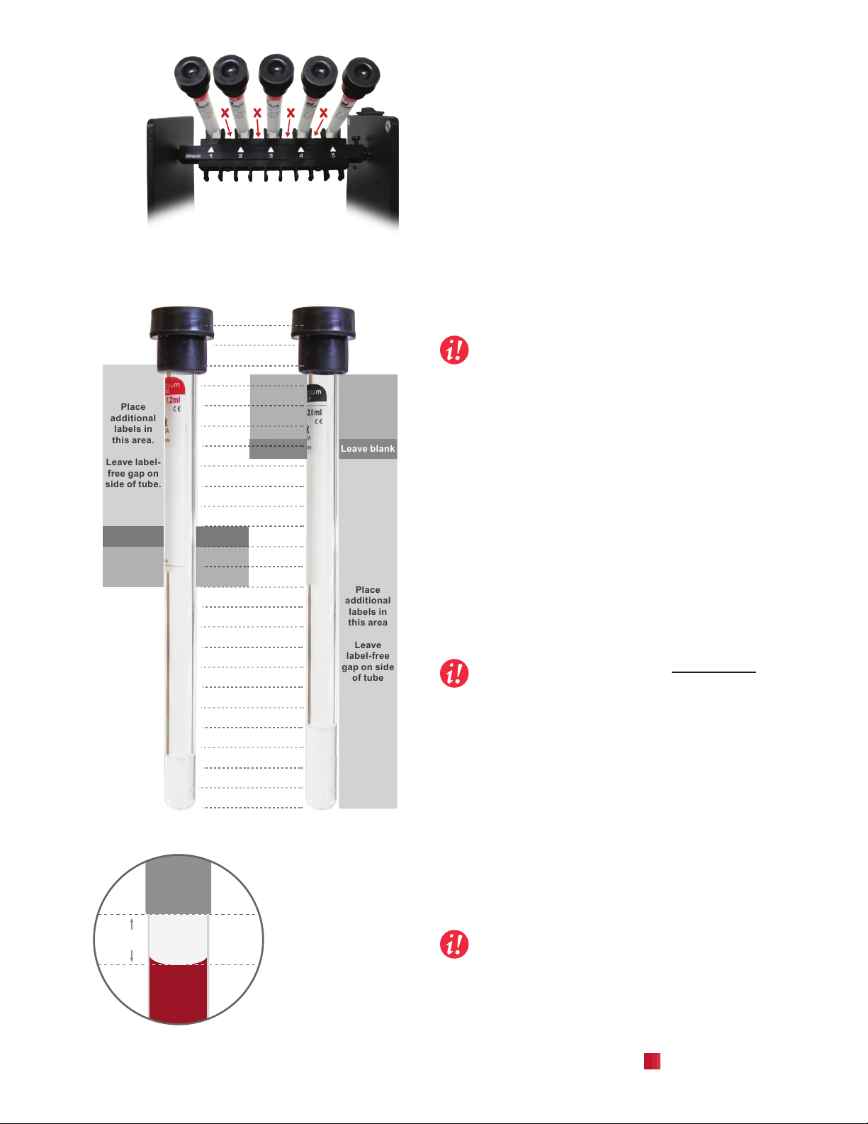
1.2ml Tubes (Figure 7a)
The 1.2ml ESR-Vacuum Tube is the primary tube used in
ESR-Auto Plus.
1. The ideal ll level of the 1.2ml tube is 60mm ± 5mm from
the bottom of the tube. The ideal ll level and range are
printed on the tube label. The ll range can extend to as
much as ± 9mm from the ll line without compromising
the integrity of the sample.
2. Additional labels should be applied facing the same
direction as the original label and as close to the cap as
possible, leaving a label-free gap on the back of the tube.
3. Insert the tube in the ESR-Auto Plus with the label facing
forward.
Important: Leave a space of at least 5mm between
the blood level in the tube and any additional
labels to ensure accurate reading of the sample
(Figure 7b).
2.0ml Tubes (Figure 7a)
The 2.0ml ESR-Vacuum Tube can be used in the ESR-Auto
Plus as long as the tube is inserted in the ESR-Auto Plus
correctly and additional labels are applied correctly.
1. The ideal ll level of the 2.0ml tube is 100mm ± 8mm.
2. Do not place additional labels above the ll level printed
at the top of the original label.
3. Place additional labels facing the same direction as the
original label, creating a label-free gap on one side of the tube.
Important: This gap is critical to allow accurate
measurement of the level of blood in the tube.
4. Insert the tube in the ESR-Auto Plus with the label facing
forward, leaving the label-free side at the rear to ensure
accurate reading of the sample.
1.2ml
tube
2.0ml
tube
Leave blank
Leave blank
Ideal ll
range
Ideal ll
range
120
110
100
90
80
70
60
50
40
30
20
10
0mm
Place
additional
labels in
this area.
Leave label-
free gap on
side of tube.
Place
additional
labels in
this area
Leave
label-free
gap on side
of tube
70
65
55
108
92
87
Figure 7a: Label Placement (to scale)
Figure 6: Correct tube placement in mixer
blood
secondary
label
blank
space
5 mm
CORRECT
blood
secondary
label
blank
space
3 mm
INCORRECT
Figure 7b: Secondary
label positioning, 1.2ml
tubes (enlarged to
show detail)

320597-3 - NOVEMBER 2016
10 ESR-Auto Plus Operator’s Manual
2.6 ESR Tube Labeling Sleeves
ESR tube labeling sleeves (Streck catalog # 240363) are
available to accommodate very long barcode labels. Such
labels may obstruct the blood column during analysis,
leading to inaccurate results. The labeling sleeves help
reduce any errors and facilitate proper patient identication.
1. Remove all 5 labeling sleeves from the sheet by folding
along the perforated edges. Separate the individual
labeling sleeves by folding along the perforated lines
between each sleeve.
2. Collect or transfer a valid blood specimen into an ESR-
Vacuum Tube.
3. Bend both sides of the labeling sleeve by creasing the
tabs along the scored lines (Figure 8a).
4. Insert the tube through the hole in the labeling sleeve with
the tabs pointing up around the rubber stopper (Figure 8b).
5. Apply the patient-specic identication label across both
tabs of the labeling sleeve (Figure 8c).
Important: The patient-specic identication
label may extend beyond the end of the labeling
sleeve, depending on the size of the patient label.
Additional identication labels placed on the
tube must be placed outside the scanning area of
the tube. Refer to Section 2.5.
Bend at scored lines
Figure 8a
Figure 8b
Figure 8c

ESR-Auto Plus Operator’s Manual 11
Figure 9a
2.7 Starting a Sample
12:00
next sample...
The ESR-Auto Plus is ready to accept a sample when
the “Next Sample” standby mode appears in the display
window. Scan the patient barcode with the barcode
scanner, or enter the sample ID code manually on the
keypad. An ID code is required to run a sample.
enter id:
12345_
An ID code may contain up to 13 digits. When manually
entering an ID code, press to delete incorrect digits and
to conrm the code. The instrument will automatically
add the signal when using the barcode scanner.
insert 12345
in free position
After the barcode is scanned or the ID code is entered,
insert the well-mixed, room temperature sample in any
free position as indicated by a green light (Figure 9a).
The position light will turn red and the ESR-Auto Plus will
initiate testing.
Important! Samples may be loaded until motor
initiates. Wait until the unit returns to standby to
continue loading samples.
Important! All samples should be properly mixed
and at room temperature before analyzing. A
sedimented sample may require several minutes
of mixing. Refer to Section 2.4.
2.8 Reporting Results
It is good laboratory practice to visually correlate the level of
sedimentation in the sample tube to the printed result. After
measurement is complete, the ESR-Auto Plus automatically
prints results on the internal printer and the DATA OUTPUT
port. The internal printer can be congured in the software.
Refer to Section 5.5.
2.9 Canceling a Sample
Important! Disturbing a sample during the
analysis period may invalidate results. If a sample
is moved during the analysis period, re-mix the
sample and restart the test from the beginning.
To cancel a sample, remove the tube from its position or
press and hold the keypad number corresponding to the
tube position. Press to abort. Aborted samples will not
be stored in the instrument log le.
– abort sample –
pos 1 aborted.
The display will show that the sample has been aborted.
The red light will change to green on the position indicator
and an ESR result will print with a blank ESR value and an
error code of 4 (Figure 9b).
********* ESR RESULT *********
YYYY-MM-DD HH:MM SERIAL NO. 506-0000
SOFTWARE VERSION: v00.0 (YYYY-MM-DD)
POS: 1 ERROR: 4 STATUS: 1
PATIENT NAME: ___________________________
PATIENT ID: 123456789
ESR: --- MM WESTERGREN (QM 1.2 ml)
ALARMS:
-SAMPLE ABORTED
Figure 9b: ESR Result Printout

Table of contents
Other Streck Laboratory Equipment manuals


Popular Laboratory Equipment manuals by other brands

Sakura
Sakura Tissue-Tek Prisma Plus operating manual

Fluke
Fluke TiR4 user manual

De La Rosa Research
De La Rosa Research 14012A user guide

Thermo Scientific
Thermo Scientific BIOShield 1000A instruction manual

Agilent Technologies
Agilent Technologies ZORBAX RRHT Series user guide

Metrohm
Metrohm 930 Compact IC Flex ChS/Deg manual


