Thermo Savant SPEEDVAC SPD Series User manual

SPEEDVAC®CONCENTRATOR
SPD-SERIES BASIC
SPD101B
INSTRUCTION MANUAL
A Thermo Electron business

Disclaimer:
All statements, information and data given herein are believed to be accurate and reliable but are presented without guarantee, or responsibility of any
kind, expressed or implied. Statements or suggestions concerning possible use of our products are made without representation that any such use is
free of patent infringement and are not recommendations to infringe any patent. The user should not assume that all safety measures are indicated, or
that other measures may not be required.
Table of Contents
Section Section Title — Overview Page
1.0 Overview of the SPD101B Unit 1
1.1 Installation of the SPD101B Unit 2
1.2 How to Hook Up the SPD101B Unit 2
Section Section Title — Control Panel Page
2.0 The Control Panel 3
2.1 Description of the Control Panel 3
Section Section Title — Pre-heat Function Page
3.0 Pre-Heat Function 4
3.1 The Manual Run 4
Section Section Title — Rotor Selection Page
4.0 Rotor Selection Guide 5
Section Section Title — Guidelines Page
5.0 Guideline for Solvent Choice 6
Section Section Title — Maintenance Page
6.0 Maintenance & Service 7
Section Section Title — Specifications Page
7.0 Specifications & Warranty 8
Appendix 1 - Additional SPD101B System Set-ups 9
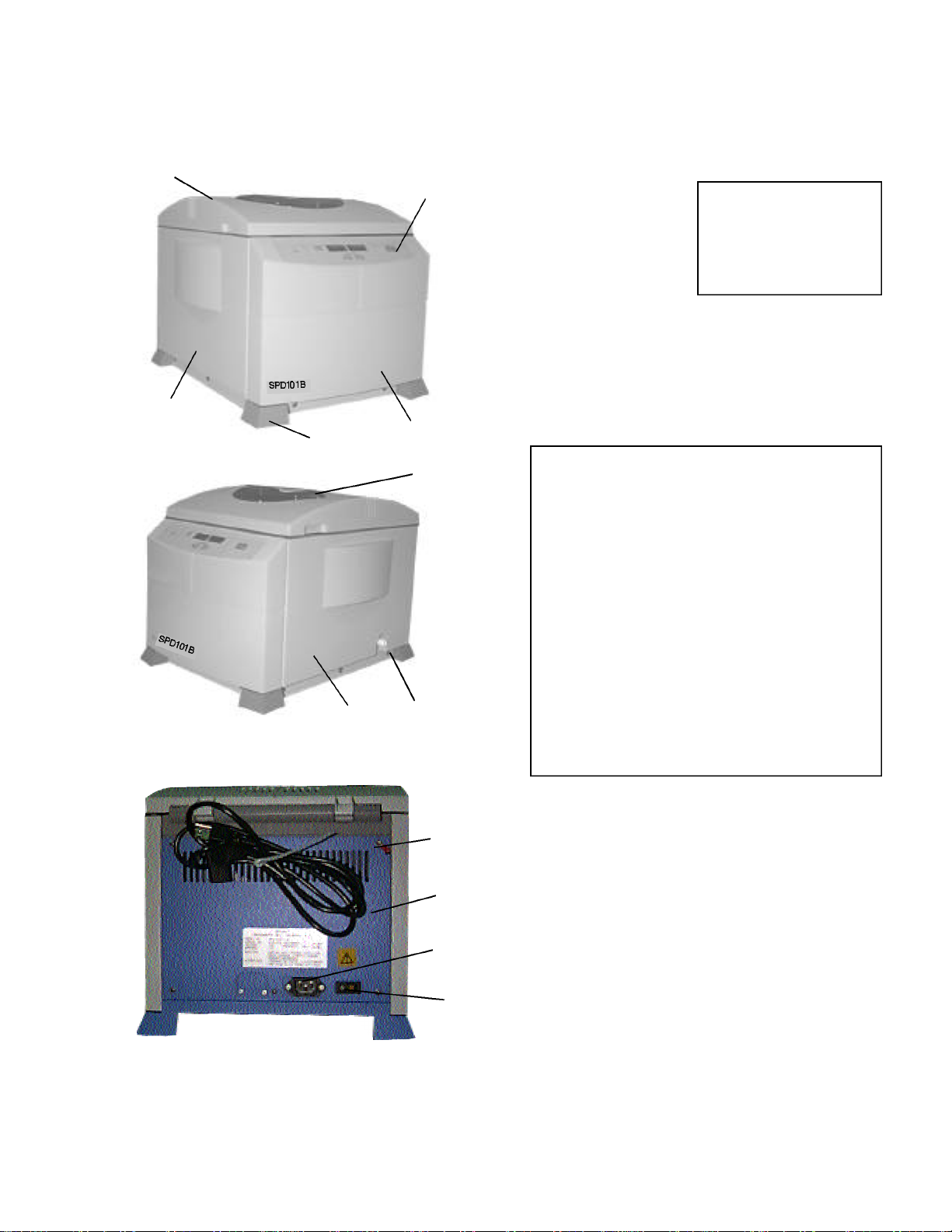
1. Top Cover
2. Control Panel
3. Front Panel
4. Left Side Panel
5. Anti Skid/Vibration
6. Right Side Panel
7. Chamber View Window
8. Vacuum Port
9. AC Socket
10. Main On/Off Switch
11. Manual Cover Lock Release
12. Rear Access Panel
12
3
45
6
12
8
9
10
11
7
Figure 1 = Front View
Figure 2 = Side View
Figure 3 = Back View
Fig. 1
Fig. 2
Fig. 3
1.1 Overview of the SPD101B Unit
1
1.1 INSTALLATION OF THE SPD101B
2
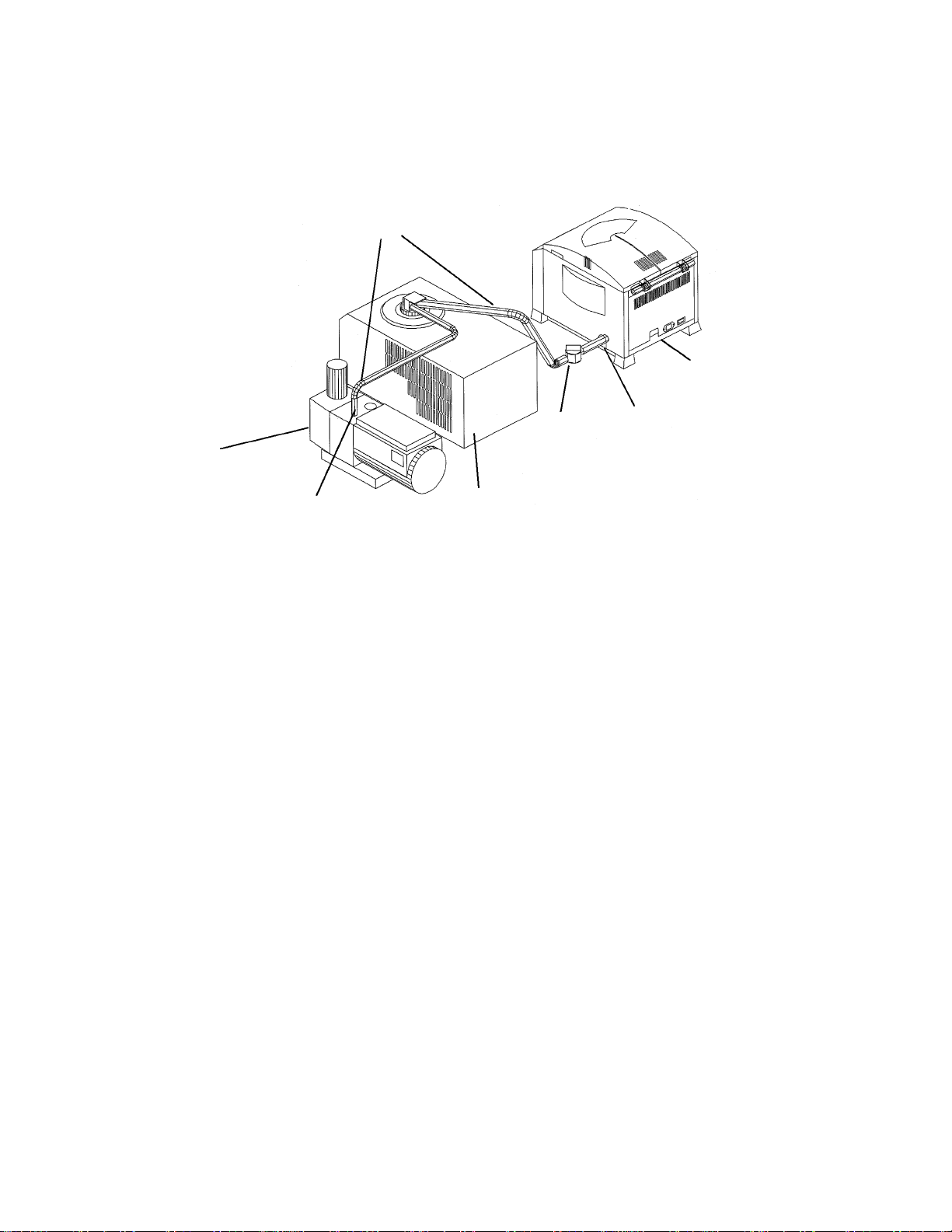
Savant
Vacuum Pump
Savant
Cold Trap
SPD101B
Manual
Bleeder
Valve
Vacuum Tubing
1. Unpack unit from box and verify all parts match packing list.
2. Read instruction manual carefully! If assistance is required, call Thermo Savant Customer
Care at 1-800-634-8886, 631-244-2929, Fax: 631-244-0606.
3. If the unit is part of a larger system, use vacuum tubing supplied to hook up unit.
(See figure 4).
4. Vacuum clamps must be put on vacuum ports of pump and SPD unit (See item 8 on figure 2,
and figure 4).
5. If being hooked up to existing system, simply attach vacuum tubing to port on side of unit.
(See item 8, figure 2-vacuum port).
CAUTION - Cold trap should be in line between vacuum source and SPD Unit.
1.2 How To Hook Up The SPD101B SpeedVac®System
Figure 4-Rear View of System
Clamp
Clamp

3
2.0 SPD101B Control Panel
1. MODIFY TEMPERATURE UP/DOWN - Modifies selected parameter.
2. RUN/STOP - Starts a manual run, Terminates a manual run.
3. VIEW - Press to view the preset parameters during the run.
4. TEMPERATURE DISPLAY (GREEN DISPLAY)- Indicates set temperature or actual
temperature during pre-heat or during a run from 45 ˚C to 80 ˚C, or “NO” heat.
5. RUN TIME DISPLAY (GREEN DISPLAY) - Indicates the time in GREEN, the timer
is counting up in 1 minute intervals to 9.59.
2.1 Description of SPD101B Control Panel
12
3
45

•Used to pre-heat chamber prior to or between runs.
•The chamber will always pre-heat to the set point on the display. (see page 3 on
how to modify setpoint temp.)
•Cover must be left closed for pre-heat function to work. If left open, no heating of
chamber will occur.
(HINT) Pre-heating the SpeedVac®chamber will shorten the sample drying time by coun -
teracting evaporative cooling of the sample. Set temperature at 35 to 45˚C and leave
cover closed.
3.1 THE MANUAL RUN SPD101B
1. Connect the unit to its required voltage.
2. Turn the power switch to ON, located on the back of the unit. The coverlock
unlocks, allowing the top cover to be opened. (RED power light is ON.)
The display lights up, showing the default values:
TEMPERATURE: 45 ˚C (GREEN)
TIME: 0.00 HRS. (GREEN)
3. Place sample tubes in rotor so load is balanced. Secure rotor with the supplied
knob (hand tight). Close cover.
4. Using the up/down keys, set temperature between 45 ˚C - 80 ˚C.
5. Press RUN/STOP button to initiate the run. (GREEN light is illuminated). The
cover locks and rotor starts spinning.
NOTE:If the cover is not closed the display will show “Lid” and the run will not
start.
6. Wait approximately 1 minute for rotor to reach speed before applying vacuum to
chamber. This will stop samples from bumping!
7. Open manual bleeder valve to apply vacuum to chamber.
8. The timer counts up in 1 minute intervals. (GREEN decimal point blinks.)
9. Temperature rises to set-point.
4
3.0 PRE-HEAT FUNCTION
5
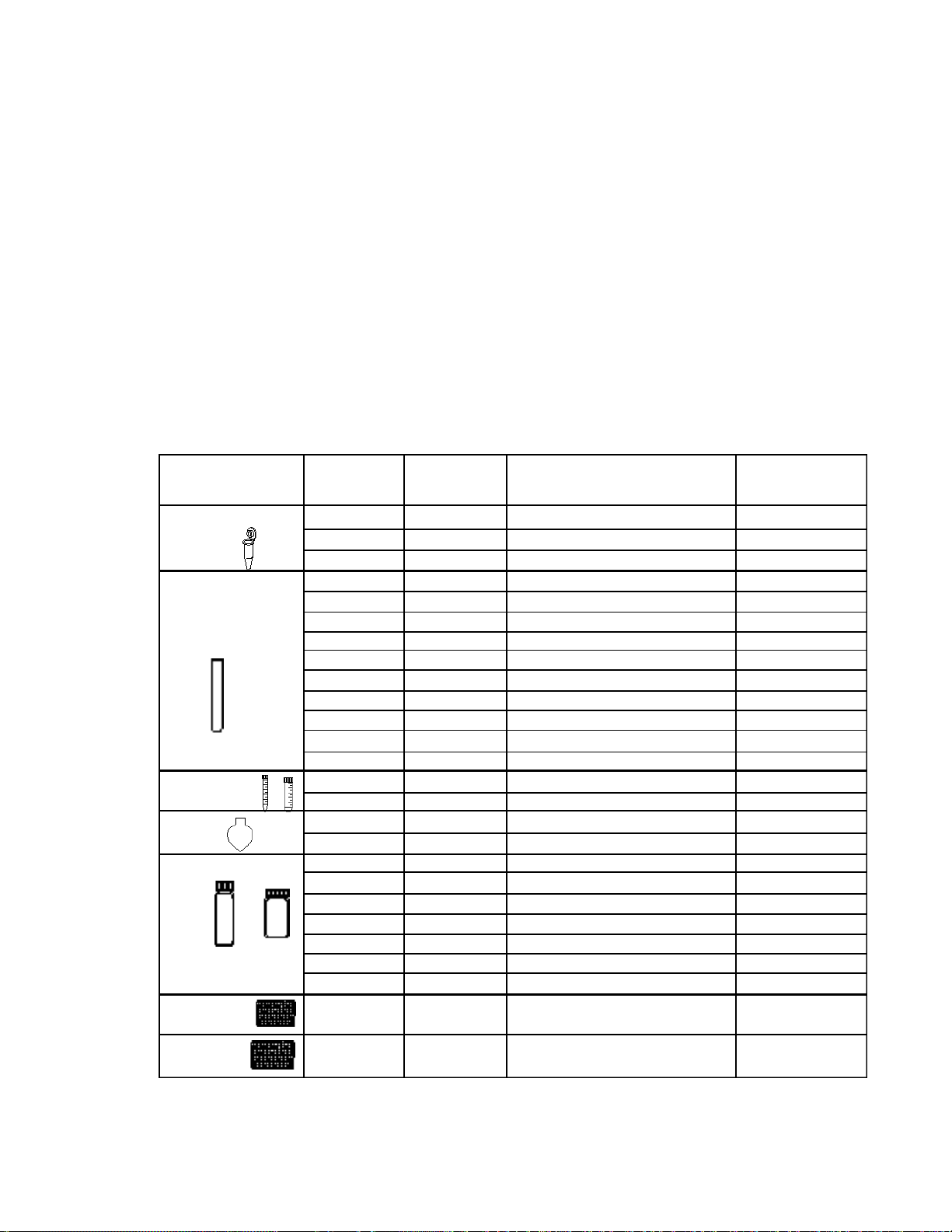
CENTRIFUGE
TUBES
4.0 ROTOR SELECTION GUIDE
Working
Volume (ml) Number
of Tubes Description Rotor
Model
RH40-11
RH64-11
RH120-11
RH100-8
RH40-6
RH100-6
RH20-12
RH40-12
RH72-12
RH20-12
RH32-13
RH8-18
RH6-18-150
RH10-15
RH6-50
RH8-50
RH4-100
RH60-12-40
RH60-12-40
RH12-20
RH24-15
RH12-20
RH24-18
RH12-28
RH2MP
RHDW2MP
1.5 - 2.0 ml
1.5 - 2.0 ml
1.5 - 2.0 ml
0.5ml (8 x 29mm)
0.4ml (6x 50mm)
0.4ml (6 x 50mm)
12 x 75mm
1.5 - 2.0 (12 x 75mm)
12 x 75mm
13 x 100mm
13 x 100mm
18 x 100mm, 17 x 95, 16 x 100
18 x 150 mm
15ml conical (16 x 120mm)
50ml conical (28 x 115mm)
50ml pear shaped flask
100ml pear shaped flask
12 x 32mm
12 x 40mm vials
20 x 47mm v-vials
1 dram vials (15 x 45mm),4ml
20 x 60mm v-vials
18 x 52mm mini-scintillation vials
28 x 60mm scintillation vials
Microplates
Deepwell Microplates
40
64
120
100
40
100
20
40
72
10
32
8
6
10
6
8
4
60
60
12
24
12
24
12
2 plates
2 plates
1.2 - 1.6
1.2 - 1.6
1.2 - 1.6
0.3
0.3
0.3
4
4
4
8
8
10
25
12
40
35
80
2
2.0
2.4
3
4
5.6
16
0.3
2.0
MICROCENTRIFUGE
TUBES
MICROTITER
PLATES(Shallow)
VIALS
GLASS AND
PLASTIC TUBES
FLASKS
DEEPWELL
PLATES
To End Run There Are 2 Steps:
10. Close manual bleeder and allow atmospheric air to bleed into the chamber.
11. To stop rotor, press RUN/STOP button, (GREEN light is OFF). Display shows
END. Once rotor stops turning, cover lock opens. The display reverts to last
set-parameters.
12. Open cover and remove samples.
NOTE: Pressing “VIEW” at anytime will allow viewing of setpoints.

6
5.0 GUIDELINES FOR SOLVENT CHOICE
*The SPD units (SPD121P and SPD111V with a radiant cover) are better suited for limited intermittent
use of the solvents listed in Part II. Use of these solvents with the SPD111V (without a radiant cover)
and SPD101B may cause the lid material to become discolored and cause potential damage. For addi-
tional technical assistance with respect to your solvent choice, please contact the Applications Support
Specialists, at Thermo Savant at 1-800-634-8886 or 631-244-2929 or Fax 631-244-0606.
Part I Solvents suited for the SPD101B unit
Ethanol
Methanol
Water
Acetonitrile
Part II Solvents NOT suited for the SPD101B unit
Methylene Chloride
Chloroform
Ethyl Acetate
Hydrochloric Acid
Trifluoroacetic Acid (TFA)
Dimethyl Sulfoxide (DMSO)
Dimethyl Fluoride (DMF)
N-Methylpyrrolidinone (NMP)
Part III All other solvents not listed above
Call our Application Scientists @ 1-800-634-8886 or 631-244-2929
to see if your solvent can be used in the SPD101B concentrator.

6.0 MAINTENANCE/SERVICE
1. Maintenance: The SpeedVac®SPD101B requires no scheduled maintenance.
2. Cleaning: The SpeedVac®SPD101B should be cleaned if solvents spill on
or inside the unit. Always clean up any spills immediately using absorbent
towels.
Always wear gloves when cleaning and dispose of paper towel in appropriate
designated refuse containers.
3. Replace chamber seal if cracked (Part number is 197-6020-00).
4. Outside of unit can be cleaned with dilute solution of soap and water.
5. For any other maintenance or service issues or service problems, please call
the Thermo Savant Service Department at: 1-800-717-5509, 631-244-6942,
Mon-Fri 8:00AM - 7:00PM E.S.T.
7

8
7.0 SPECIFICATIONS/WARRANTY
Model: SPD101B
Bleeder Valve: Manual
Temperature Range: 45 ˚C-80 ˚C
Maximum Carrier Capacity: 2 (96-deepwell plates) see chart on page 5
Dimensions: (W x D x H) in.: 14 x 18 x 13
cm: 36 x 45 x 33
Weight: lbs. (kg) 31 (14)
Power requirements: 115 VAC/60Hz, 4.0A (Part number - SPD101B-115)
230 VAC/50Hz, 2.0A (Part number - SPD101B-230)
220 VAC/60Hz, 2.0A (Part number - SPD101B-220)
All Thermo Savant products (except glassware) are warranted against defects in
material and workmanship for one year after the date of delivery to the original pur-
chaser. Thermo Savant’s warranty is limited to defective materials and workmanship,
and does not cover incidental or consequential damages. Warranty work is subject
to our inspection of the unit. No instruments, equipment, or accessories will be
accepted without a Return Material Authorization (RMA) number issued by Thermo
Savant. Costs of shipping the unit are not covered under warranty. The warranty
obliges you to follow the precautions in this manual. It is the responsibility of the user
to dispose of ALL materials in a manner in accordance with all federal, state and local
regulations. ALL RETURNED UNITS MUST BE DECONTAMINATED AND FREE OF
RADIOACTIVITY AND SHOULD BE ACCOMPANIED WITH A DECONTAMINATION
FORM. PLEASE CALL 1-800-717-5509, OR 631-244-6942 TO HAVE THIS FORM
FAXED TO YOU! Under no circumstances shall Thermo Savant be liable for dam-
ages due to the improper handling or use of its products. Thermo Savant assumes no
liability, express or implied, for use of this equipment.
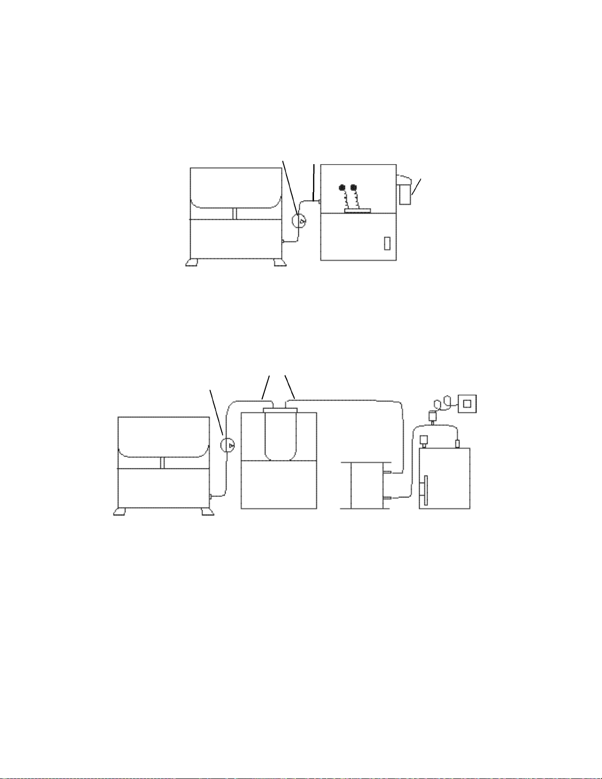
APPENDIX 1
Additional SPD101B System Set-ups
SEMI-INTEGRATED LOW VACUUM SYSTEM
SpeedVac®Concentrator
SPD101B UVS400
Universal Vacuum Source
ANT100
BV130
Bleeder Valve Vacuum
Tubing
COMPONENT HIGH VACUUM SYSTEM
BV130
Bleeder Valve
Flexible
Vacuum
Tubing
DVG50
SpeedVac®Concentrator
SPD101B RVT400
Cold Trap SCT120
Chemical Trap VLP80
Vacuum Pump
9

SPD SERIES SPEEDVAC®FAMILY
SPD101B
SPD111V
SPD121P


197-3000-00 Rev. B
©2000 Thermo Savant
100 Colin Drive • Holbrook, NY 11741-4306 USA
Tel: 631-244-2929 • 1-800-634-8886 • Fax: 631-244-0606
A Thermo Electron business
This manual suits for next models
1
Table of contents
Other Thermo Savant Laboratory Equipment manuals


Popular Laboratory Equipment manuals by other brands


Environmental Express
Environmental Express SimpleDist Operation & instruction manual

Thermo Scientific
Thermo Scientific F30400 Installation and operation manual

Collomix
Collomix VIRO neo instructions

Labnet
Labnet ENDURO GEL XL E0160 user manual

Biocontrol
Biocontrol Assurance GDS PPMX user manual

Molecular Devices
Molecular Devices ImageXpress Pico installation guide