Thermo SAFE 2010 User manual
81-09-IM.doc – Revision 4
INSTRUCTION MANUAL
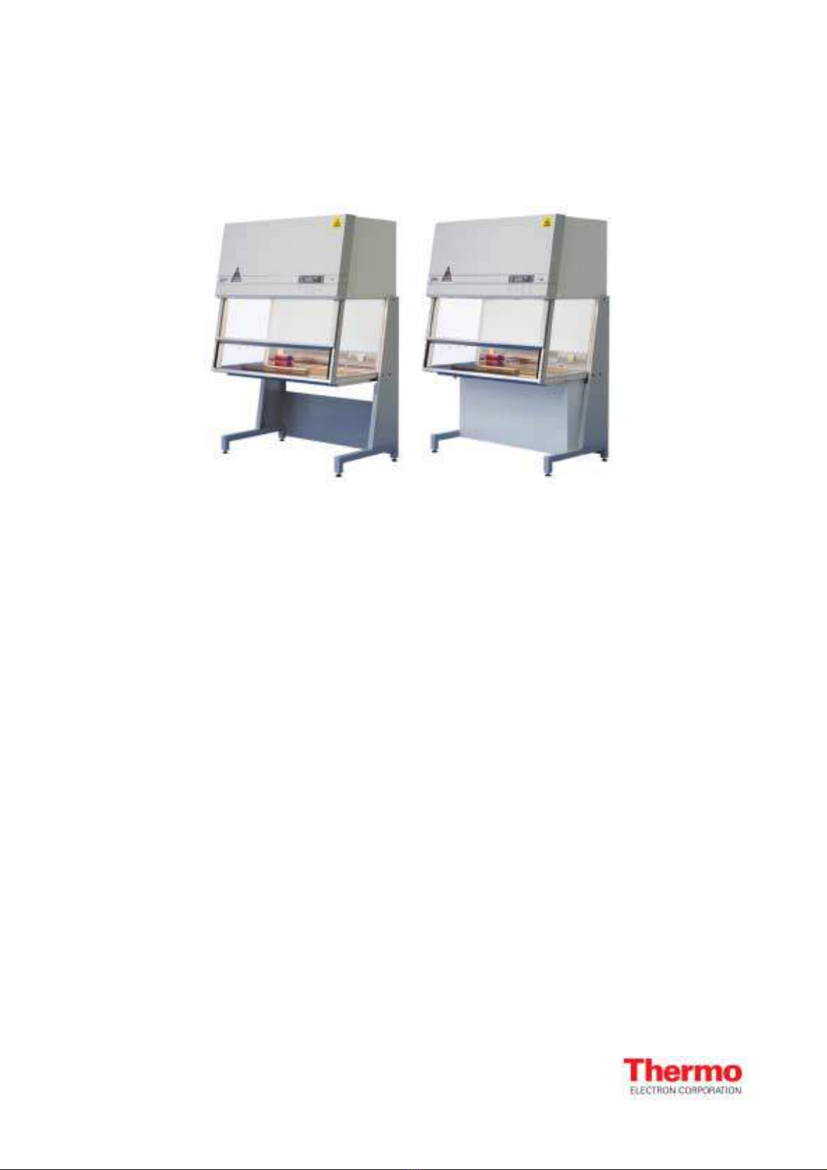
SAFE 2010 & Maxi SAFE 2010
ID 807233

Page 2 / 35 INSTRUCTION MANUAL SAFE 2010/MaxiSAFE 2010
81-09-IM.doc
Important user information
Please read this entire manual to fully understand the safe and effective use of this product.
In case you have any comments about this manual we will appreciate receiving them at the
address below.
Warranty and Liability
Jouan Nordic A/S guaranties that the product delivered has been thoroughly tested to ensure that it
meets its published specifications. The warranty included in the conditions of delivery is valid only if
the product has been installed and used in accordance with the instructions supplied by Jouan
Nordic A/S.
Jouan Nordic A/S shall in no event be liable for incidental or consequential damages, including
without limitation, lost profits, loss of income, loss of business opportunities, loss of use, and other
related exposures, caused by e.g. incorrect use of the product.
Symbols used in this manual
WARNING
Used in case of danger of a serious accident or when documentation needs to be
consulted.
.NOTE
Used to direct attention to a special item.
© Copyright 2003
Jouan Nordic A/S
Gydevang 17-19
DK-3450 Allerød
Denmark
Telephone +45 48 16 62 00
Fax +45 48 16 62 97
e-mail info.dk@thermo.com
Home page: http://www.jouannordic.com
SAFE 2010/MaxiSAFE 2010 INSTRUCTION MANUAL Page 3 of 35
81-09-IM.doc
Table of contents
1. Introduction ...................................................................................................4
2. Safety precautions ........................................................................................4
3. Description.....................................................................................................5
3.1. Working principle.............................................................................................5
3.2. Air filtration ......................................................................................................5
3.3. Air velocity monitoring .....................................................................................5
3.4. Airflow diagram................................................................................................6
3.5. Design.............................................................................................................6
4. EN 12469 approvals.......................................................................................8
5. Technical specifications...............................................................................9
5.1. Property of materials .....................................................................................11
6. Installation ...................................................................................................12
6.1. Transport through passage narrower than 900 mm. ......................................12
6.2. Preparation....................................................................................................13
6.3. Connections ..................................................................................................14
7. Testing .........................................................................................................14
7.1. Air velocity in laminar flow .............................................................................15
7.2. Air velocity in inlet and exhaust opening ........................................................15
7.3. Airflow patterns, visualisation ........................................................................16
7.4. Test of filters..................................................................................................16
7.5. Test of the retention at front opening .............................................................17
8. Work rules....................................................................................................17
8.1. Before start-up...............................................................................................17
8.2. While working ................................................................................................18
8.3. After work ......................................................................................................18
9. Control Panel...............................................................................................19
9.1. Control Panel.................................................................................................19
9.2. LCD Display ..................................................................................................20
9.3. Bar graph ......................................................................................................21
9.4. Operation ......................................................................................................21
9.5. Supervision - Alarm .......................................................................................22
10. Cleaning and decontamination...................................................................23
10.1. Daily ..............................................................................................................23
10.2. Weekly ..........................................................................................................24
10.3. Regularly .......................................................................................................24
10.4. Decontamination by use of formaldehyde......................................................24
11. Maintenance.................................................................................................26
11.1. Filters ............................................................................................................26
11.1.1. Main and exhaust filter exchange ..................................................................26
11.1.2. Procedure for replacement of main filter ........................................................27
11.1.3. Procedure for replacement of exhaust filter ...................................................28
11.1.4. Pre-filter (MaxiSAFE Only) ............................................................................29
11.2. Part list for filter .............................................................................................29
11.3. Activated charcoal filters (Optional equipment)..............................................30
11.4. Fuses ............................................................................................................31
11.5. Fluorescent light tube ....................................................................................32
11.6. Starter ...........................................................................................................33
11.7. Electrical spare parts .....................................................................................33
12. Logbook.......................................................................................................34
13. Statement.....................................................................................................35
Enclosure: Declaration of conformity
Page 4 / 35 INSTRUCTION MANUAL SAFE 2010/MaxiSAFE 2010
81-09-IM.doc
1. Introduction
You are now in possession of a high quality microprocessor-controlled Class II cabinet, Holten
SAFE 2010/MaxiSAFE 2010, designed to provide protection of the operator, the environment, and
the processed product against particle-/microbiological contamination.
The cabinet complies with the requirements stipulated in EN 12469 for SAFE 2010 and DIN 12980
for MaxiSAFE 2010. In chapter 4 you can see the options and sizes of approved cabinets.
•The Holten SAFE 2010/MaxiSAFE 2010 Class II cabinet is/has:
•Microprocessor controller with.
•LCD display indicating fan and alarm status.
•Air velocity (filter service) indicator.
•Clock (7 days) and hour-counter.
•Pre-setting of automatic start-up and UV–timer.
•Alarm for any deviation from safety conditions.
•Ergonomically correct sloping front for maximum operator comfort.
•Motor-driven, double-function front window, with both sliding and hinged modes.
•Side windows, for perfect light conditions and view to the surroundings.
•Negative pressure plenum for highest operator and product safety.
•Key switch to prevent unauthorised starting and stopping of the fan.
•Adjustable FAN speeds. Gives you the opportunity to select FAN off, reduced, or normal air
velocity.
2. Safety precautions
•To avoid unintended or improper operation of the cabinet, please carefully read this manual.
•Also, please pay attention to the short form operating instructions on the label stuck on the
cabinet.
•If you have questions related to the function or control of the cabinet or wish to order spare
parts, please always indicate type and production number from the nameplate on the right
side of the cabinet.
WARNING
The proper function and safety of the cabinet are only secured if personnel
authorised by us to do so perform the required tests, maintenance and repair work.
Please also refer to sections ”Testing” and ”Maintenance”.
The following precautions must be taken for operation of the Holten SAFE 2010/
MaxiSAFE 2010.
SAFE 2010/MaxiSAFE 2010 INSTRUCTION MANUAL Page 5 of 35
81-09-IM.doc
WARNING
The safety cabinet must not be used for Group 4 pathogens.
Attention is drawn to the risk assessment requirements of the Control of Substances Hazardous to
Health (COSHH) Regulations 1999. (UK).
WARNING
The cabinet is not suitable for HIGH-RISK biological agents.
HIGH RISK biological agents include all etiologic agents designated Class 4 by CDC, and
oncogenic viruses classed high risk by NCI. (USA).
WARNING
Never operate the Holten SAFE 2010/MaxiSAFE 2010 cabinet if the fan
compartment cover is removed.
If this cover is removed, the cabinet will give no protection of the operator or the environment and
the fan will run with openly rotating blades.
WARNING
The Holten SAFE 2010/MaxiSAFE 2010 Class II cabinet will not provide any
protection for operator or environment against harmful gases or vapours.
WARNING
Always keep your hands out of the work chamber before starting the sliding
window.
The airspeed monitoring system needs approximately 5 minutes to warm up and stabilise after the
fan has been switched on.
3. Description
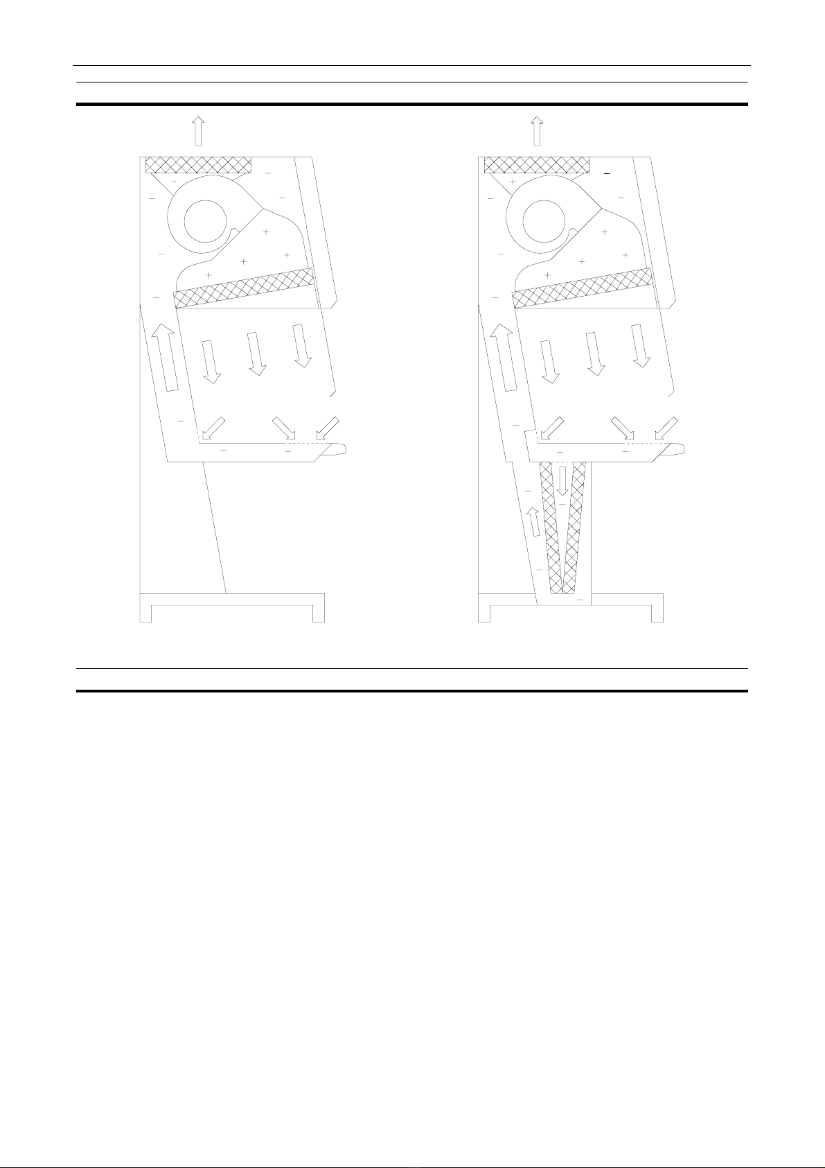
3.1. Working principle
The microbiologic safety cabinet is a modified exhaust cabinet with a turbulence-free (laminar)
vertical displacement flow of clean air in the work chamber protecting the product against particle
contamination. During operation the front window is partly open and the in-going airflow prevents
the escape of particles from the inside of the work chamber thus protecting the operator and the
environment.
3.2. Air filtration
The MaxiSAFE 2010 pre-filter and the main filter and exhaust filter of SAFE 2010/MaxiSAFE 2010
are all high-efficiency HEPA filters.
3.3. Air velocity monitoring
The low turbulence vertical flow and the exhaust flow are monitored by means of air velocity
sensors. Any deviation from safe conditions will be indicated optically and acoustically.
Page 6 / 35 INSTRUCTION MANUAL SAFE 2010/MaxiSAFE 2010
81-09-IM.doc
3.4. Airflow diagram
Figure Fejl! Ukendt argument for parameter..
SAFE 2010 Figure Fejl! Ukendt argument for parameter..
MaxiSAFE 2010
3.5. Design
The safety cabinet consists of:
•Fan and filter compartment and return air duct (double back wall) made of polyester coated
sheet steel.
•Support stand made of polyester coated sheet steel and equipped with levelling feet.
•Work chamber with tabletop and trough in stainless steel (AISI 304).
•Side windows and sliding front window all in safety glass.
•Internal ventilation system with negative pressure plenum.
•Microprocessor control and supervision system.
The work chamber is formed by the ceiling (main HEPA filter), side windows, back wall with
installation zones, tabletop and trough; the front is partly closed by the double-action, sliding front
window; the work opening is situated below the front window.
•The outlet opening of the main HEPA filter cover the entire ceiling surface thus giving an
extremely uniform airflow.

SAFE 2010/MaxiSAFE 2010 INSTRUCTION MANUAL Page 7 of 35
81-09-IM.doc
•The trough will collect and hold any spillage of fluids. A drain valve can be installed
(Standard on MaxiSAFE 2010).
•The installation zones in the back wall can be equipped with electric outlets and a UV-light
fixture.
•The side windows come with holes for installation of valves.
•The stainless steel modular tabletop is easily removed for cleaning.
•The internal light is installed on the front of the work chamber outside the front window. This
secures that the light is glare-free and will cause neither turbulence nor unwanted heating
inside the work chamber.
•Arm rest for air intake efficiency.
Options:
•UV light integrated in the back wall behind a small door.
•Protective ground sockets 230V ∼/ 4A installed in the back wall.
•Valves for various gasses i.e. gas, nitrogen (N2) vacuum, or Carbon dioxide (CO2), a
maximum of 3 installed in each side window.
•Exhaust valve for connection to the exhaust system – consult your dealer for detailed
information.
•Double HEPA-filter exhaust system as specified by BS 5726-(92).
Please contact our sales department for information regarding other available options.
Page 8 / 35 INSTRUCTION MANUAL SAFE 2010/MaxiSAFE 2010
81-09-IM.doc
4. EN 12469 approvals
The SAFE and MaxiSAFE 2010 1.2, 1.5 and 1.5 are approved in different configurations.
The table shows the type and the options:
Approved options for Microbiological Safety cabinets
Maximum 2 electrical outlets in each side
Maximum 3 gas valves in each side window
Alternative filter Camfil H14
UV light
Battery back-up
Multiple processing relay
Cabinet without support stands (Table model)
Only SAFE
Support stand table model
Elevation stand table height 70 – 100 cm
Support stand low 76 - 80 cm ± 2 cm
Support stand high 88 - 92 cm ± 2 cm
Single module table top
2 module table top in the centre
Only SAFE / MaxiSAFE 1.2 and 1.8
3 module tabletop in the centre
Only SAFE / MaxiSAFE 1.5
4 module tabletop in the centre
Only SAFE / MaxiSAFE 1.2 and 1.8
5 module tabletop
Only SAFE / MaxiSAFE 1.5
Stainless steel back wall / sides
Weighting top of marble
Drain valve
Standard on MaxiSAFE
Magnetic valve
Foot contact

SAFE 2010/MaxiSAFE 2010 INSTRUCTION MANUAL Page 9 of 35
81-09-IM.doc
5. Technical specifications
All parts of the cabinet which has a negative pressure is tested in accordance with EN 12469:2000 Annex B,
and meet the LI-C level.
Model 0.9 SAFE MaxiSAFE
External dimensions, DxWxH mm 895x1040x2000
Chamber dimensions, DxWxH mm 580x900x725/650
Weight, kg 200 225
Spillage, litres 13.5 4.5
Exhaust volume, m3/h ±10 % 300
Air velocity in-flow, m/s ≥0.4
Air velocity down-flow, m/s ±20 % 0.4
Noise level, DIN dB(A); EN ISO 3744 55 57
Light intensity, Lux >1200
Supply Voltage/frequency, Volts/Hz 230/50
Power consumption, Watts 500
Required fusing Fuse T16A or circuit breaker 16A
Input current, A 1.6
Socket outlet(s), Volts/Hz/Amps 230/50/4
Maximum leakage current, mA 0.7
Model 1.2 SAFE MaxiSAFE
External dimensions, DxWxH mm 895x1340x2000
Chamber dimensions, DxWxH mm 580x1200x725/650
Weight, kg 225 250
Spillage, litres 18 6
Exhaust volume, m3/h ±10 % 400
Air velocity in-flow, m/s ≥0.4
Air velocity down-flow, m/s ±20 % 0.4
Noise level, DIN dB(A); EN ISO 3744 57 59
Light intensity, Lux >1200
Supply Voltage/frequency, Volts/Hz 230/50
Power consumption, Watts 600
Required fusing Fuse T16A or circuit breaker 16A
Input current, A 1.8
Socket outlet(s), Volts/Hz/Amps 230/50/4
Maximum leakage current, mA 0.7
Page 10 / 35 INSTRUCTION MANUAL SAFE 2010/MaxiSAFE 2010
81-09-IM.doc
Model 1.5 SAFE MaxiSAFE
External dimensions, DxWxH mm 895x1640x2000
Chamber dimensions, DxWxH mm 580x1500x725/650
Weight, kg 270 315
Spillage, litres 22.5 7.5
Exhaust volume, m3/h ±10 % 500
Air velocity in-flow, m/s ≥0.4
Air velocity down-flow, m/s ±20 % 0.4
Noise level, DIN dB(A); EN ISO 3744 58 59
Light intensity, Lux >1200
Supply Voltage/frequency, Volts/Hz 230/50
Power consumption, Watts 700
Required fusing Fuse T16A or circuit breaker 16A
Input current, A 2.6
Socket outlet(s), Volts/Hz/Amps 230/50/4
Maximum leakage current, mA 0.7
Model 1.8 SAFE MaxiSAFE
External dimensions, DxWxH mm 895x1940x2000
Chamber dimensions, DxWxH mm 580x1800x725/650
Weight, kg 300 355
Spillage, litres 27 9
Exhaust volume, m3/h ±10 % 600
Air velocity in-flow, m/s ≥0.4
Air velocity down-flow, m/s ±20 % 0.4
Noise level, DIN dB(A); EN ISO 3744 58 59
Light intensity, Lux >1200
Supply Voltage/frequency, Volts/Hz 230/50
Power consumption, Watts 800
Required fusing Fuse T16A or circuit breaker 16A
Input current, A 3.0
Socket outlet(s), Volts/Hz/Amps 230/50/4
Maximum leakage current, mA 0.7

SAFE 2010/MaxiSAFE 2010 INSTRUCTION MANUAL Page 11 of 35
81-09-IM.doc
5.1. Property of materials
Units Material Treatment
Front and side windows Safety glass Laminated/tempered
Front window frame Stainless steel AISI 304 Polished
Side window frame PVC
Support stand Steel 1203 2 mm Polyester-coated RAL 7038
Front shield Al Mg 3, 2 mm Polyester-coated RAL 7038
All other painted parts Steel 1203, 1.5 mm Polyester-coated RAL 9002
Trough and tabletop Stainless steel AISI 304 Polished
Internal main and exhaust plenum Polystyrene
Page 12 / 35 INSTRUCTION MANUAL SAFE 2010/MaxiSAFE 2010
81-09-IM.doc
6. Installation
Transport of the SAFE 2010/MaxiSAFE 2010 can be carried out by lifting the cabinet using a forklift
either sideways under the support stand or directly under the trough. Furthermore the cabinet can
be moved manually by using hooks in the dedicated holes in the support stand.
WARNING
Whenever transportation of the cabinet is needed, precautions should be taken to
prevent it from overturning due to the high-located mass centre.
WARNING
In order to prevent damage to the cabinet it must be handled as fragile goods.
Storage of the cabinet must be in an environment of maximum 80 % relative humidity and at
temperatures between 5 °C to 50 °C.
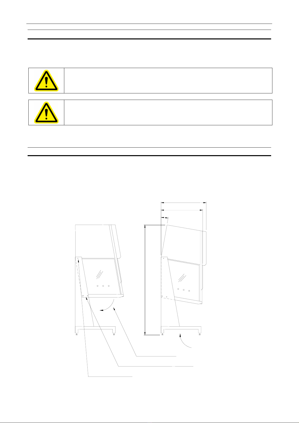
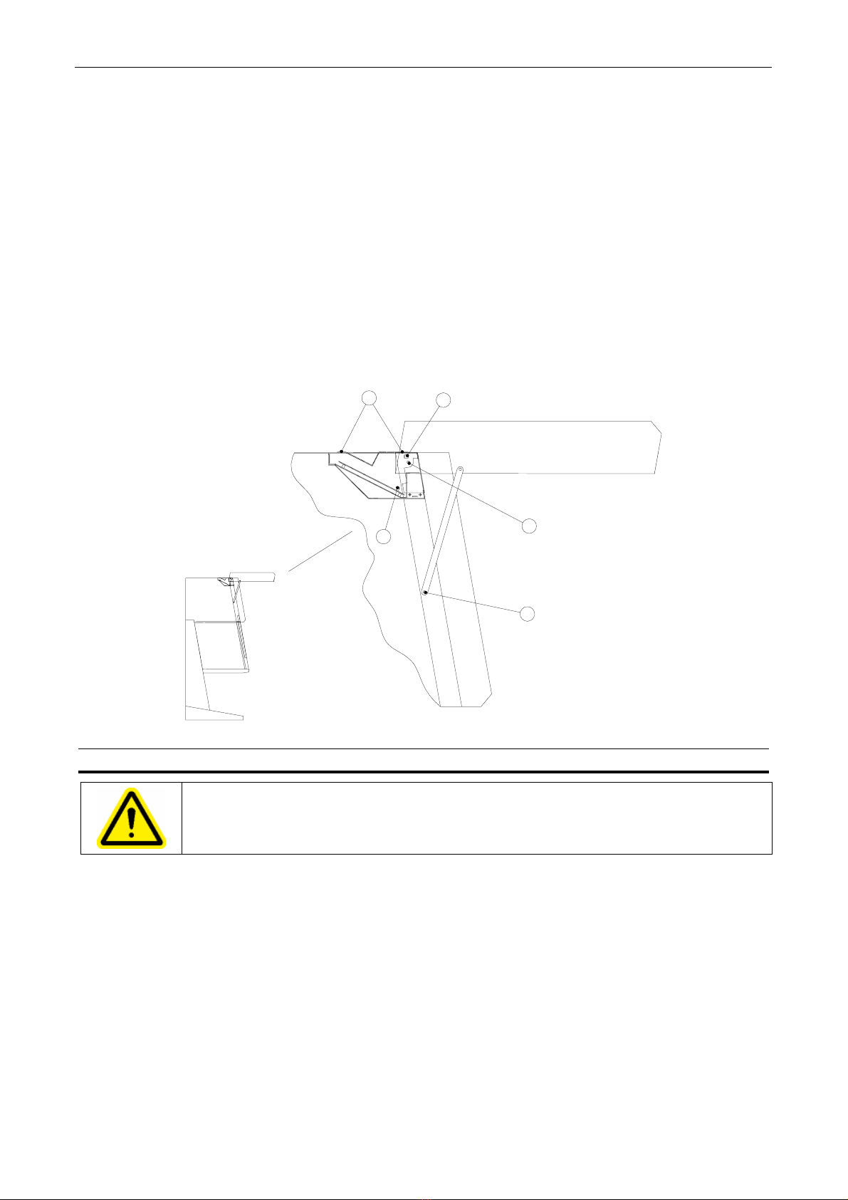
6.1. Transport through passage narrower than 900 mm.
The cabinet may be tilted 10 °, see figure 3 so that the sloping front is in vertical position. If the
passage is narrower than 850 mm you may dismount the front shield with the control panel and the
bracket holding the mains plug on the back of the cabinet, see figure 4.
The cabinet can then be moved through a standard 800 mm wide door.
Space for forklift.
1. Loosen the screw.
2. Screw off and remove the two screws.
3. Tilt the cabinet 10°.
2000 (low support stand)
2110 (high support stand)
850
795
10°
Figure Fejl! Ukendt argument for parameter..How to tilt the cabinet.
SAFE 2010/MaxiSAFE 2010 INSTRUCTION MANUAL Page 13 of 35
81-09-IM.doc
1. Bring the front window to the lowest position.
2. Disconnect the power.
3. Remove the protective cover from the fuses (4 screws) - position 1 figure 4.
4. Pull out the plug - position 2 figure 4 - for the flat cable for the display PCB on the control
PCB.
5. Disconnect the protective earth wire - position 3 figure 4.
6. Unscrew the screws for the gas spring - position 4 figure 4.
7. Unscrew the screws for the front shield - position 5 figure 4.
8. Remount the front shield in the reverse order, and continue with section 6.2 step 1 below:
1
2
3
4
5
Figure Fejl! Ukendt argument for parameter..How to dismount the front shield.
6.2. Preparation
WARNING
The installation site for the unit must be draught-free and should be selected so that
frequent passing of people in front of the work opening is avoided.
1. The tabletops of stainless steel are mounted over the trough.
2. Adjust the levelling screws to assure that the tabletop is in horizontal position and levelled.
3. Valves for gases or vacuum are installed in the side windows. A qualified technician must
make the connections for the supply.
4. For connection of the exhaust air to the exhaust air systems, special precautions which must
be discussed with the cabinet supplier, must be taken.
5. The armrest has to be mounted over the perforated holes.

Page 14 / 35 INSTRUCTION MANUAL SAFE 2010/MaxiSAFE 2010
81-09-IM.doc
When the cabinet has been installed:
1. Check that the front window is in the correct position, i.e. parallel to the front shield.
2. Never lift the front window manually, as this will cause the safety latch to engage.
3. Check that the window slides from top to bottom without any irregular sound.
4. If the window does not move when the UP or DOWN button is pressed, authorised service
personnel must be called to correct the fault.
5. Always keep hands and arms away from the working chamber when activating the front
window.
6.3. Connections
Required fusing: Circuit breaker 16 A or fuse T 16 A.
In addition, the applicable safety requirements of the local power Supply Company shall apply.
WARNING
If an automatic relay for disconnection of power in case of electric fault is needed, it
must be installed in the supply, as it is not built-in.
WARNING
Before connecting the power supply it must be checked that the mains
specifications correspond to those stated on the type plate.
WARNING
The safety cabinet is provided with a flexible power cord. The connection may be
installed hard-wired or by means of a wall outlet with protective ground.
If a hard-wired connection is used, a main switch, which will cut off all poles to the unit, must be
used. This switch must be lockable both in the ON and OFF positions.
If the unit is connected through a protective-ground wall outlet, the connector has the all-pole
insulator function. The wall outlet is to be installed out of reach of operators and may only be
accessible to authorised personnel.
7. Testing
Perform tests after installation or change of location and before the initial start-up.
WARNING
According to the standard EN 12469 and DIN 12980, the following must be tested:
•Check that manufacturer’s specifications are met.
•Air velocity in laminar flow.
•Leakage test of the main and exhaust air filter.
•Air inlet speed in the work opening.
•Check airflow patterns.
•Optionally a KI-Discus test for testing operator protection on site.

SAFE 2010/MaxiSAFE 2010 INSTRUCTION MANUAL Page 15 of 35
81-09-IM.doc
All tests have to be done by an authorised test technician.
The test results must be entered in a test book.
For more information about testing please consult the service manual.
7.1. Air velocity in laminar flow
Equipment:
The down flow is measured with a calibrated thermo anemometer.
Procedure:
Turn on the cabinet and wait until the airflow has been stabilised.
The thermo anemometer is placed in the measuring spot in a height 50 mm over the upper edge of
the front opening.
The measuring spots are the same at both SAFE and MaxiSAFE.
Measure in 2 rows 150 mm and 350 mm from the sucking holes in the front of the working plate,
starting 150 mm from the left side window and with 300 mm between the measuring spots.
On the left side of the working plate the measuring probe shall point left parallel to the back wall,
and on the right side of the working plate the measuring probe point right parallel to the back wall.
Each point is to be measured in at least 5 sec. and the value is to be recorded.
Calculate the mean value; record it as well as the maximum and minimum airflow.
Acceptance:
Mean downflow 0.40 m/s ± 10 %.
Distribution: All velocities between mean ± 20 % m/s.
Alarms:
The alarms for high and low downflow are set to mean ± 20 % m/s, and the matching voltage is to
be recorded.
7.2. Air velocity in inlet and exhaust opening
Equipment:
The inflow is measured with a suitable volumetric measuring device.
Procedure:
The measuring can take place directly in the opening or directly at the exhaust filter.
Cover the front opening with a plate and seal it so only an opening for the measuring device is free.
Measure the volumetric flow and calculate it into velocity in m/s, and record the result.
Formula for the calculation: X m3/h / (3600s/h x aperture in m2) = Y m/s.

Page 16 / 35 INSTRUCTION MANUAL SAFE 2010/MaxiSAFE 2010
81-09-IM.doc
Acceptance:
Air velocity in inlet ≥0,4 m/s.
S/MS 0,9 S/MS 1,2 S/MS 1,5 S/MS 1,8
0,4 m/s = 258 m3/h 344 m3/h 430 m3/h 516 m3/h
Alarms:
The alarm for inflow velocity is set to 0,4 m/sec, and the matching voltage is to be recorded.
The acoustic alarm is tested in accordance with DIN EN 457, measured 0.5 m from the middle of
the cabinet 1.5 m over the floor. The alarm signal must be at least 13 db(A) higher at 4000 Hz than
the sound of the cabinet.
7.3. Airflow patterns, visualisation
The purpose of the test is to verify that no smoke escapes from the working space to the room, and
that smoke will be drawn into the working space from the room.
Equipment: Smoke stick.
Procedure:
Pass the smoke stick in an easy movement along the front opening outside the cabinet. The
smoke must be drawn into the cabinet without visible turbulence.
Test the laminarity of the downflow and along the side- and back wall. No smoke must come out in
the room and only small turbulence must be observed.
7.4. Test of filters
Equipment:
Aerosol generator capable of producing test aerosol for HEPA filter leak testing. Aerosol
photometer with an upper measuring threshold of 10 ųg/l to 100 ųg/l and a range covering not less
than 5 log rates.
Test aerosol: POA (Poly-Alpha Olefin).
Emery 3004 from Henkel Company or an equivalent material.
Procedure:
Main- and exhaust filter:
Turn on the cabinet and induce the aerosol through the “challenge” valve to the upstream side of
the filter.
Scan the downstream side of the filter over the entire surface. Scan all filter joints and sealant for
leaks.
Pre-filters (Maxi):
Turn on the cabinet in reduced speed mode, and let the airflow stabilise. Remove the tabletop.
Cover half of the pre filters. Adjust the concentration over the “challenge” piece to 0. Every single
pre-filter is “challenged” with test aerosol, and all joints and surfaces are tested.

SAFE 2010/MaxiSAFE 2010 INSTRUCTION MANUAL Page 17 of 35
81-09-IM.doc
Acceptance:
Maximum local penetration: 0.01 % of upstream concentration.
7.5. Test of the retention at front opening
General:
This test is optional, but useful for determination of the operator protection after installation where
the cabinet is under influence of the laboratory environment.
Equipment:
KI – Discus tester, equipment that with an aerosol challenges the air curtain, established by the
down- and inflow.
Procedure:
With a spinning disc the test aerosol (Potassiumiodide 1.5 % in Ethanol) is spread inside the
cabinet, in a homogeneous aerosol cloud. The particles leave the disc in a horizontal course, and
try to pass the air curtain.
A sucking head with a filter inside, catches particles which pass the air curtain,. With a developing
agent (Palladiumchloride 0.1 %) passing particles will shows up as brown spots. The amount of
spots is to be counted.
Acceptance: Apf ≥1x10⁵.
8. Work rules
8.1. Before start-up
•The cabinets may only be operated at temperatures between 15 °C and 35 °C, at maximum
80 % relative humidity, and at normal air pressure.
•All cabinets are developed and produced for use in clean environments.
•They must not be operated outdoors or in environments with extreme air pollution. The safety
cabinets are not intended to filter vapours containing acids or organic solvents. The safety
cabinets must not be used as a fume hood.
•Approximately 15 minutes before any work in the cabinet, the fan of the unit must be
switched on at normal velocity. The work chamber and the front- and side windows are to be
carefully cleaned and disinfected. Use an ethanol solution or similar. It is recommended to
use special lint-free material. Do not use explosive disinfectants. See also section Fejl!
Ukendt argument for parameter..
•Objects and appliances must be carefully cleaned or disinfected before being introduced into
the work chamber. Do not bring in writing utensils, packing material, etc.
•The front window and the armrest is positioned in working position and kept in that position
during the entire work process.
•Necessary appliances for use during work must be placed within easy reach.
•Secures the appropriate protection of the operator as well as the product (e.g. clothes,
gloves, etc.).
Page 18 / 35 INSTRUCTION MANUAL SAFE 2010/MaxiSAFE 2010
81-09-IM.doc
8.2. While working
WARNING
Important for work with environmentally harmful substances!
•Do not perform work while the fan is running at reduced speed.
•The front window must be in work position during working hours.
•Place the product behind the perforated area of the work surface.
•Work with calm, smooth movements.
•Never overload the work chamber, reduce the number of transfers into and out of the work
chamber.
•Avoid products or agents with high heat emission.
•Avoid a cabinet location where personnel frequently pass and avoid draughts.
WARNING
The efficiency of the laminar airflow in the work chamber is essential for personnel
and product protection. Negative influences of the flow conditions must therefore be
avoided. They primarily arise due to:
•Rapid movements of the operator’s hand, arm, or body both in and in front of the work
chamber.
•Covered vents in the tabletop of the worktable or covered vents at the bottom of the work
chamber back wall.
•Large objects and apparatus.
•Devices making rapid movements e.g. agitators, centrifuges.
WARNING
Do not damage the main filter in the ceiling of the work chamber by mechanical
objects or heat sources, otherwise the microbiological safety is no longer ensured.
The acoustic and optical monitoring devices of the fan and front window must not be deactivated.
The enclosed armrest has to be used in order not to cover the perforated holes.
Devices developing strong heat, e.g. burners. If burners cannot be avoided, use safety burners.
Operate heat sources only with the cabinet fan activated.
8.3. After work
•Remove objects and appliances from the work chamber.
•Clean the work chamber, remove fluids, if any, from the trough and dry it. Disinfect if
required.
•Leave the cabinet fan in operation for about another 10 minutes.
•Close the front window to its lowest position.
SAFE 2010/MaxiSAFE 2010 INSTRUCTION MANUAL Page 19 of 35
81-09-IM.doc
9. Control Panel
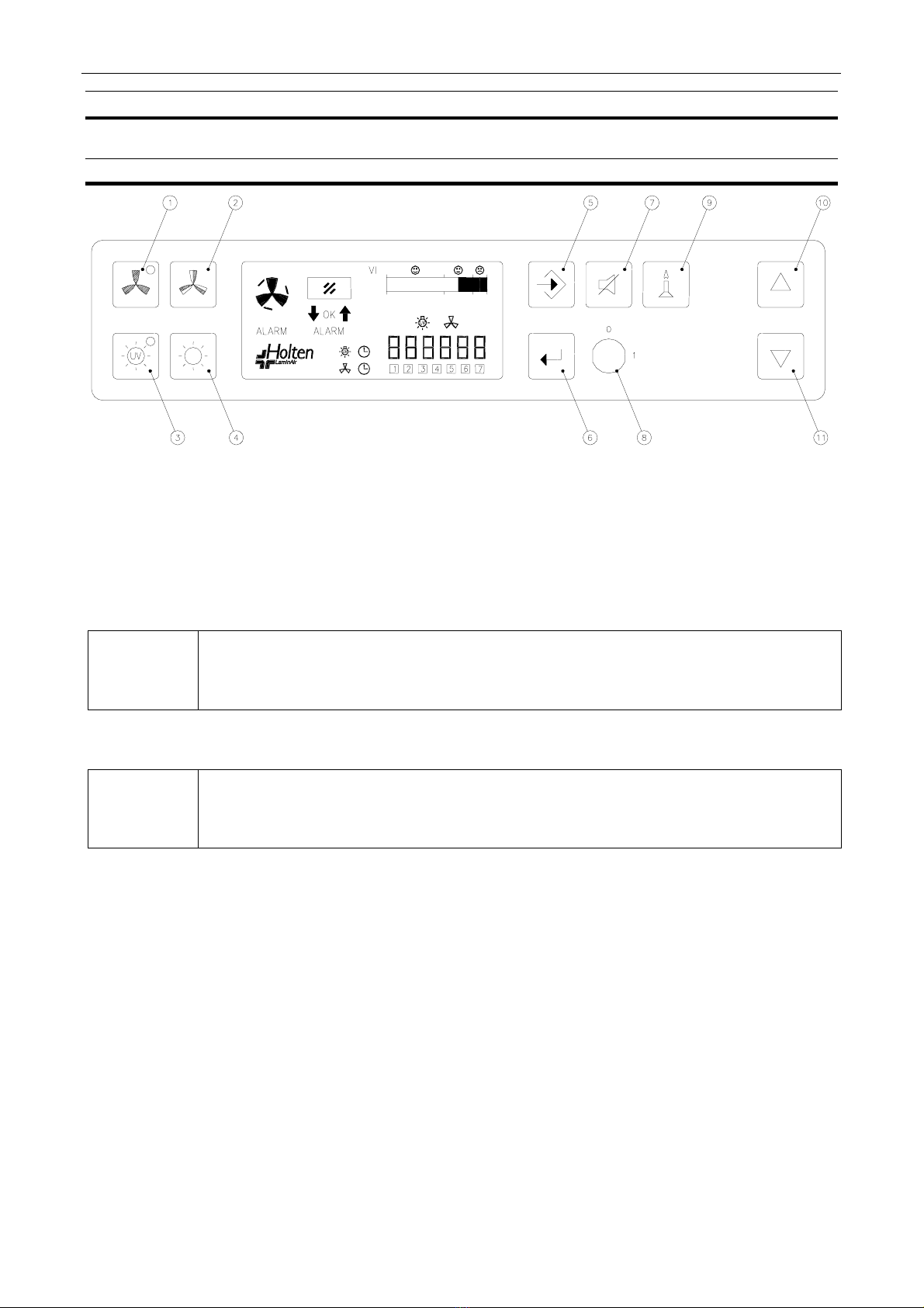
9.1. Control Panel
1. Button with green LED light to select the fan ON/OFF at normal velocity. The green light
indicates that the fan is running at normal velocity, and that conditions are safe.
2. Button to select the fan ON/OFF at reduced velocity.
3. Button with yellow LED light to select UV light ON/OFF. The yellow light indicates that the UV
light is ON. (UV light and matching UV timer for radiation time is optional).
.
NOTE
For increased safety against unintended UV radiation which will harm eyes and
skin: the front window must be closed in the lowest position and normal light must
be switched off before UV light can be switched on.
4. Button for normal light ON/OFF.
.
NOTE
For increased safety reduced velocity will turn the light OFF. When the light is
switched ON at reduced velocity the fan will be forced to normal velocity.
5. Button for programming the clock, automatic start up or the UV timer.
6. Button for entering data.
7. Button to silence the acoustic alarm. The alarm cannot be muted while cabinet is in operation
mode.
NB! Muting of the alarm is possible on the DIN 12950 approved cabinets.
8. Key switch for prevention of any unauthorised switching ON or OFF of the fan.
9. Button to OPEN/CLOSE the solenoid gas valve (optional).
10. Button for opening of the front window. In programming mode used for increasing data value.
11. Button for closing of the front window. In programming mode used for decreasing data value.
Page 20 / 35 INSTRUCTION MANUAL SAFE 2010/MaxiSAFE 2010
81-09-IM.doc
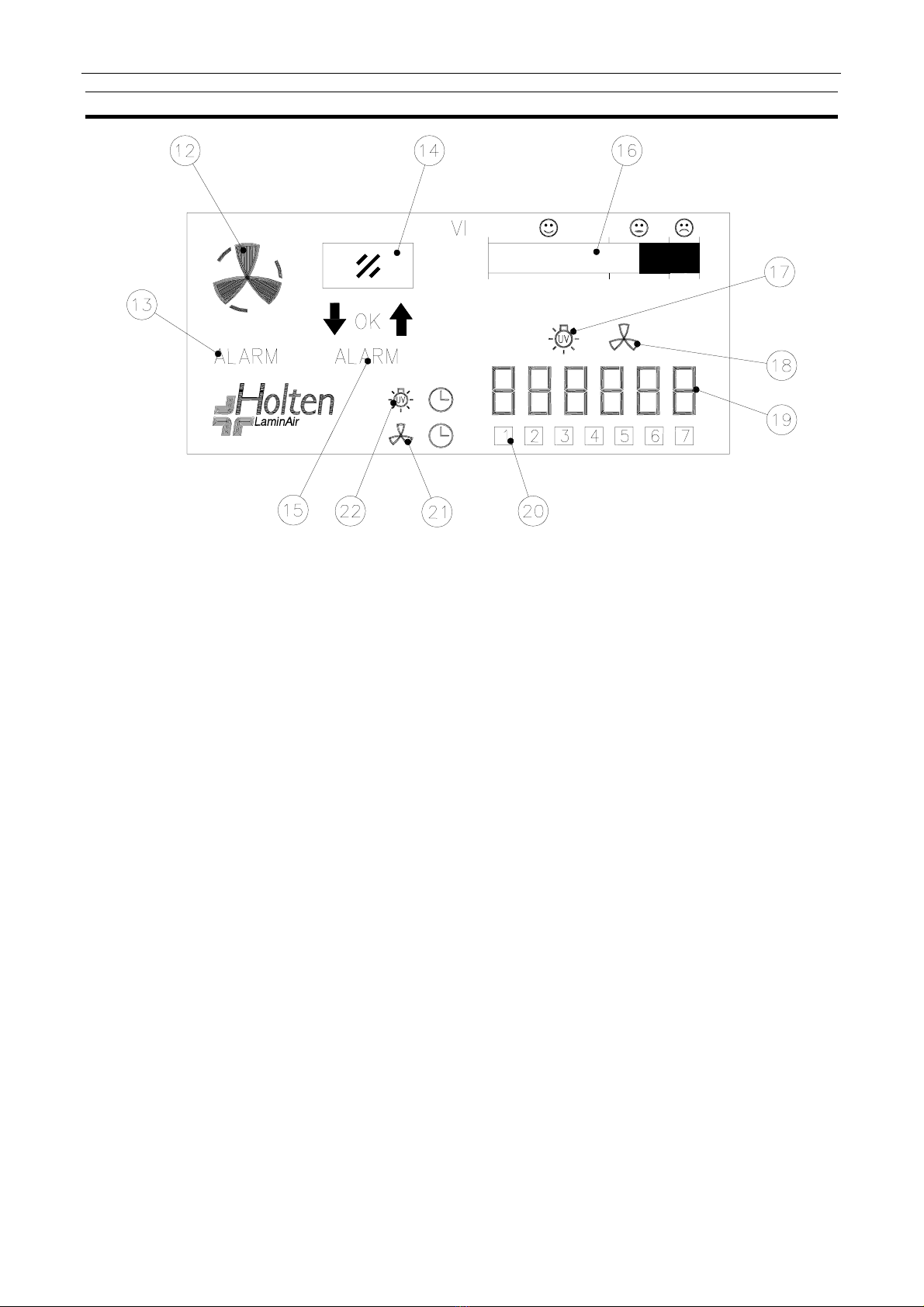
9.2. LCD Display
12. Fan velocity: Normal, Reduced, or Stop.
13. Air velocity not within safe limits. The icon flashes, the acoustic signal sounds and flashing
red light comes on.
14. Front window (sliding sash).
15. Front window not in safe position. The icon flashes, the acoustic signal sounds and flashing
red light comes on.
16. Indication of vertical air velocity in the work chamber (service meter).
17. This icon will illuminate when the UV timer is being programmed.
18. This icon will illuminate when the automatic start-up timer is programmed.
19. Hour counter or clock with fan switch ON or OFF.
20. Indication of weekday.
21. This icon will illuminate when the automatic start-up is programmed and active.
22. This icon will illuminate when the UV timer is activated.
This manual suits for next models
1
Table of contents
Popular Safety Equipment manuals by other brands

Trinity Highway
Trinity Highway SRT 31 System Product Description Assembly Manual

SECUMAR
SECUMAR FREE 100 quick guide

Super Anchor Safety
Super Anchor Safety PD-6101 instruction manual

MSA
MSA BD mini manual

Vertiqual Engineering
Vertiqual Engineering HELI 6 instruction manual

pizzato
pizzato CS MF204 0-P Series manual


