Trinity Highway SRT 31 System User manual

Created November 2021
PN 626825
SRT
TMTM 31 System
Flared End Terminal
Product Description Assembly Manual

TrinityHighway.com 1 Part Number: 626825
©2021 Trinity Highway Products, LLC
Created November 2021
SRT™ 31 System
Flared End Terminal
The Slotted Rail Terminal-31 System (“SRT™ 31 System”) has been tested to National Cooperative Highway
Research Program (“NCHRP”) Report 350 criteria and has been deemed eligible for Federal-aid
reimbursement on the National Highway System (“NHS”) by the Federal Highway Administration (“FHWA”).
Product Description
Assembly Manual
15601 Dallas Parkway
Suite 525
Addison, Texas 75001
Warning: The state/specifying agency, distributors, owners, and contractors
are RESPONSIBLE for the assembly, maintenance, and repair of the SRT™ 31
System. Failure to fulfill these RESPONSIBILITIES with respect to the assembly,
maintenance, and repair of the SRT™ 31 System could result in serious injury or
death.
Important: These instructions are for standard assembly specified by the
state/specifying agency. In the event the specified system assembly, maintenance, or
repair would require a deviation from standard assembly parameters, contact a Trinity
Highway Products, LLC (“Trinity Highway”) representative. This system has been
deemed eligible by the FHWA for use on the NHS under strict criteria utilized by that
state/specifying agency.
This manual must be available to the worker overseeing and/or assembling the product at all
times. For additional copies, contact Trinity Highway at (888) 356-2363 or visit
TrinityHighway.com/Products.
The information contained in this manual supersede all previous versions. The instructions, illustrations,
and specifications are based on the latest SRT™ 31 System information available to Trinity Highway at
publication. We reserve the right to make changes at any time. Please visit TrinityHighway.com/product-
category/end-terminals to confirm the latest revision.
TrinityHighway.com 2 Created November 2021
SRT™ 31 System
Flared End Terminal
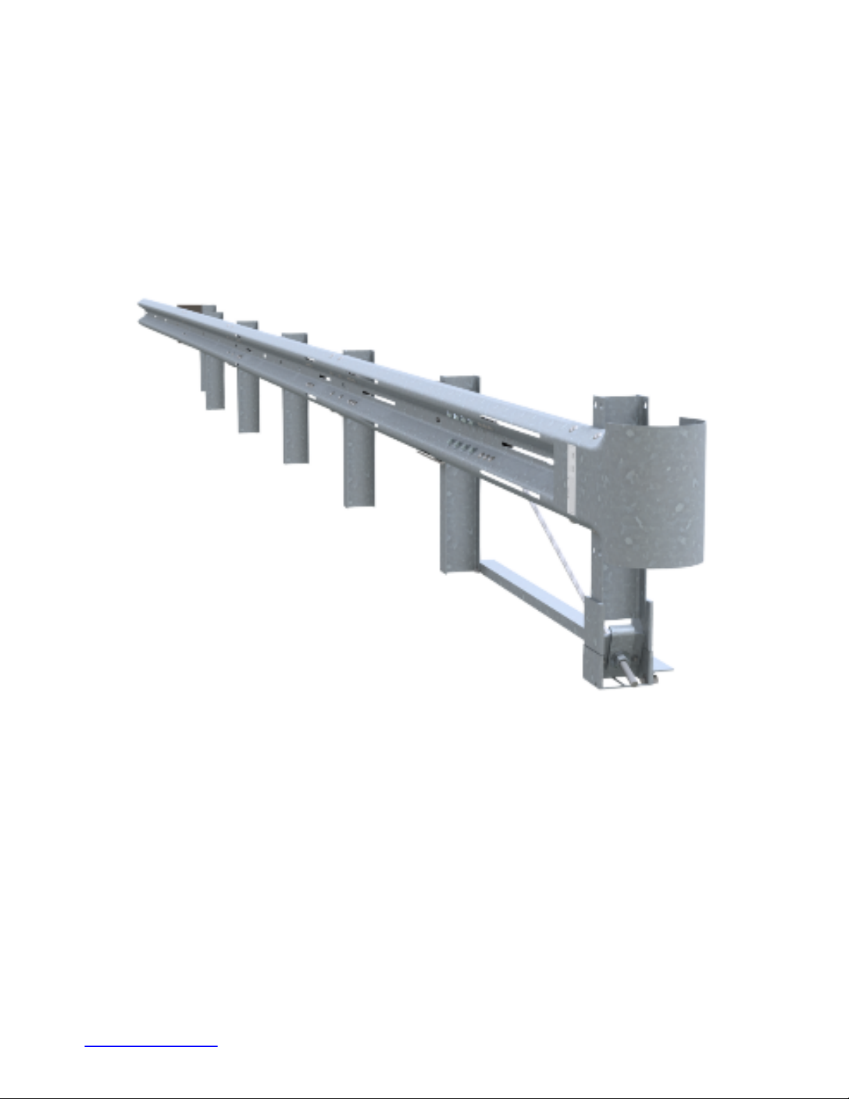
The SRT™ 31 System is a straight flared, single-sided, re-directive, and gating end terminal.

TrinityHighway.com 3 Created November 2021
Table of Contents
Customer Service Contacts ................................................................................................................................. 4
Limitations and Warnings ........................................................................................................................ 5
Overview .................................................................................................................................... 6
Inspect Shipment SRT™ 31 System ....................................................................................................... 8
SRT™ 31 System Components/Hardware ............................................................................................... 9
Recommended Tools ............................................................................................................................. 12
Site Preparation .................................................................................................................................. 13
Post Placement .................................................................................................................................. 14
Rigid Pavement and Rock ..................................................................................................................... 14
Assembly Steps .................................................................................................................................. 14
STEP 1A: SRT™ 31 System (34’-4 1/2” Long) Post Layout .......................................................... 15
STEP 1B: SRT™ 31 System (40’-7 1/2” Long) Post Layout .......................................................... 16
STEP 2A: SRT™ 31 System (34’-4 1/2” Long) Post 2-6 Assembly ................................................ 17
STEP 2B: SRT™ 31 System (40’-7 1/2” Long) Post 2-7 Assembly ................................................ 18
STEP 3: CR Post 1 Bottom Assembly … ...................................................................................... 19
STEP 4: CR Post 1 Top Assembly ............................................................................................... 20
STEP 5: SYTP® 2 Assembly ......................................................................................................... 21
STEP 6: SYTP® 4 Assembly ......................................................................................................... 22
STEP 7A: SRT™ System (34’-4 1/2” Long) SRT™-3 Guardrail Assembly ..................................... 23
STEP 7B: SRT™ System (40’-7 1/2” Long) SRT™-3 Guardrail Assembly ..................................... 24
STEP 8 SRT™ Systems SRT™-2 Guardrail Assembly ............................................................... 25
STEP 9: SRT™ Systems SRT™-1 Anchor Guardrail Assembly ................................................... 26
STEP 10: SRT™ Slot Guard Assembly ........................................................................................... 27
STEP 11: SRT™ Anchor Bracket Assembly ................................................................................... 28
STEP 12: SRT™ Anchor Cable Assembly ..................................................................................... 29
STEP 13: SRT™ Angle Strut Assembly .......................................................................................... 30
STEP 14: SRT™ Buffer Assembly .................................................................................................. 31
STEP 15: SRT™ Delineation Assembly .......................................................................................... 32
SRT™ 31 System Assembly Checklist (File With Project Records) ...................................................... 33
SRT™ 31 System Repair Checklist (File With Maintenance Records) .................................................. 34
SRT™ 31 Routine Inspection Checklist (File with Maintenance Records) ............................................ 35
APPENDIX A: AASHTO Roadside Design Guide Grading Detail ......................................................... 36
APPENDIX B: Leave-Outs .................................................................................................................... 37
APPENDIX C: Encountering Rock ........................................................................................................ 38
NOTES ................................................................................................................................................... 39
SRT™ 31 SYSTEM ACRONYMS
AASHTO American Association of State Highway and Transportation Officials
FHWA Federal Highway Administration
CFR Code of Federal Regulation
CR Cable Release
MUTCD Manual on Uniform Traffic Control Devices
NCHRP National Cooperative Highway Research Program
NHS National Highway System
OSHA Occupational Safety & Health Administration
PPE Personal Protective Equipment
SYTP® Steel Yielding Terminal Post®
SRT™ 31 System Slotted Rail Terminal-31 System
TL-X Test Level X; X refers to the different Test Levels; 1, 2 or 3
Trinity Highway Trinity Highway Products, LLC

TrinityHighway.com 4 Created November 2021
Customer Service Contacts
Trinity Highway is committed to the highest level of customer service. Feedback regarding the
SRT™ 31 System, its assembly procedures, supporting documentation, and performance is
always welcome. Additional information can be obtained from the contact information below:
Trinity Highway
Telephone
(888) 356-2363 (USA)
+1 214 589 8140 (International)
Contact Link
TrinityHighway.com\Contact
Website:
www.trinityhighway.com
Trinity Highway Products, LLC
15601 Dallas Parkway
Suite 525
Addison, TX 75001

TrinityHighway.com 5 Created November 2021
Limitations and Warnings
Trinity Highway, in compliance with NCHRP-350,
contracts with ISO 17025 A2LA accredited testing
laboratories to perform crash tests, evaluate tests, and
submit the test results to the FHWA for review.
The SRT™ 31 System has been deemed eligible by
FHWA as meeting the requirements and guidelines of
NCHRP Report 350, Test Level 3 (“TL-3”). These tests
typically evaluate product performance defined by
NCHRP Report 350 involving a range of vehicles on
roadways, from lightweight cars (approx. 800 kg [1800
lb.]) and full size pickup trucks (approx. 2,000 kg [4,400
lb.]) at 100 kph [62 mph].
The SRTTM 31 System is tested pursuant to the test
matrix criteria of NCHRP Report 350 as designated
by FHWA. The FHWA tests are not intended to
represent the performance of systems when
impacted by every vehicle type or in every impact
condition existing on the roadway. Every departure
from the roadway is a unique event.
Trinity Highway expressly disclaims any warranty or
liability for injury or damage to persons or property
resulting from any impact, collision or harmful contact
with its products, other vehicles, or nearby hazards or
objects by any vehicle, object or person, whether or not
the products were assembled in consultation with
Trinity Highway or by third parties.
The SRT™ 31 System is intended to be assembled,
delineated, and maintained within state/specifying
agency and federal guidelines. It is important for the
state/specifying agency specifying the use of a highway
product to select the most appropriate product
configuration for site specifications.
The state/specifying agency’s careful evaluation of
the site layout, vehicle population type and speed,
traffic direction, and visibility are some of the
elements that require evaluation in the selection of
a highway product. For example, curbs could cause
an untested effect on an impacting vehicle.
After an impact with the system, all debris must be
removed from the area immediately in compliance with
the most applicable state/specifying agency policy. The
specified SRT™ 31 System must be evaluated and
restored to its original specified condition or replaced
as the state/specifying agency determines/requires, as
soon as possible. Product selection, approval, proper
installation, and maintenance of any highway product is
the sole responsibility of the state/specifying agency
and the state DOT.
Safety Alert Symbols appear throughout this
manual and indicate Danger, Warning, Caution or
Important statements. Failure to read and follow
these warnings could result in serious injury or
death in the event of a vehicle impact with the
system.
WARNING: Do not assemble, maintain, or repair
the SRT™ 31 System until you have read this manual
thoroughly and completely understand it. Ensure that
all Danger, Warning, Caution, and
Important
statements within the manual are completely
followed. Please call Trinity Highway at (888)
356-2363 if you have any questions about
instructions in this manual.
WARNING: Safety measures incorporating
appropriate traffic control devices and personal
protective equipment ("PPE") specified by the
state/specifying agency must be used to protect all
personnel while at the assembly, maintenance, or
repair site.
WARNING: Ensure the assembly site meets all
appropriate Manual on Uniform Traffic Control
Devices (“MUTCD”) and state/specifying agency
standards.
WARNING: Only Trinity Highway parts that are
specified herein can be used for assembly,
maintenance, or repair on them SRT™ 31 System.
Do not utilize or otherwise commingle parts from
other systems, even if those systems are other
Trinity Highway systems. Such configurations have
not been tested, nor have they been approved for
use.
Assembly,
maintenance or repairs using
unspecified parts or accessories is strictly
prohibited. Failure to follow this warning could result
in serious injury or death in the event of a vehicle
impact with such an UNACCEPTED system.
WARNING: Do NOT modify the SRT™ 31 System in
any way.
IMPORTANT: Trinity Highway makes no
recommendation whether use or reuse of any part
of the SRT™ 31 System is appropriate or acceptable
after system impact. It is the responsibility of the
state/specifying agency and its engineers to make
that determination.
IMPORTANT: It is the responsibility of the applicable
owner, state/specifying agency, or specifier to
inspect the SRT™ 31 System after assembly is
complete to ensure the instructions provided in this
manual have been strictly followed.

TrinityHighway.com 6 Created November 2021
Overview
The SRT™ 31 System is a straight flared, single-sided, re-directive, and gating end terminal. The SRT™
31 System is a 31” [787 mm] high (measured from top of rail to finished grade) end terminal used to
shield 31” [787 mm] high strong post W-beam guardrail.
The SRT™ 31 System consists of one (1) SRTTM Anchor Guardrail, and two (2) SRT Guardrails, Cable
Release (CR) Post at post location 1, Steel Yielding Terminal Post® (“SYTP®”) at post locations 2-6,
SRT™ Angle Strut, SRT™ Cable Anchor Bracket and SRT™ Anchor Cable, SRT™ Shelf Angle at post
2, SRT™ Flange Protector at posts 2, 4, & 6, SRTTM Slot Guards downstream of slots, SRT™ Buffer,
and various other required hardware accessories.
The CR Post 1 Bottom is fabricated from a W6x15# Structural Beam approximately 6’-3 1/2” [1.91 m] in
length from top of the side plates to bottom of the embedded portion. Combined with the CR Post 1 Top,
they become the SRTTM Anchor Post shown below.
SRT™ System (34’-4 1/2” Long - 31” High)
Reference drawing: SS436

TrinityHighway.com 7 Created November 2021
SRT™ 31 System (40’-7 1/2” Long - 31” High)
Reference drawing: SS616

TrinityHighway.com 8 Created November 2021
Inspect Shipment
Carefully unpack and inspect all components for damage. Check the received parts against the packing
list supplied with the system. If any parts are damaged, missing, or unspecified; do not attempt to
assemble the system and contact Trinity Highway immediately (p. 4).
Warning: Use only Trinity Highway parts that are specified by Trinity Highway
for use with the SRT™ 31 System for assembling, maintaining, or repairing the
SRT™ 31 System. Do not utilize or otherwise commingle parts from other
systems even if those systems are other Trinity Highway Systems.
ID
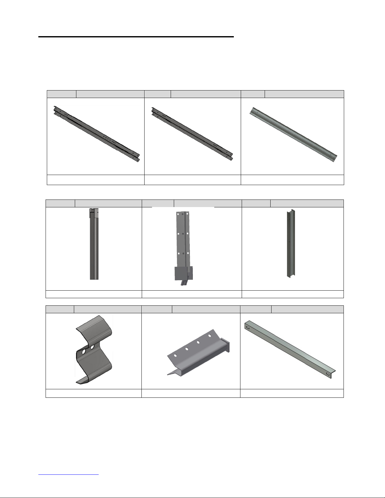
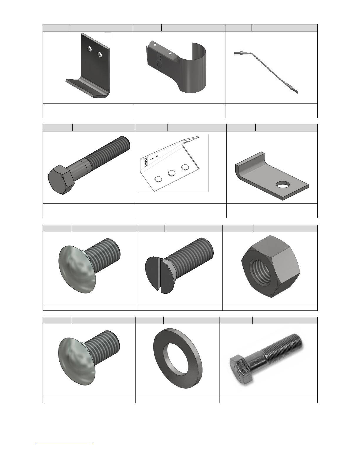
SRT™ 31 SYSTEM COMPONENTS/HARDWARE
PN
SS 436
34’-4½”
SS 616
40’-7½”
A
SRT™-1 Anchor Guardrail 12’-6” [3.810 m]
30G
1
1
B
SRT™-2 Guardrail 12’-6” [3.810 m]
39G
1
1
C
SRT™-3 Guardrail 9’-4 1/2” [2.857 m]
10967G
1
0
D
CR Post 1 Bottom W6 x 15# [W6 x 22.5 kg]
34052A
1
1
E
CR Post 1 Top W6 x 8.5# [W150 x 13 kg]
34053A
1
1
F
SYTP® 6’-0” [1.83 m]
15000G
5
5
G
SRT™ Flange Protector at Posts 2,4,6
7G
3
3
I
SRT™ Cable Anchor Bracket
700A
1
1
K
SRT™ Angle Strut 3” x 3” x 1/4” [75 mm x 75 mm x 6 mm]
33875G
1
1
L
SRT™ Shelf Angle (At Post 2)
34054G
1
1
M
SRT™ Buffer
907G
1
1
N
SRT™ Cable Assembly 3/4” x 6’-6”
3000G
1
1
O
5/16” x 1.75” Hex Bolt (At Post 1)
4211G
2
2
P
SRT™ Slot Guard - NOTE Orientation of Arrows
9960G
4
4
Q
SRT™ Cable Anchor Bracket Angle (At Post 1)
33909G
1
1
R
5/8” x 2” HGR Post Bolt (At Posts 1, 2, & 4)
3400G
4
4
S
5/8” x 1.75” Countersunk HD Bolt (At Post 6)
4419G
1
1
T
1” Hex Nut (At Cable Ends)
3910G
2
2
U
5/8” x 1.25” GR Bolt
3360G
52
52
V
1” Round Washer (At Cable Ends)
3900G
2
2
W
5/8” x 1.5” Hex Bolt
3380G
8
8
X
5/8” x 1.75” Hex Bolt (A325) (At Strut)
3391G
2
2
Y
5/16” Round Washer (At Post 1)
3240G
2
2
Z
SRT™-3 Guardrail 15’-7 1/2” [4.762 m]
20442G
0
1
AA
5/8” Round Washer
3300G
12
12
BB
5/8” GR Hex Nut
3340G
67
67
CC
5/16” Hex Nut (At Post 1)
3245G
2
2
DD
EE
DELINEATION OPTIONS: Reflective Sheeting
16” x 16” [400 mm x 400 mm] Striped Yellow/Black
16” x 16” [400 mm x 400 mm] Solid Yellow
Both 6665B and 6666B can be used for Left or Right
applications or use the state standards.
6665B
6666B
1
1
1
1
TrinityHighway.com 9 Created November 2021
SRT™ 31 System Components/Hardware
Below is a pictorial depiction of the components/hardware for SRT™ 31 System Please see the Trinity Highway
drawings and page 8 of this manual for specific lists of components/hardware and quantities required for SRT™
31 System selected to be assembled.
Note: The following components/hardware are not shown to scale.
ID: A
PN: 30G
ID: B
PN: 39G
ID: C
PN: 10967G
SRT™-1 Anchor Guardrail 12’-6”
SRT™-2 Guardrail 12’-6”
SRT™-3 Guardrail 9’-4 1/2”
ID: D
PN: 34052A
ID: E
PN: 34053A
ID: F
PN: 15000G
CR Post 1 Bottom
CR Post 1 Top
SYTP® 6’-0”
ID: G
PN: 7G
ID: I
PN: 700A
ID: K
PN: 33875G
SRT™ Flange Protector
SRT™ Cable Anchor Bracket
SRT™ Angle Strut
TrinityHighway.com 10 Created November 2021
ID: L
PN: 34054G
ID: M
PN: 907G
ID: N
PN: 3000G
SRT™ Shelf Angle
SRT™ Buffer
SRT™ Cable Assembly
3/4” x 6’-6”
ID: O
PN: 4211G
ID: P
PN: 9960G
ID: Q
PN: 33909G
5/16” x 1.75” Hex Bolt
SRT™ Slot Guard
SRT™ Cable Anchor Bracket
Angle
ID: R
PN: 3400G
ID: S
PN: 4419G
ID: T
PN: 3910G
5/8” x 2” HGR Post Bolt
5/8” x 1.75” C.S. HD Bolt
1” Hex Nut
ID: U
PN: 3360G
ID: V
PN: 3900G
ID: W
PN: 3380G
5/8” x 1.25” GR Bolt
1” Round Washer
5/8” x 1.5” Hex Bolt

TrinityHighway.com 11 Created November 2021
ID: X
PN: 3391G
ID: Y
PN: 3240G
ID: Z
PN: 20442G
5/8” x 1.75” Hex Bolt (A325)
5/16” Round Washer
SRT™-3 Guardrail 15’ 7 1/2””
ID: AA
PN: 3300G
ID: BB
PN: 3340G
ID: CC
PN: 3245G
5/8” Round Washer
5/8” GR Hex Nut
5/16” Hex Nut
ID: DD
PN: 6665B
ID: EE
PN: 6666B
Delineation Striped
Yellow/Black
Delineation Solid
Yellow
Both 6665B and 6666B can be used for Left or Right applications

TrinityHighway.com 12 Created November 2021
Recommended Tools
Documentation
•
Manufacturer’s SRT™ 31 Product Description Assembly Manual (Current Version)
•
SRT™ 31 System Drawing(s). Current Version of SS 436 or SS 616
Personal Protective Equipment
•
Eye Protection
•
Work Gloves
•
Safety-Toe Shoes
•
Back Protection
•
Hard Hat
•
Reflective Vest
•
Apron
Miscellaneous
•
Traffic Control Equipment and Plan per local standards and the MUTCD
•
SAE Combination Wrench Set
•
Socket Set & Socket Wrench
•
Hammer
•
Chalk Line
•
Tape Measure
•
Marking Paint and Pen
•
Straight Edge
•
Level
•
Plumb Line
•
Post Pounder (commonly used for driving posts)
•
Auger
•
Soil Tamper
•
5/8” Alignment Tool (Drift Pin)
•
Locking Pliers
Note: The provided list of tools is a general recommendation and should not be considered an
extensive list. Depending on specific site conditions and the complexity of the assembly specified
by the state/specifying agency, the required tools may vary. Decisions as to what tools are needed
to perform the job are entirely the responsibility of the state/specifying agency and the selected
contractor performing the assembly of the system at the state/specifying agency’s site.
TrinityHighway.com 13 Created November 2021
Site Preparation
The SRT™ 31 System is a straight flared, single-sided, re-directive, and gating end terminal. It may be
specified for use by the state/specifying agency in conjunction with strong post W-beam guardrail systems
on the roadside or median of a roadway. The decision to specify the SRT™ 31 System for a particular
project is the responsibility of the state/specifying agency design engineer who must ensure that the most
appropriate end terminal has been selected for the specific site conditions.
The SRT™ 31 System is designed to be attached to strong post W-beam guardrail systems that have been
accepted under NCHRP Report 350 crash test criteria that use either no offset blocks, 8” [203 mm] offset blocks
or 12” [305 mm] offset blocks.
Important: The SRT™ 31 System must not be attached directly to a weak post W-beam
guardrail system without an approved weak-post-to-strong-post transition plus a
minimum of 12’-6” [3.81 m] strong post W-beam guardrail with 6’-3” [1.91 m] post
spacing. The 12’-6” [3.81 m] strong post W-beam guardrail must be placed between the
SRT™ 31 System and the weak-post- to-strong-post transition.
Important: The SRT™ 31 System must not be attached directly to Thrie Beam, Thrie
Beam Transition, or to a post which is stronger/stiffer than a standard W-beam W6x8.5#
[W150x13] or W6x9# [W150x13.5] guardrail post. A minimum of 6’-3” [1.91 m] strong
post single ply W-beam guardrail must be placed between the SRT™ 31 System and the
Thrie Beam transition (or stronger/stiffer post).
Important: Do not attach the SRT™ 31 System directly to a rigid barrier (i.e. concrete
barrier, wall or bridge pier) without the use of a state/specifying agency approved
transition.
Important: Ensure that the SRT™ 31 System application conforms to the AASHTO
Roadside Design Guide.
Important: Trinity Highway does not direct grading. Proper site grading must be
accomplished before assembly of the SRT-31 System in accordance with local
guidelines OR the AASHTO Roadside Design Guide (see Appendix A), whichever is
more stringent. Failure to follow this warning could result in serious injury or death in
the event of a vehicle impact with the system.
Important: The Beginning Length of Need (“BLON”) for the SRT™ 31 System was
established during NCHRP Report 350 Test 3-35 at Post #3, which is 12’-6” [3.81 m] from
the center of Post #1.
Important: A minimum of 75’ [22.86 m] of strong post W-beam guardrail with 6’-3”
[1.90 5m] post spacing must be placed between two SRT™ 31 Systems when installed
with both an approach and departing end on NCHRP Report 350 TL-3 roadway
applications. For roadway applications that meet the NCHRP Report 350 Test Level 2
(TL-2) or Test Level 1 (TL-1) criteria, the SRT™31 TL-3System can be placed “end to
end”, if specified and approved by the state/specifying agency. The minimum installation
length for TL-2 and TL-1 applications is 81'-3" [24.77 m] long consisting of two (2) 40’-7
1/2” Systems or two (2) 34’-4 1/2” Systems plus one (1) 31” high, 12’-6” strong post single
ply 12 gauge W-beam guardrail system.

TrinityHighway.com 14 Created November 2021
SRT™ 31 System Post Placement
The SRT™ 31 System posts may be inserted into the soil using an auger or post pounding equipment
for placement of guardrail posts. If an auger is used, ensure diameter is large enough to allow for proper
compaction of state/specifying agency approved fill material. All SRT™ 31 System posts must be
assembled within established standard construction tolerances, including being plumb. Compaction for
all posts must be within state/specifying agency guidelines.
Danger: It is the responsibility of the installer to ensure all above & below ground utilities
as well as drainage structures are located, marked, and identified prior to using an auger
or post pounding tool in accordance with state/specifying agency guidelines. Failure to
follow this warning could result in serious injury or death.
Rigid Pavement and Rock
If rigid pavement (e.g. concrete or asphalt) of any thickness is encountered within the system pay length,
ensure a proper “leave-out” area (the specified size of open space as defined in the AASHTO Roadside
Design Guide) is provided around the posts and filled with state/specifying agency approved backfill
material. See Appendix B for “leave-out” requirements of the SYTP®.
If rock is encountered within the system pay length, follow the criteria as defined in the AASHTO Roadside
Design Guide. See Appendix C for requirements for the assembly of the CR Post 1 Bottom or SYTP®.
Drilling Holes into Rock
Caution: It is the responsibility of the installer to consult Occupational Safety & Health
Administration (“OSHA”) silica respiratory standard 29 Code of Federal Regulation (“CFR”)
1910.134 for debris removal and ensure compliance.
Assembly Steps
NOTE: The order in which the steps appear in this manual are not necessarily the order
in which they must be followed. ALL STEPS MUST BE COMPLETED.
Important: Trinity Highway does not direct grading. Proper site grading must be
accomplished before assembly of the SRT™ 31 System in accordance with
state/specifying agency guidelines OR the AASHTO Roadside Design Guide (see
Appendix A), whichever is more stringent. Failure to follow this warning could result in
serious injury or death in the event of a vehicle impact with the system.
Note: Below ground portions in the assembly steps are not shown for clarity.
TrinityHighway.com 15 Created November 2021
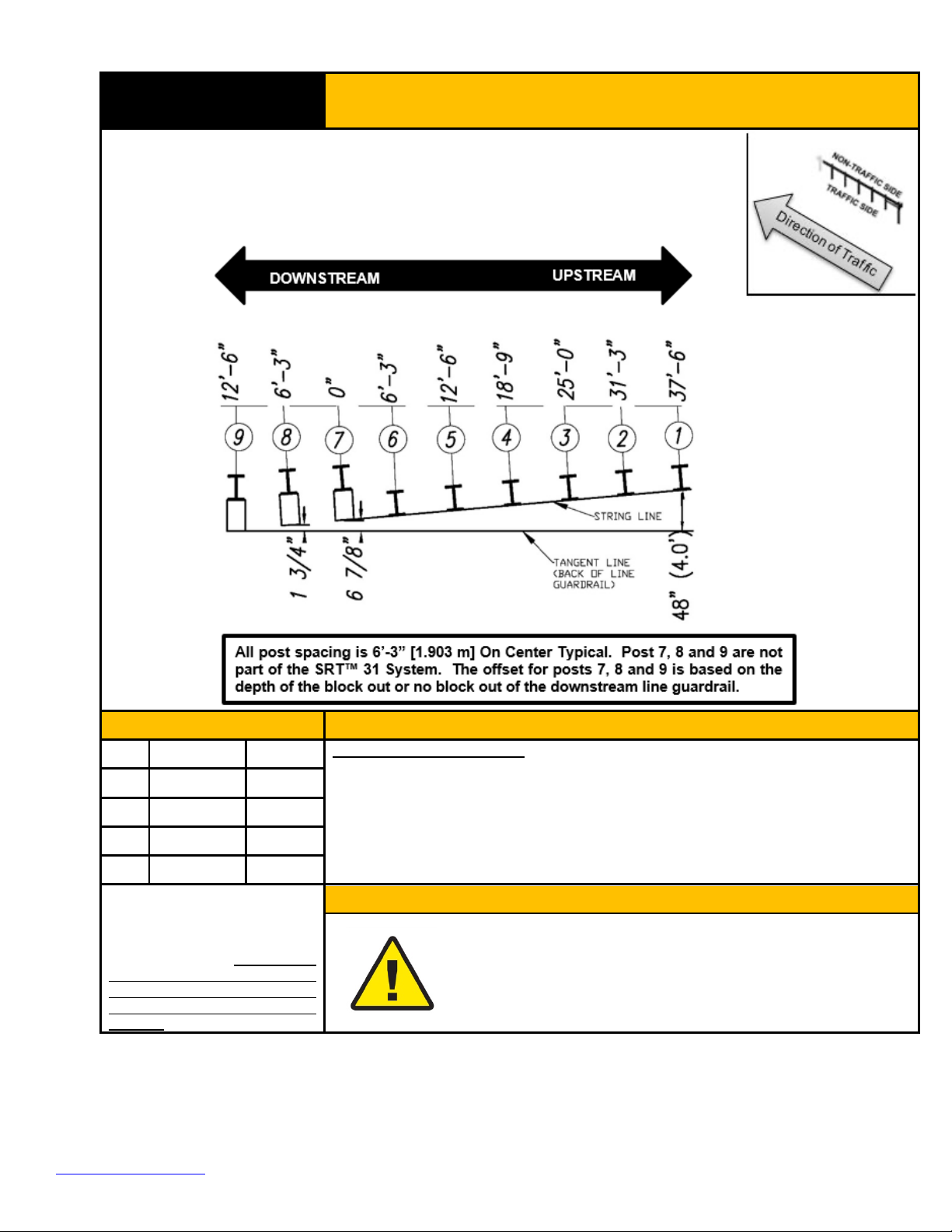
STEP 1A
SRT™ 31 System (34’-4 1/2”Long) Post Layout
PARTS
INSTRUCTIONS
Reference Drawing SS436
1. Layout the post as shown above.
2. Posts 6-2 are to be aligned with the string line between the block face of Post
7 or the face of Post 7 (for no block systems) and the face of Post 1.
3. Layout and placement of the posts are critical to the assembly of the
SRT™ 31.
Use only Trinity Highway parts
that are specified herein for the
SRT™ 31 System for assembling,
maintaining, or repairing the
SRT™ 31 System. Do not utilize
or otherwise commingle parts
from other systems even if those
systems are Trinity Highway
systems.
WARNINGS
Ensure proper site grading in accordance with state/specifying
agency guidelines or the AASHTO Roadside Design Guide,
whichever is more stringent. Failure to follow this warning could
result in serious injury or death in the event of a vehicle impact with
the system.
TrinityHighway.com 16 Created November 2021
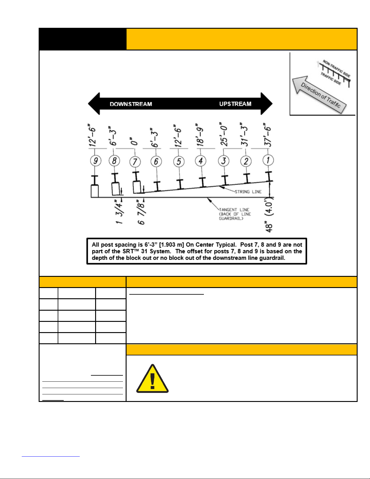
STEP 1B
SRT™ 31 System (40’-7 1/2” Long) Post Layout
PARTS
INSTRUCTIONS
Reference Drawing SS616
1. Layout the post as shown above.
2. Posts 6-2 are to be aligned with the string line between the block face of Post
7 or the face of Post 7 (for no block systems) and the face of Post 1.
3. Layout and placement of the posts are critical to the assembly of the
SRT™ 31.
Use only Trinity Highway parts
that are specified herein for the
SRT™ 31 System for assembling,
maintaining, or repairing the
SRT™ 31 System. Do not utilize
or otherwise commingle parts
from other systems even if those
systems are Trinity Highway
systems.
WARNINGS
Ensure proper site grading in accordance with state/specifying
agency guidelines or the AASHTO Roadside Design Guide,
whichever is more stringent. Failure to follow this warning could
result in serious injury or death in the event of a vehicle impact with
the system.
TrinityHighway.com 17 Created November 2021
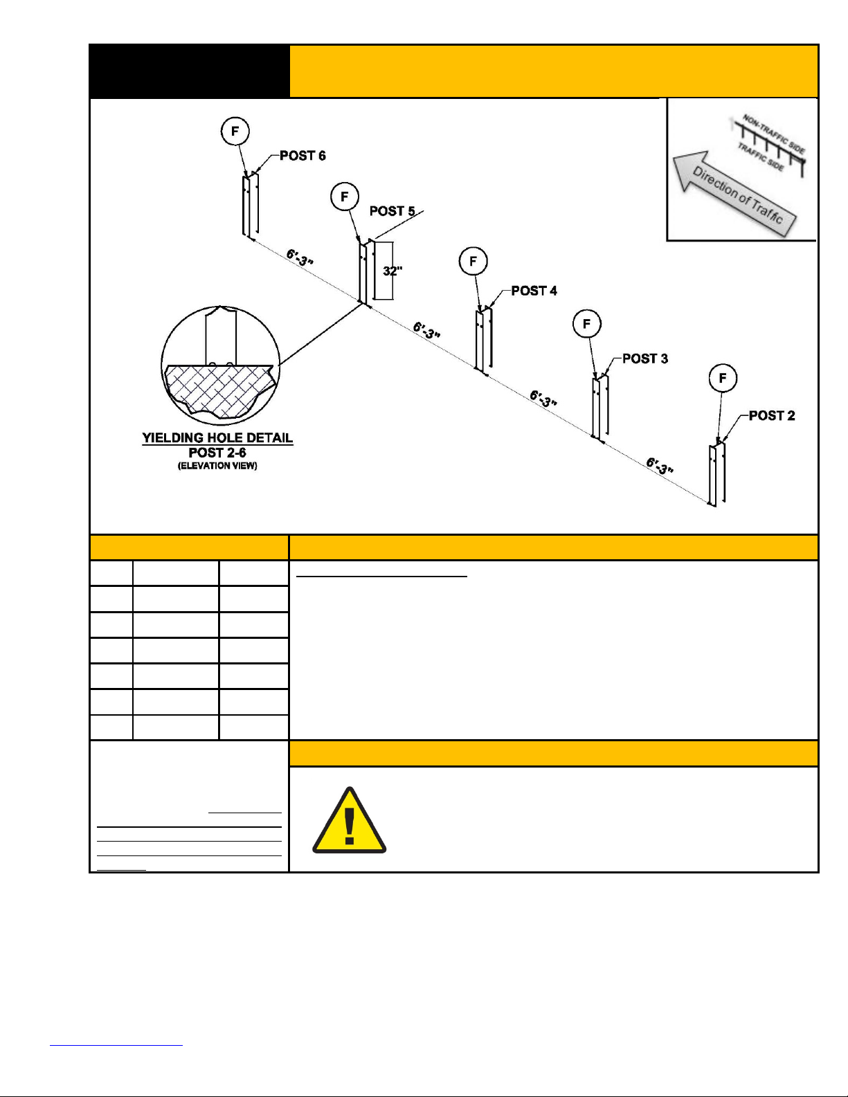
STEP 2A
SRT™ 31 System (34’-4 1/2” Long)
Post 2-6 Assembly
PARTS
INSTRUCTIONS
F
15000G
5 EA
Reference Drawing SS436
1. Assemble all parts in the configuration and orientation as shown above.
2. The SRT™ 31 System must be attached to a 31” [787 mm] high strong post
W-beam guardrail system or to a strong post W-beam guardrail that has
been properly transitioned to 31” [787 mm] rail height per state/specifying
state/specifying agency.
3. Ensure proper post spacing and post height are achieved for 6’ SYTP® 2-6
(Part F) per shown dimensions above.
4. Ensure the center of the SYTP® yielding holes are approximately at finished
grade as shown.
Use only Trinity Highway parts
that are specified herein for the
SRT™ 31 System for assembling,
maintaining, or repairing the
SRT™ 31 System. Do not utilize
or otherwise commingle parts
from other systems even if those
systems are Trinity Highway
systems.
WARNINGS
Ensure proper site grading in accordance with state/specifying
agency guidelines or the AASHTO Roadside Design Guide,
whichever is more stringent. Failure to follow this warning could
result in serious injury or death in the event of a vehicle impact with
the system.
TrinityHighway.com 18 Created November 2021
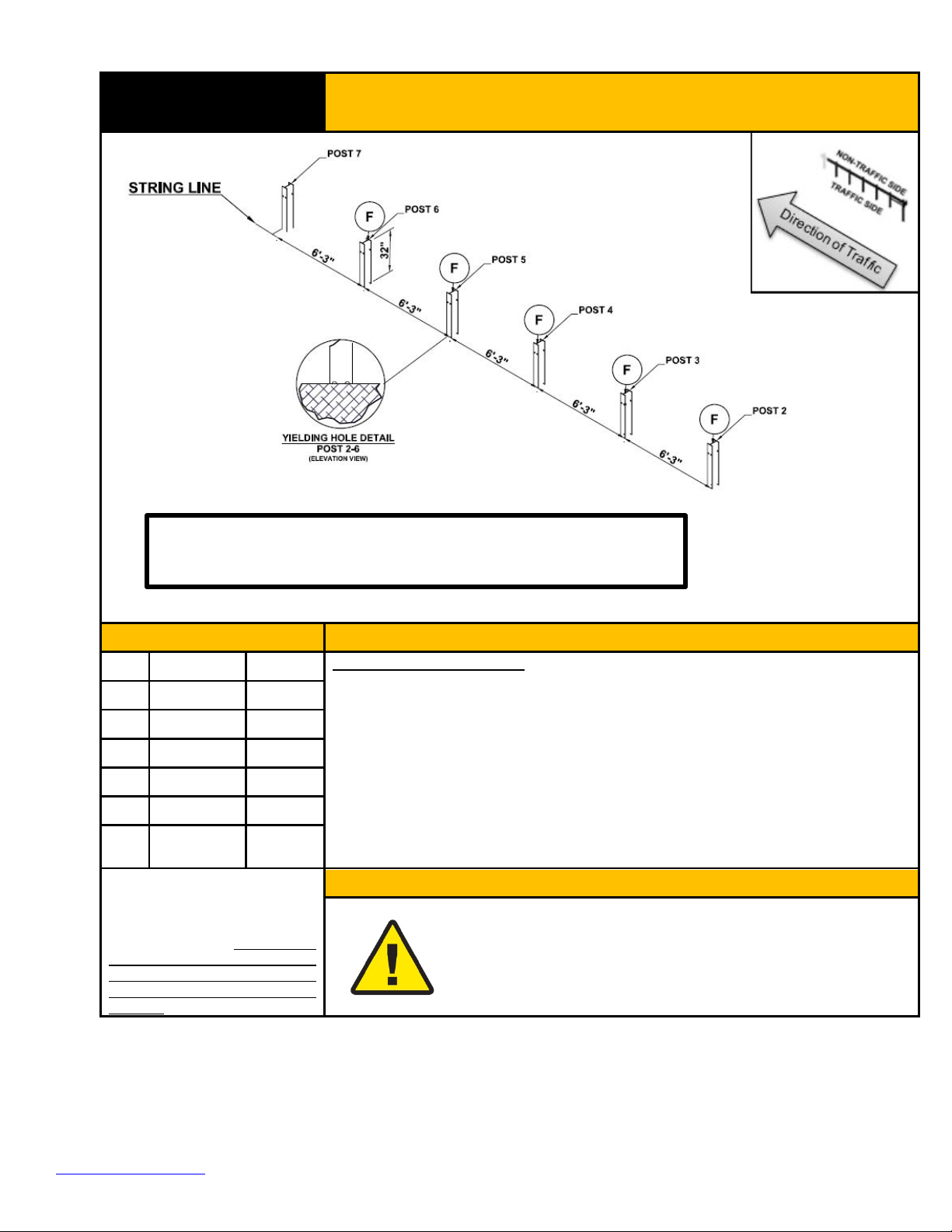
STEP 2B
SRT™ 31 System (40’- 7 1/2” Long)
Post 2-7 Assembly
PARTS
INSTRUCTIONS
F
15000G
5 EA
Reference Drawing SS616
1. Assemble all parts in the configuration and orientation as shown above.
2. The SRT™ 31 System must be attached to a 31” [787 mm] high strong post
W- beam guardrail system or to a strong post W-beam guardrail that has
been properly transitioned to 31” [787 mm] rail height per state/specifying
state/specifying agency.
3. Ensure proper post spacing and post height are achieved for 6’ SYTP® 2-6
(Part F) and post 7 per shown dimensions above.
4. Ensure the center of the SYTP® yielding holes are approximately at
finished grade as shown.
5. Post 7 is a standard 6’ [1.83 m] long W6x8.5# [W150x13 kg] or W6x9#
[W150x13.5 kg] guardrail post.
Use only Trinity Highway parts
that are specified herein for the
SRT™ 31 System for assembling,
maintaining, or repairing the
SRT™ 31 System. Do not utilize
or otherwise commingle parts
from other systems even if those
systems are Trinity Highway
systems.
WARNINGS
Ensure proper site grading in accordance with state/specifying
agency guidelines or the AASHTO Roadside Design Guide,
whichever is more stringent. Failure to follow this warning could
result in serious injury or death in the event of a vehicle impact with
the system.
The offset for posts 7 is based on the depth of the blockout or no
blockout of the downstream line guardrail. Post 7 is not part of the
SRT™ 31 System Bill of Materials. Post 7 is part of the line
guardrail quantities.
TrinityHighway.com 19 Created November 2021
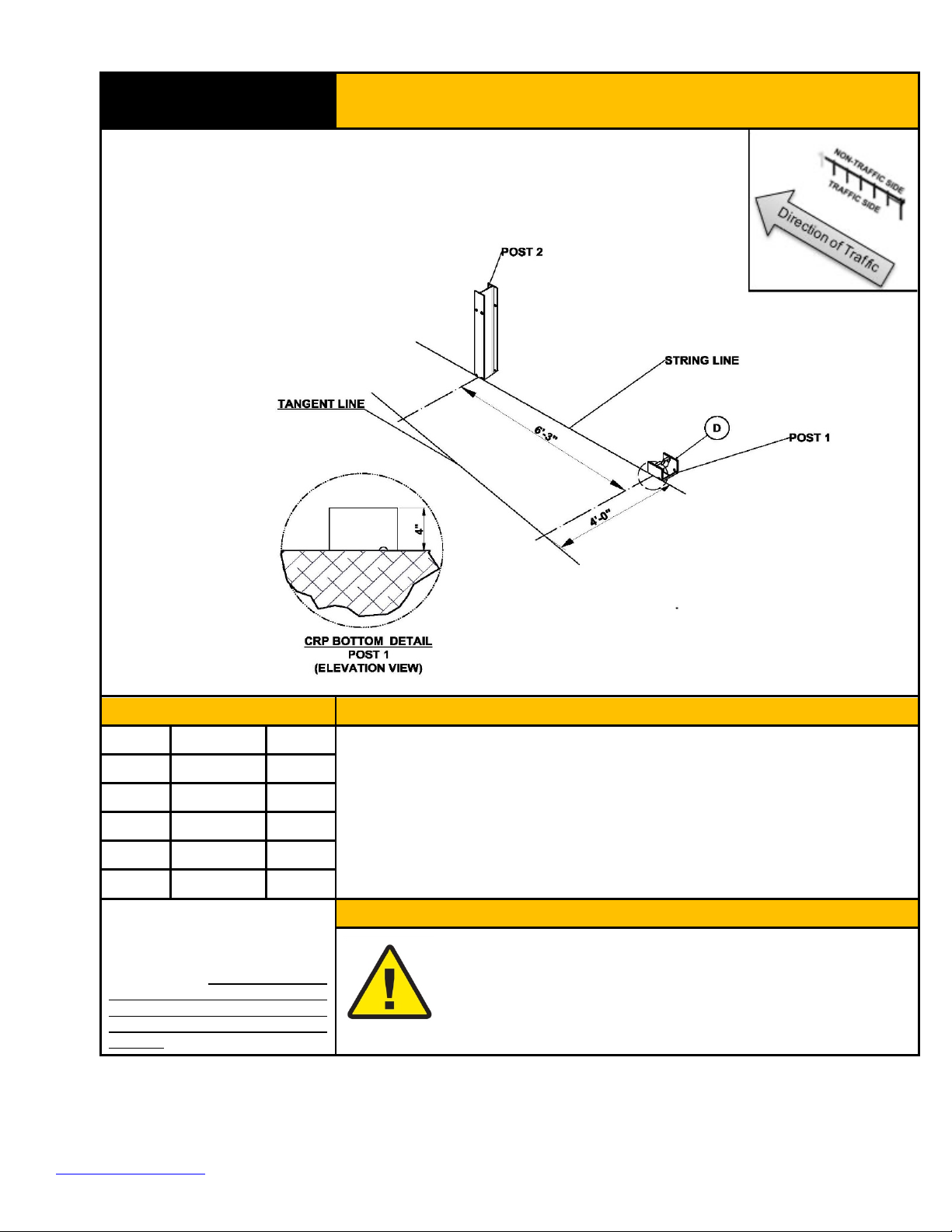
STEP 3
CR Post 1 Bottom Assembly
PARTS
INSTRUCTIONS
D
34052A
1 EA
1. Assemble the CR Post 1 Bottom (Part D) in the configuration and
orientation as shown above.
2. Ensure the CR Post 1 Bottom is installed approximately plumb and
oriented with the hole being closest to the upstream end of the CR Post 1
Bottom.
3. Ensure the top of the CR Post 1 Bottom does not exceed 4” [100 mm] above
finished grade.
Use only Trinity Highway parts that
are specified herein for the SRT™
31 System for assembling,
maintaining, or repairing the SRT™
31 System. Do not utilize or
otherwise commingle parts from
other systems even if those
systems are Trinity Highway
systems.
WARNINGS
Ensure proper site grading in accordance with state/specifying
agency guidelines or the AASHTO Roadside Design Guide,
whichever is more stringent. Ensure the CR Post 1 Bottom is
oriented correctly and the height does not exceed 4” [100 mm]
above finished grade. Failure to follow this warning could result in
serious injury or death in the event of a vehicle impact with the
system
Table of contents
Other Trinity Highway Safety Equipment manuals


Popular Safety Equipment manuals by other brands

Lanex
Lanex PB-20 instruction manual

SKYLOTEC
SKYLOTEC ANCHOR ROPES Instructions for use

Besto
Besto Buoyancy Aid 50N Instructions for use

TEUFELBERGER
TEUFELBERGER NODUS Manufacturer's information and instructions for use

Troy Lee Designs
Troy Lee Designs Tbone Product owners manual

Innova
Innova Xtirpa Instruction and safety manual

bolle SAFETY
bolle SAFETY B810 quick start guide

SHENZHEN FANHAI SANJIANG ELECTRONICS
SHENZHEN FANHAI SANJIANG ELECTRONICS A9060T instruction manual

Hiltron security
Hiltron security POWER8E Installation and use manual

Salewa
Salewa MTN SPIKE user manual

Hatco
Hatco B-950P installation guide

Sitec
Sitec TX MATIC operating manual


